Options
Defines the LOD (level of detail), i.e., how detailed certain objects will be displayed in the Viewports. These settings set the otherwise steplessly adjustable Level of Detail setting in the Project Settings.
25%
50%
The setting affects the level of detail (LOD) shown for objects that support LOD. The lower the setting, the faster the display.
Here you can define for each view if the LOD defined in the respective settings (e.g., Subdivision Surfaces or Metaballs) should be used for rendering.
Enable this option if you want a stereoscopic display in the Viewport. Details regarding stereoscopy can be found here. Note that a stereoscopic depiction is only possible in the Parallel or Perspective views.
Here the display of colors, shaders, etc. in the Viewport can be turned off, in consideration of linear workflow.
Use this setting to define whether or not a given display should be done in Enhanced OpenGL quality.
The more complex the scene the slower the refresh rate will be.
Note that you can also define at material level which channels should be displayed (Editor channel).
Use this setting to define whether or not Enhanced OpenGL should display transparency in high quality. Note that antialiasing does not work in the Viewport in this mode.
Use this setting to define whether or not Enhanced OpenGL should display shadows.
Use this setting to define whether or not Enhanced OpenGL should display post effects. Note that Enhanced OpenGL offers only limited support for Cinema 4D post effects.
 Left: OpenGL display. Right: Rendered image.
This is where you can enable the display of the Noise Shader for Enhanced OpenGL.
Defines for Enhanced OpenGL whether or not reflections should be displayed. Details can be found here
Defines whether or not an Ambient Occlusion approximation should be rendered in the Viewport in conjunction with Enhanced OpenGL. See also SSAO.
Defines wheter or not tessellation should be displayed for respective objects in the Viewport in conjunction with Enhanced OpenGL. See also Tessellation.
Defines for Enhanced OpenGL if a simulated depth of field should be displayed. For details see Depth of Field.
Use this option to toggle backface culling on or off when in Lines mode. Backface culling can speed up the display and make the scene easier to understand and edit. With backface culling, all concealed surfaces are hidden. A backface is a surface that points away from the camera.
Cinema 4D knows the direction of a surface by looking at its surface normal. If the surface normal points towards the camera, the surface is a front face. If the surface normal points away from the camera, the surface is a backface and is not drawn when Backface Culling is enabled. Figure 1 demonstrates the backface principle.
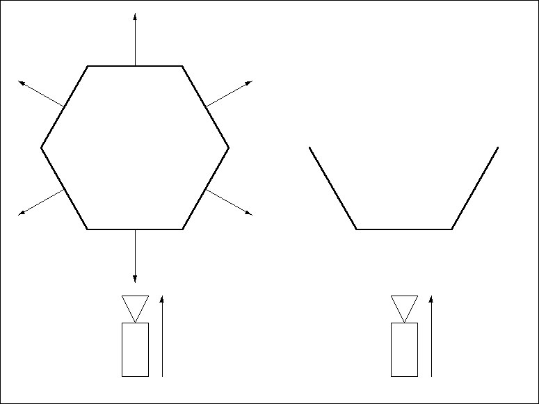 Figure 1.
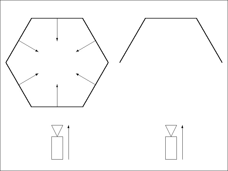 Figure 2.
By convention, the Normals should point outwards from their surfaces, as in Figure 1. Objects with Normals that point inwards may cause display errors. To remedy, reverse the Normals, as illustrated in Figure 2, using the Reverse Normals command (Functions menu).
The following picture demonstrates how backface culling applied to a sphere.
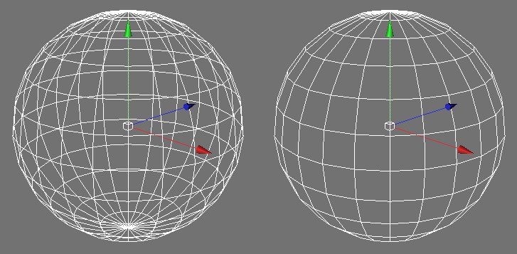 Backface Culling disabled (left) and enabled (right).
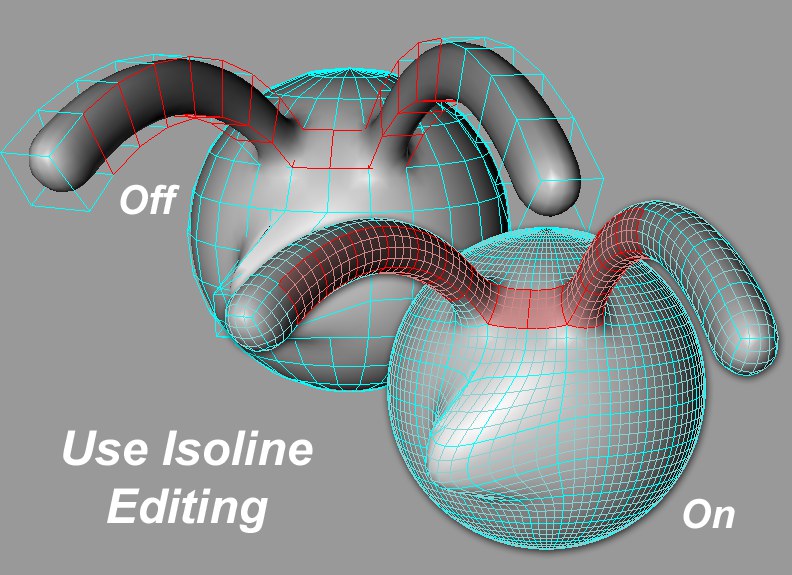
If enabled, all Subdivision Surfaces cage object elements (points, edges, polygons) will be projected onto the smoothed Subdivision Surfaces object so that these elements can be selected directly on the smoothed object.
Even if it looks like you are editing the elements on the smoothed object you are actually only scaling, extruding, cutting, et. the cage object’s elements!
Objects assigned to a layer can be displayed in the editor view in the color of that respective layer. This lets you quickly see which objects have been assigned to which layer.
When in Polygon mode, the display of Polygon Normals can be turned on or off here.
When in Use Point, Use Edge or Use Polygon mode, this option can be used to enable or disable Vertex Normals (see also Vertex Normals).
If this option is enabled, the objects will use the display mode defined in their Display tags (if present). Objects without a Display tag will continue to use the viewport’s shading mode.
Cinema 4D’s real-time texture mapping (RTTM) allows you to see materials/ textures in the view panel in real-time. The Textures option controls whether textures are shown in the viewport (provided the view’s current shading mode can display textures).
This option can be used to turn the material display on or off.
The material display can be turned on or off for each object individually. To do so, create a Display tag in the Object Manager (Object Manager: Render Tags / Display tag).
To activate the X-ray effect, enable this option. If the active object is a polygon object, it will become semi-transparent so that you can see its concealed points and edges. This is particularly helpful with polygon-based modeling, since it enables you to see concealed surfaces in the Gouraud shading and quick shading modes.
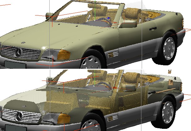 Top: X-ray mode off. Bottom: X-ray mode on.
RELEASE 21
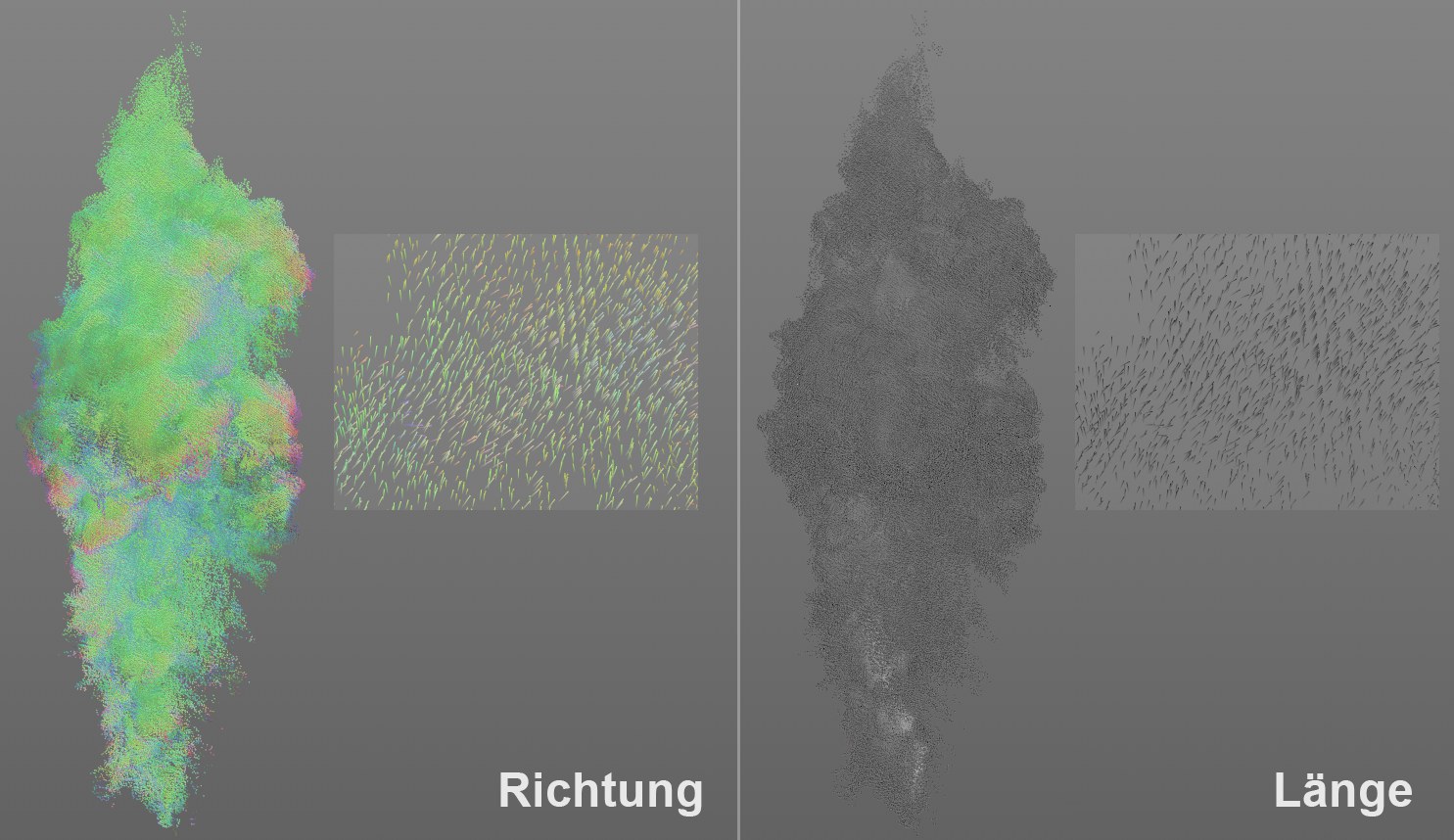
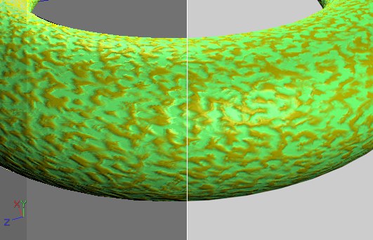
For Volume Vectors, you can define here how they should be displayed in the viewport.
- Direction: The vectors will be colored according to their direction
- Length: The vector length will be used as a visual measure for the vector value (strength): black for smaller, white for greater strength.
In the image above you see the disribution of velocity of the gasses within a fire as volume vectors. In Direction mode you see mostly green vectors and the gasses move primarily upwards along the Y axis. In Length mode, the vectors are colored white near the flames - here especially high velocities take place.
The type of display can also be defined at object level in the Display tag.
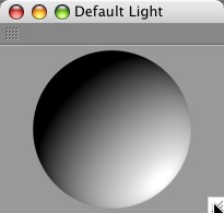
This command opens the Default Light manager. Using this manager you can quickly light the selected objects from any angle. Simply click-drag the shaded sphere to set the lighting to the desired angle (the display mode will change to Quick Shading automatically).
To reset the default light to its original angle, right-click (Windows) or Command-click (macOS) on the shaded sphere. If your scene contains lights, the default light will be ignored when you render.
Each viewport has its own independent default light. The default light settings are saved in the scene file.
The default light is in fact made up of two light sources that are opposite each other. This ensures that the entire scene, not just half, is illuminated. When you render, however, only one of these light sources will be evaluated.