Enhanced OpenGL
Here you will basically find the same visible effects that can be found in the Viewport’s Enhanced OpenGL in the Options menu. The options of the same name correspond with each other and can be defined in either location.
Note that Material Nodes can only be output in a restricted manner with OpenGL (see also Here).
See ![]() Enhanced OpenGL
Enhanced OpenGL
See ![]() Shadows
Shadows
See ![]() Post Effects
Post Effects
See ![]() Transparency
Transparency
See ![]() Noises
Noises
This option can be used to enable or disable the reflection preview for Enhanced OpenGL.
The reflection preview displays a good approximation of the Reflectance channel’s effect in the Viewport without having to render the scene. This is especially advantageous when working with metallic surfaces:
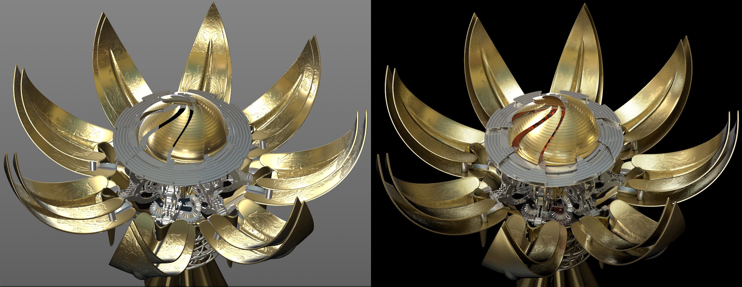 Left: Viewport; right: rendered.
The following applies to reflections of the Sky object (incl. HDRI texture) and the Physical Sky: If no sky is present, an internal substitute object will be used that will be "reflected" (it will not be rendered).
The following applies to sky reflections: The reflection display supports most Reflectance settings, including multiple layers, masks, Fresnel, etc. Textures used to extensively control settings are supported for the most part. A few settings are not supported (Roughness, Bump Strength, Refraction Index).
Reflectance types (e.g., Beckmann, GGX, Phong, etc.) can be defined in the Reflectance channel. The following are supported:
- Beckmann
- GGX
- Phong
- Ward
- Oren-Nayar (Diffuse)
- Lambert (Diffuse)
Anisotropic, Irawan and Reflection (Legacy) are displayed to a lesser degree (and no sky reflection).
The reflection preview (Reflections) can be defined per view in the Viewport Preferences (or also under
With the introduction of Cinema 4D R19, physically correct shading without rendering can be displayed in the Viewport when the Reflectance channel is used. This greatly improves the quality of the display in the Viewport. Among other things, skies and (rectangular) Area lights can be reflected correctly (simplified reflections of other objects will also be displayed).
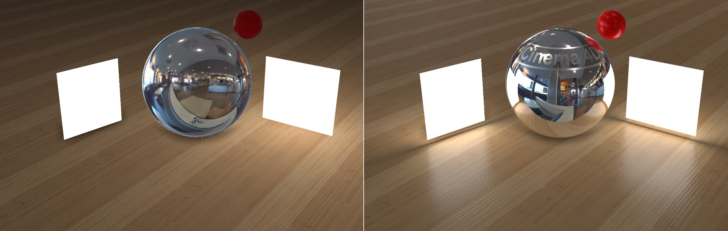 Left Cinema 4D R18, right R19 (each unrendered Viewport displays). Note how the sky’s bright HDRI regions are reflected more clearly, as are various other reflections. The light on the left is a polygon light and on the right an Area light.
With this and the object reflections and depth of field options described below, the Viewport display comes even closer to the rendered result, which means that many a test rendering no longer needs to be done. For simple scenes and scenes that don’t require a rendering you can use the OpenGL option (Renderer Hardware OpenGL) exclusively and forgo test rendering entirely.
Note that when using the Plane primitive object with a luminous material assigned to it - i.e., a polygon light - its behavior will be similar to that of a rectangular Area light (but without shadow casting) and the primitive will be reflected in respective materials.
Load a tecture here for the sky reflection to be used only for the unrendered Viewport display (an invisible Sky object will be used internally). Since there are several locations at which you can define what should reflect in an unrendered object, the following hierarchy applies:
- Material (Editor tab)
- Sky objekt
- Viewport settings (custom HDRI texture on Sky object)
- Internal environment (internal HDRI texture on Sky object)
These values can be used to rotate the Sky object in any direction for the Environment Override.
Screen-Space Local Reflections
The settings described above apply to the reflection of the sky in objects. In order to reflect objects in other objects, the Screen-Space Local Reflections option was added, which uses the graphics card directly for its calculations and is therefore very fast. Of course the results cannot compete with actual rendered reflections but you get a good impression of what they will look like, which in turn speeds up workflow immensely.
The object reflections can generally only reflect items that are in the Viewport, which means that you can run into difficulty with objects that are occluded by others. The back sides of objects that cannot be seen by the camera are also not reflected. Reflections only work if sharp reflections are used (i.e., Roughness = 0).
Reflections work best using this technique when working with water surfaces or floors, i.e., surfaces onto which you generally don’t look directly such as this scene:
 Models by www.Turbosquid.com.
Screen-Space Local Reflections
This options enables or disables the function.
 Left smaller, right larger Ray Distance values.
Use this setting to define the maximum distance the reflection rays can extend until they reach a reflective surface. Smaller values will shorten the reflection accordingly and it will be faded out softly.
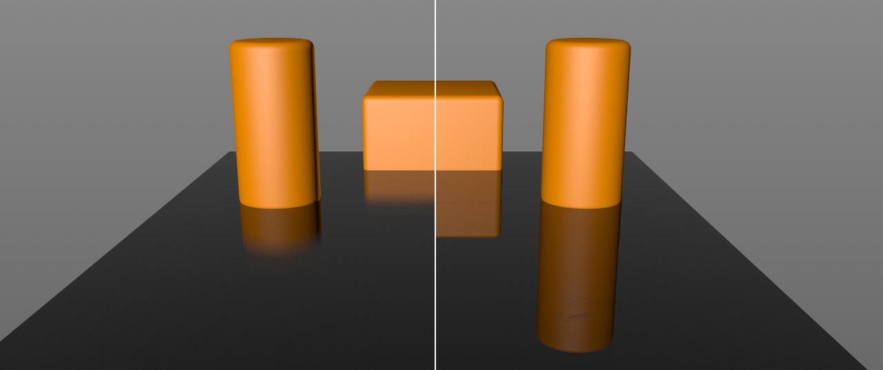
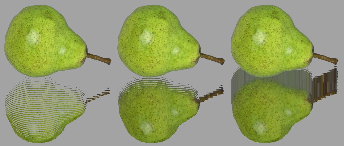 Increasing Geometry Thickness values from left to right.
A detailed description of how this works would be overkill, which is why we created the image above to illustrate. If the values are too small, the depiction will be in slices, if the values are too large "smudging" will occur at neighboring regions above the reflection. Trial and error is required to find the right value.
 Left with, right without SSAO.
SSAO (Screen Space Ambient Occlusion) is a quick approximation of Ambient Occlusion, which is rendered using the graphics card and is visible directly in the Viewport. Since simplified, fast algorithms are used, the result is not identical to the final rendered result.
SSAO is therefore only good for preview purposes in the Viewport and can always be used if you require a higher degree of shading detail in the Viewport. This can be very useful for modeling because it offers a much better preview of the geometry’s topology.
Note that for technical reasons the world grid, world axis and the lines of other non-renderable elements that are shown in the Viewport will be seen as ,geometry’ by SSAO. These should be hidden in the Viewport (Filter menu), if necessary. Furthermore, ,paradoxical’ effects may occur: SSAO darkening can occur on a Floor object at the outer edges of the Viewport.
Enables or disables SSAO for the view.
This setting is a measure for the expanse of the occlusion, i.e., the darkening at inner corners, edges and holes. The smaller the value, the tighter the darkening will hug the respective edge. Larger values will cause the darkening effect to expand correspondingly from the edges until it vanishes at some point.
Simply stated, SSAO works by reading out the depth information of the underlying geometry within a certain radius around a pixel. If differences are ascertained, an occlusion will be assumed and darkening will take place. This is a very simplified approximation to real Ambient Occlusion and will produce false occlusion for very large Depth Range values:
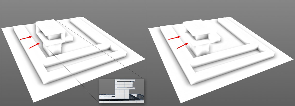 Left larger, right smaller Depth Range value.
Depth Range is a measure of the depth to which a difference in depth should be darkened. This can be seen in the image above in which an occlusion was calculated in the marked areas on the left, even though the structure is not touching the surface below it. The Depth Range at this location is so great that the distance between the surface and the structure’s edge lies within this value. On the right, with the smaller Depth Range value, the value is less than the distance between the two objects.
If very large values are defined, an occlusion will always be rendered where one object occludes another with its edges.
Defines the occlusion’s contrast.
This setting defines the quality of the calculated occlusion. Small values will be calculated faster and provide correspondingly poor quality; larger values will provide correspondingly better results (less grainy and more homogenous) but will also take longer to calculate.
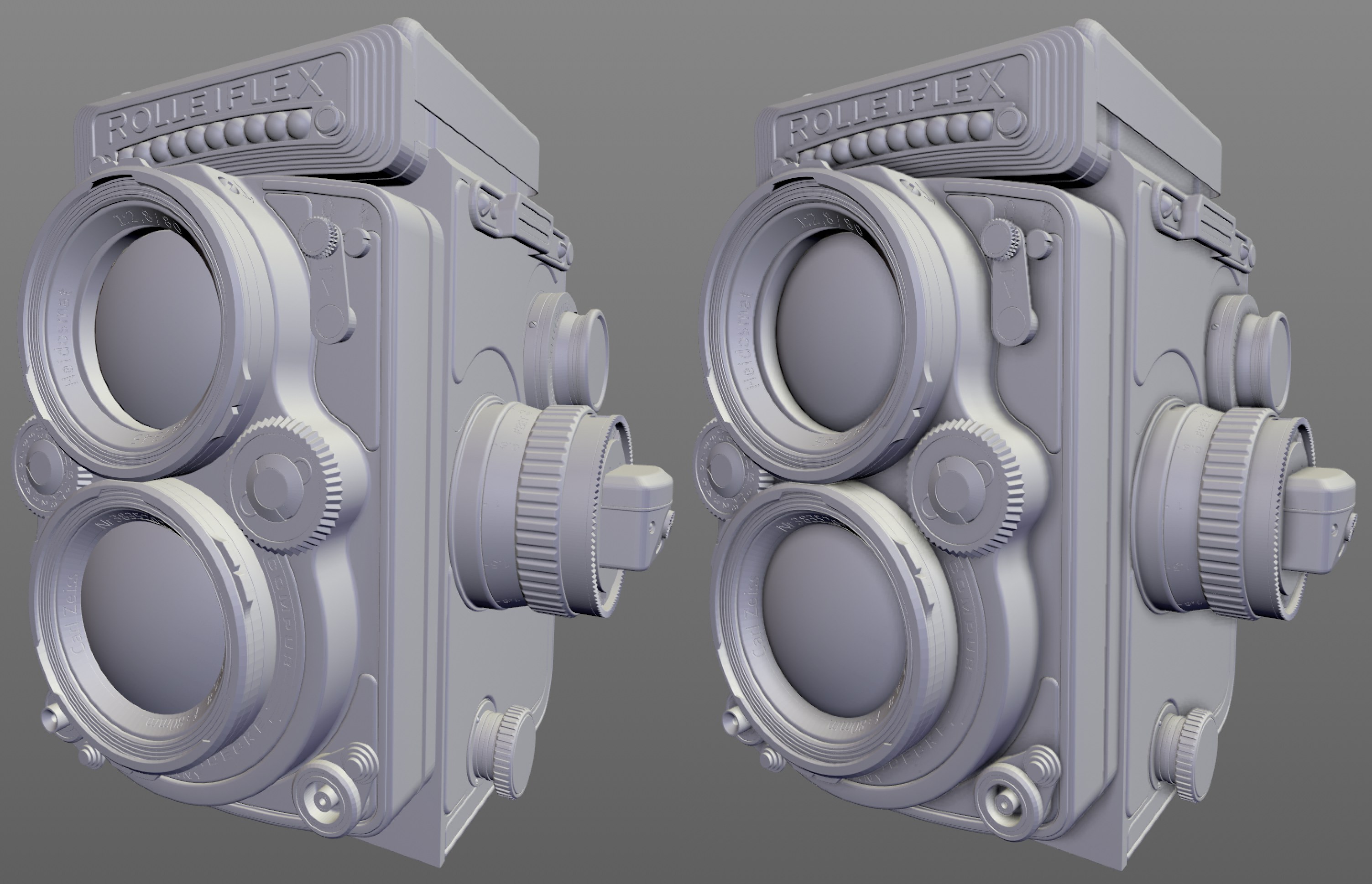
 Left Fine Details disabled, right enabled. Note the darkening around the screws and bolts.
If this option is enabled, a double-sided SSAO calculation will be made internally, whereby the second calculation will be made with a reduced Radius, Depth Range and Power. This will emphasize finer details in particular. This option can be disabled if you already have a very small Radius value (larger values will lead to a more wide-spread darkening with correspondingly less detail).
If enabled, render time will be extended but the otherwise somewhat grainy Ambient Occlusion will be smoothed.
See Tessellation.
 OpenGL Display with activated depth of field.
As with other effects described on this page, depth of field doesn’t strive for absolute realism (there will be deviances between the depth of field of the Phyiscal Renderer and ProRender). Basically, the scene depiction will be blurred in relation to the depth information. Camera settings such as F-Stop, Sensor Size and of course Focal Distance will be taken into consideration in order to create a depth of field that is as realistic-looking as possible (general information can be found under (Depth Of Field).
Bokehs will receive special attention: Settings for Bokeh display in the Camera object primarily affect the Bokeh shape (s. Diaphragm Shape).
In many cases, the Aperture (f#) has to be reduced for the camera through which the scene is viewed to create a visible depth of field.
This value defines the maximum blur radius (comparable with the blur tool radius in Photoshop, for example). Object regions that lie closer to the camera’s focal distance will then be given a smaller radius, which will fall to 1 at the focal distance plane. The farther objects lie from the focal distance plane - up to the maximum defined radius - the more blurred they will be.