Display
These settings mostly control how active and inactive objects will be displayed in the viewport.
Here you can change the view’s name. This is the name displayed by default in the HUD.
![]() Active Object
Active Object
This is where you define how objects should be displayed in the editor view (these settings correspond to those of the
Objects that have been assigned to layers can be displayed in the color of the layer to which they have been assigned.
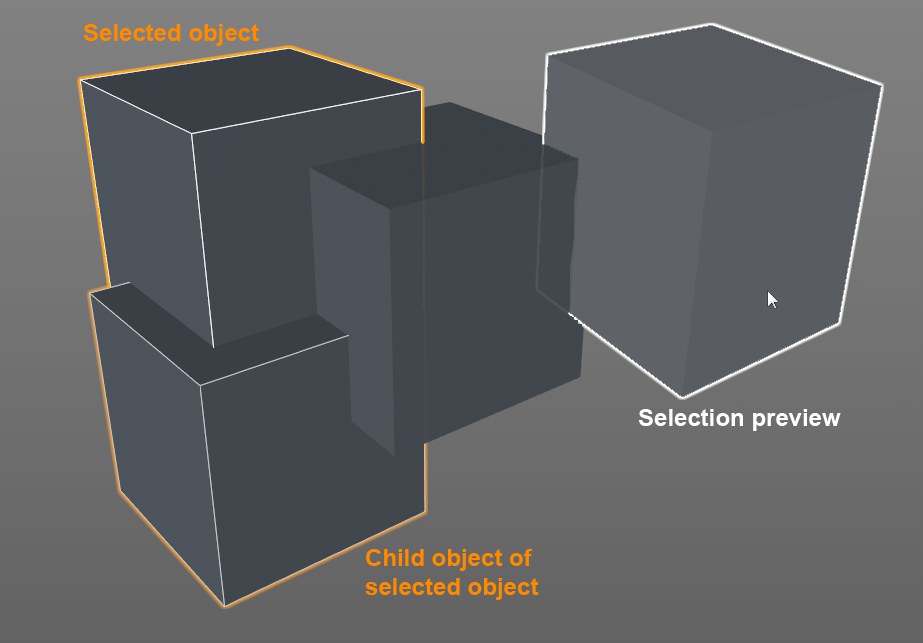
Selected objects or objects to be selected can be highlighted with a colored outline (the outline thickness can be adjusted using the Highlight Outline Width setting).
Objects over which you hover with the cursor (without clicking on them) will be given a white outline, depending on the tool or mode that is currently active (e.g., Move tool in Use Model mode). This helps greatly when selecting interactively (especially when using the Tweak mode for objects).
The Child objects of selected objects will be outlined with a thinner outline.
The outline can be disabled globally (the
Note that the outline display will only work with activated
These settings define the display mode used for active objects.
Gouraud Shading
Gouraud Shading (Lines)
The highest quality display mode for viewports. All objects are shaded with smoothing and light sources are taken into account. The redraw rate is affected most by processor speed and graphics card speed — the faster your CPU and graphics display card, the faster scenes will redraw. If the display update becomes too slow, try reducing the size of the viewport..
In this mode you can add wireframes or isoparms to the Gouraud shading by choosing Wireframe or Isoparms from the
Quick Shading
Quick Shading (Lines)

This is almost identical to Gouraud Shading. The difference is that the auto light is used instead of the scene’s lights to calculate the shading. This can lead to a faster redraw rate.
In this mode you can add wireframes or isoparms to the Quick shading by choosing Wireframe or Isoparms from the
Constant Shading
Constant Shading (Lines)
This option lets you display constant shading only or constant shading in conjunction with the wire frame.
In contrast to Lines mode, hidden lines are not displayed.

The Lines mode allows the complete display of the polygon mesh including hidden lines.

The wireframe mode draws lines on the objects if combined with a mode that allows this such as Gouraud Shading (Lines).

This mode displays isoparm lines for objects that use them such as Generator objects. Other objects such as polygon objects will be displayed in wireframe. This mode will only have an effect if used in combination with a mode that supports it such as Gouraud Shading (Lines).
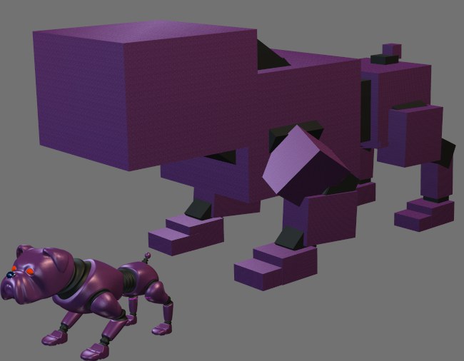
This mode displays each object as a box. Each box has the same dimensions as the object it represents. Box is the second fastest display mode available, making it useful for extremely demanding scenes.
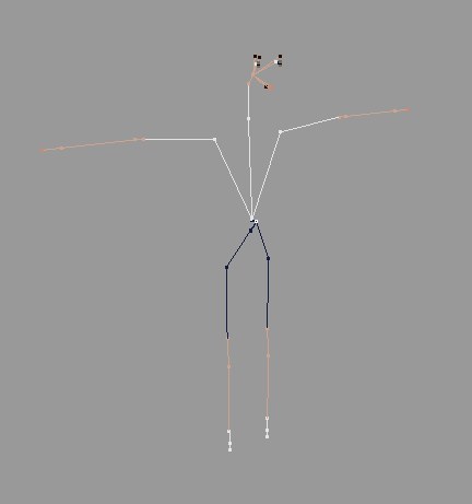
This is the fastest display mode of all. It is only suitable for hierarchical structures. Each object origin is shown as a small dot and the dots are connected according to the hierarchy. This mode can be useful for character animation. Not only is it extremely fast, it also removes all non-critical lines to expose the skeleton
If this option is enabled, the objects will use the display mode defined in their Display tags (if present). Objects without a Display tag will continue to use the viewport’s shading mode.
If you enable this option, surface Normals will be displayed in the viewport for the selected polygons. Each normal is displayed as a small auxiliary line perpendicular to the polygon’s surface. By convention, the direction of a normal represents the direction of its polygon. In the Options menu you will find a command with which this option can be enabled or disabled.
For example, backface culling checks the direction of each normal to determine whether its surface should be drawn — if the normal points away from the camera, the surface is not drawn (the surface is assumed to point away from the camera, just like its normal).
Disable this option to display all polygon Normals of the selected objects.
Use these settings to define whether or not Vertex Normals should be displayed in Use Point, Edge or Polygon mode (in the Viewport’s Option menu you will find an option for enabling or disabling this feature). When in Use Polygon mode, Selected Only will display Vertex Normals that belong to selected polygons. If this option is disabled, all Vertex Normals will be displayed in all 3 component modes.
As you know, polygon normals are an element of every polygon. A polygon normal is a vector that lies perpendicular to each polygon. Vertex Normals are normals at each of a (non-smoothed) polygon’s points. Each polygon point can have 1 to 4 Vertex Normals, depending on the number of polygons to which it belongs.
These Vertex Normals are evaluated for each visible surface point for shading/rendering and interpolated at this location to produce a soft, homogenous shading.
Currently, displaying surface Normals only serves informational purposes since they cannot be edited comfortably.
You can, however, influence them indirectly, e.g., by applying Use Edge Breaks or modifying the Angle Limit in the Phong tag’s settings:
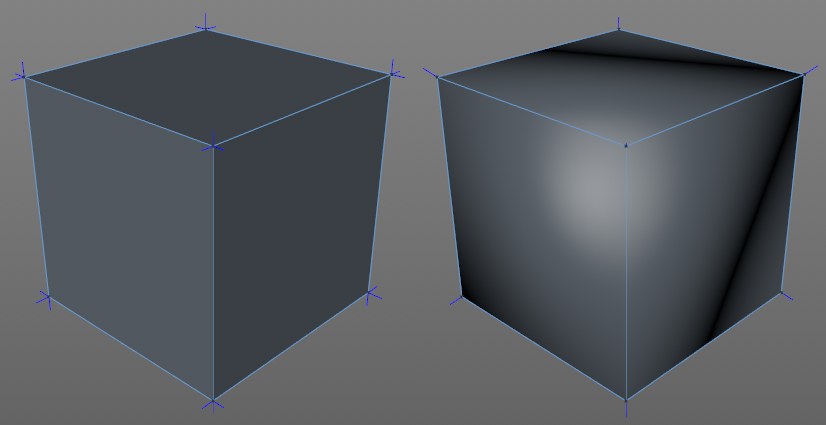 Left no smoothing, right smoothing via the Phong tag.
In the image above, the shading on the left is not smoothed using the Phong tag; on the right smoothing with a Phong Angle of 90°. On the right, are 3 overlapping Vertex Normals. If an interpolation between these three is made for shading, the smoothing as shown, in which the shading edges are removed, will be produced. The result is shading as it would appear on a sphere.
Normal tags that are normally imported with CAD formats, can set by Vertex Normals, independent of surface Normals in order to achieve a better shading (than the automatic procedure described above). By using Normal tags, Vertex Normals can also be displayed numerically in the Structure Manager (
Enable this option to display the active object’s animation path as a Spline curve in the viewport. Edit the animation path as you would a spline, i.e., drag curve points to new positions. The tangents cannot be edited. Editing the animation path in this way allows you to adjust it without having to edit the keys.
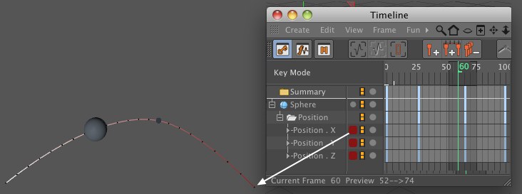
The color of the animation path is taken from the animation track’s Timeline layer color. This makes it easier to differentiate animation paths when they each have their own color.
The length of the animation path displayed in the Viewport is now in direct relation to the preview range, i.e., if the preview range is short, a correspondingly short section of the animation path will be shown. Drag the preview range to the complete Project length to display the entire animation path (
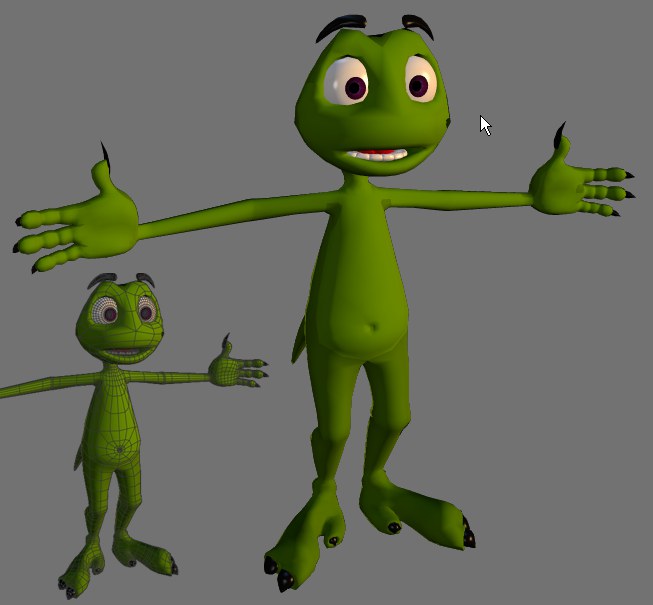
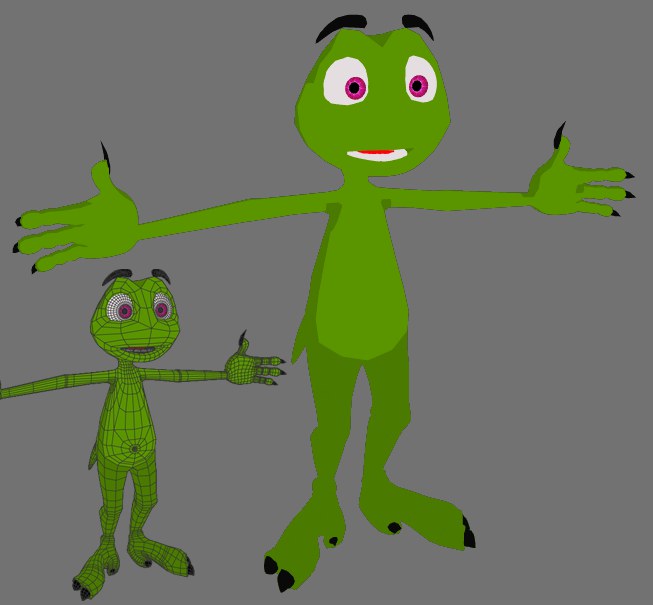
To enter X-Ray mode, enable this option. If the active object is a polygon object, it will become semi-transparent so that you can see all of its points and edges.
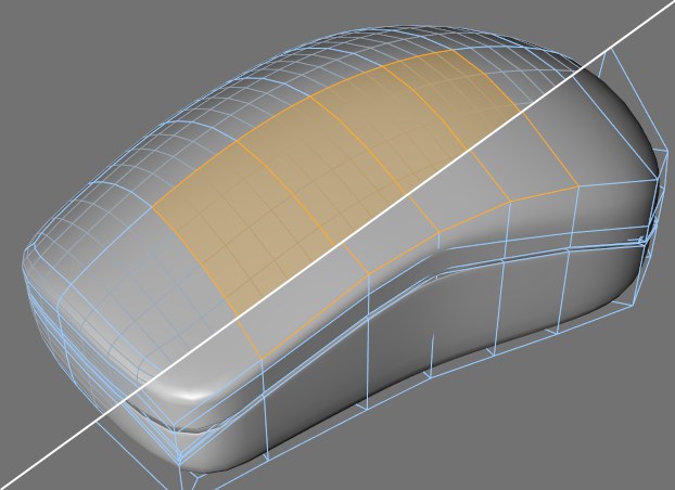 Isoline Editing enabled (top) and disabled (bottom).
If this option is enabled, all the elements of the Subdivision Surfaces cage object — i.e., its points, edges and polygons — will be projected onto the smoothed Subdivision Surfaces object. This allows you to select these elements directly on the smoothed object. Although it may look like you are selected smoothed parts of the object, you are, in fact selecting cage elements!
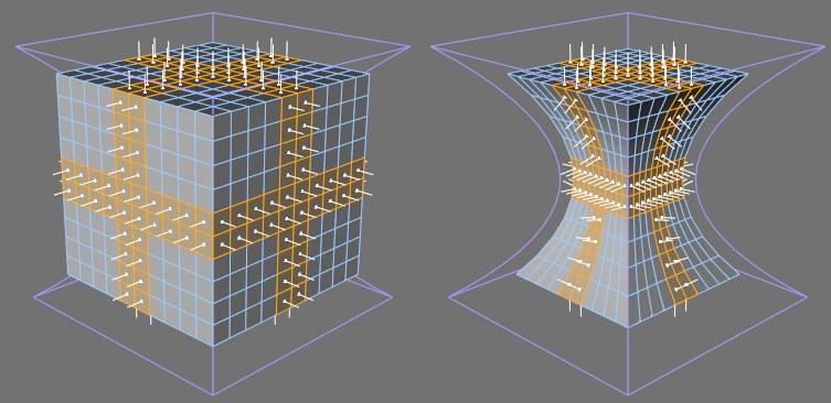 A cube deformed by a Bulge object with Deformed Editing disabled (left) and enabled (right).
If it frustrates you when you edited a polygon object that is being deformed by a deformer and the polygon object reverts to its non-deformed state as soon as you change to point, edge or polygon mode, now Cinema 4D allows you to edit polygon objects while they are still in the deformed state — simply enable the Deformed Editing option.
If you want object points to be displayed while you are working in edge mode, enable this option.
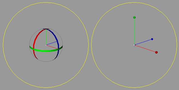 Rotation Bands enabled (left) and disabled (right).
Here you can choose whether either rotation bands or spherical handles are displayed for the selected objects when the Rotate tool is selected.
Sel.: Bounding Box
Include Children
Sel.: Wireframe
Include Children
Here you can define how active objects and their children should be displayed in the viewport: in wireframe, with a bounding box or both.
Here you can define how selected volume vectors are displayed at the Viewport level. For details see Volume Vectors.
![]() Inactive Object
Inactive Object
Enable this option if you want the inactive objects to be displayed using different modes to the ones specified on the viewport’s
These settings define the display mode used for inactive objects.
If this option is enabled, the inactive objects will use the display mode defined in their Display tags (if present) instead of the setting defined here in the viewport settings.
Here you can define how non-selected Volume Vectors are displayed at the Viewport level. For details see Volume Vectors.