Effects
The Default command can be used to set the Viewport settings back to it default settings.
Here you will for the most part find the same visible effects that can be found in the Viewport’s Effects in the Options menu. The options of the same name correspond with each other and can be defined in either location.
Here in the Viewport’s Configure menu, there are several more settings that, for example, can be used to define the SSAO details (these can be opened by clicking on the small arrow).
See ![]() Effects.
Effects.
Enables/disables shadows.
A shadow map will be calculated in the Viewport independently of the shadow type defined for the light source - even for hard shadows defined for the light source. In the Viewport, these shadows will nevertheless look hard thanks to a render trick. You should already be familiar with shadow maps from the Standard Renderer (see also Shadow Map). The shadow quality (and with it the render time and memory requirements) will increase accordingly with larger shadow maps.
Generally speaking, if you want hard or soft shadows, this should be defined in the light source’s General menu under Shadow (Shadow Maps and Area will both be rendered identically as soft shadows in the Viewport). Don’t expect any miracles, though - the shadows will not hold up to real, rendered shadows.
Soft Shadow Attenuation[0.01..10000.00]
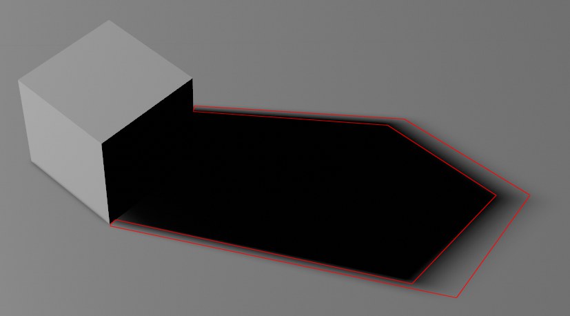
This setting can best be seen in conjunction with soft shadows. Take a look at the transition area marked in red in the image above in which the shadow is reduced. This transition area, which gets smaller as the shadow map’s size increases, can be adjusted using the Soft Shadow Attenuation setting as follows: higher values will produce correspondingly stronger, more dense shadows and vice-versa.
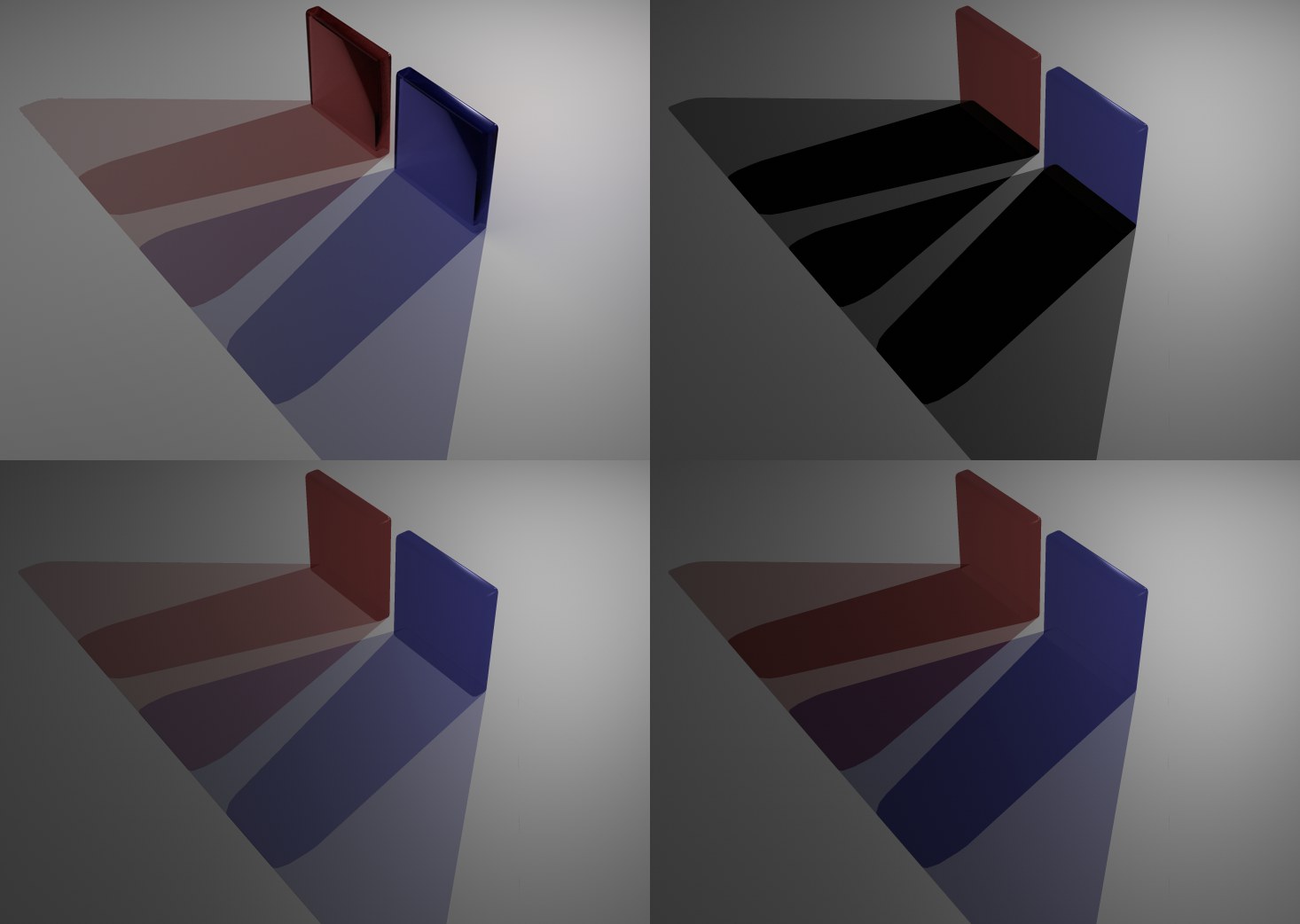 Clockwise from the top left: Standard Renderer, Viewport Renderer with Shadow Type set to Opaque, Colored, Colored Layered.
Objects to which an active Transparency channel has been assigned generate a shadow dependent on the transparency, which can be colored - like with colored glass.
Several shadow types can be rendered in the Viewport, whereby the quality and render time increased from top to bottom:
- Opaque: Shadows will be rendered as though the transparent material is opaque.
- Colored: Opacity and color of the transparent material will be taken into consideration. Multiple overlapping shadows will, however, not be rendered correctly.
•Colored Layered: Like Colored but overlapping shadows will be rendered correctly (see top left and bottom left of image). Note that a maximum of two layered shadows can be rendered correctly.
In previous versions of Cinema 4D (prior to S22), Shadowmap Size was defined internally to 2048 and couldn’t be changed. Now, this can be defined freely within a certain range. Increase the value carefully because values that are too high can really bog down the display speed.
Generally speaking, the following can be said about Shadowmap Size: The larger the shadow map, the harder and more precise the shadows will be (an the correspondingly slower the display speed will be).
If the shadows are jagged or cut off, the Shadowmap Size value is too low.
If banding occurs when shadow casting lights are rendered, enabling or disabling this option can help:
See ![]() Post Effects.
Post Effects.
Here you can define whether or not high-quality transparencies should be displayed.
Complete Material Transparency
Here you can define if transparencies should also be displayed as completely transparent if the Transparency material channel is completely transparent (whereby the object will be completely invisible due to the missing refraction display). If this option is disabled, only an 80% transparency will be displayed.
See ![]() HQ Noises.
HQ Noises.
Reflection Preview
This option can be used to enable or disable the reflection preview for the Viewport.
The reflection preview displays a good approximation of the Reflectance channel’s effect in the Viewport without having to render the scene. This is especially advantageous when working with metallic surfaces:
 Left: Viewport; right: rendered.
The following applies to reflections of the Sky object (incl. HDRI texture) and the Physical Sky: If no sky is present, an internal substitute object will be used that will be "reflected" (it will not be rendered).
The following applies to sky reflections: The reflection display supports most Reflectance settings, including multiple layers, masks, Fresnel, etc. Textures used to extensively control settings are supported for the most part. A few settings are not supported (Roughness, Bump Strength, Refraction Index).
Reflectance types (e.g., Beckmann, GGX, Phong, etc.) can be defined in the Reflectance channel. The following are supported:
- Beckmann
- GGX
- Phong
- Ward
- Oren-Nayar (Diffuse)
- Lambert (Diffuse)
Anisotropic, Irawan and Reflection (Legacy) are displayed to a lesser degree (and no sky reflection).
The reflection preview (Reflections) can be defined per view in the Viewport Preferences (or also under ).
With the introduction of Cinema 4D R19, physically correct shading without rendering can be displayed in the Viewport when the Reflectance channel is used. This greatly improves the quality of the display in the Viewport. Among other things, skies and (rectangular) Area lights can be reflected correctly (simplified reflections of other objects will also be displayed).
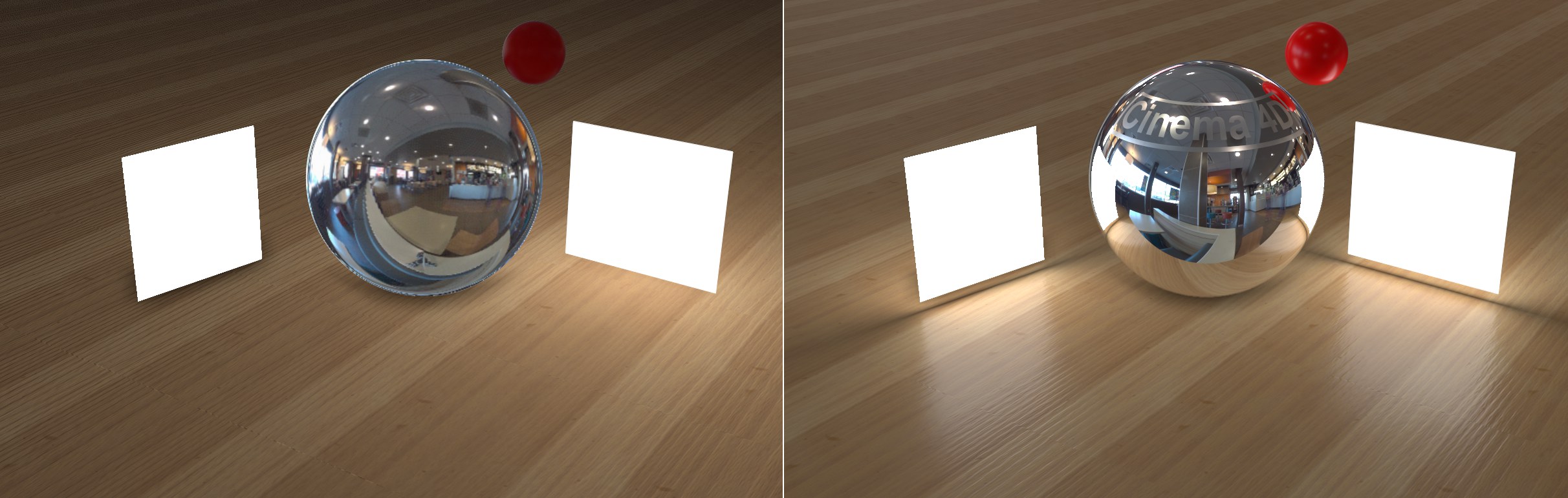 Left Cinema 4D R18, right R19 (each un-rendered Viewport displays). Note how the sky’s bright HDRI regions are reflected more clearly, as are various other reflections. The light on the left is a polygon light and on the right an Area light.
With this and the object reflections and depth of field options described below, the Viewport display comes even closer to the rendered result, which means that many a test rendering no longer needs to be done. For simple scenes and scenes that don’t require a rendering you can use the hardware option (Renderer Viewport Renderer) exclusively and forgo test rendering entirely.
Note that when using the Plane primitive object with a luminous material assigned to it - i.e., a polygon light - its behavior will be similar to that of a rectangular Area light (but without shadow casting) and the primitive will be reflected in respective materials.
Load a tecture here for the sky reflection to be used only for the un-rendered Viewport display (an invisible Sky object will be used internally). Since there are several locations at which you can define what should reflect in an un-rendered object, the following hierarchy applies:
- Material (Editor tab)
- Sky object
- Viewport settings (custom HDRI texture on Sky object)
- Internal environment (internal HDRI texture on Sky object)
These values can be used to rotate the Sky object in any direction for the Environment Override.
Screen-Space Local Reflections
The settings described above apply to the reflection of the sky in objects. In order to reflect objects in other objects, the Screen-Space Local Reflections option was added, which uses the graphics card directly for its calculations and is therefore very fast. Of course, the results cannot compete with actual rendered reflections but you get a good impression of what they will look like, which in turn speeds up workflow immensely.
The object reflections can generally only reflect items that are in the Viewport, which means that you can run into difficulty with objects that are occluded by others. The back sides of objects that cannot be seen by the camera are also not reflected.
The quality of screen-space reflections was improved in Cinema 4D R23. These now also work in larger scenes. Furthermore, material roughness is also supported, i.e., matte reflections work via a simplified approximation:
However, there are limitations: Object borders will still produce hard reflections.
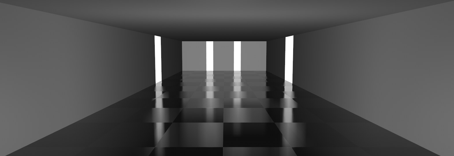
Reflections work best using this technique when working with water surfaces or floors, i.e., surfaces onto which you generally don’t look directly such as this scene:
 Models by www.Turbosquid.com.
Screen-Space Local Reflections
This option enables or disables the function.
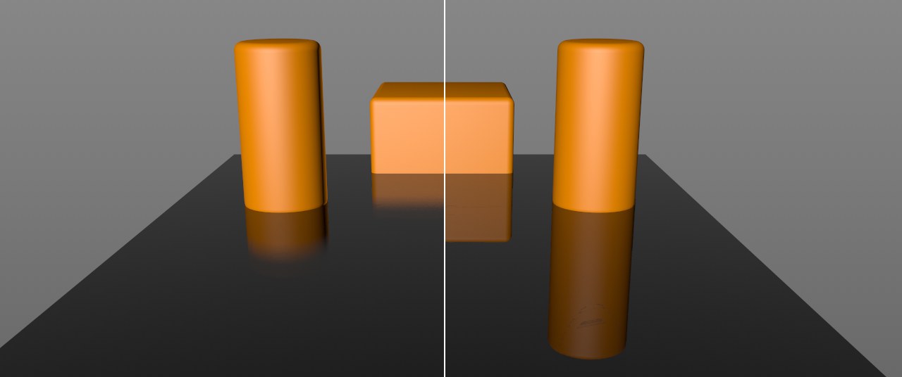 Left smaller, right larger Ray Distance values.
Use this setting to define the maximum distance the reflection rays can extend until they reach a reflective surface. Smaller values will shorten the reflection accordingly and it will be faded out softly.
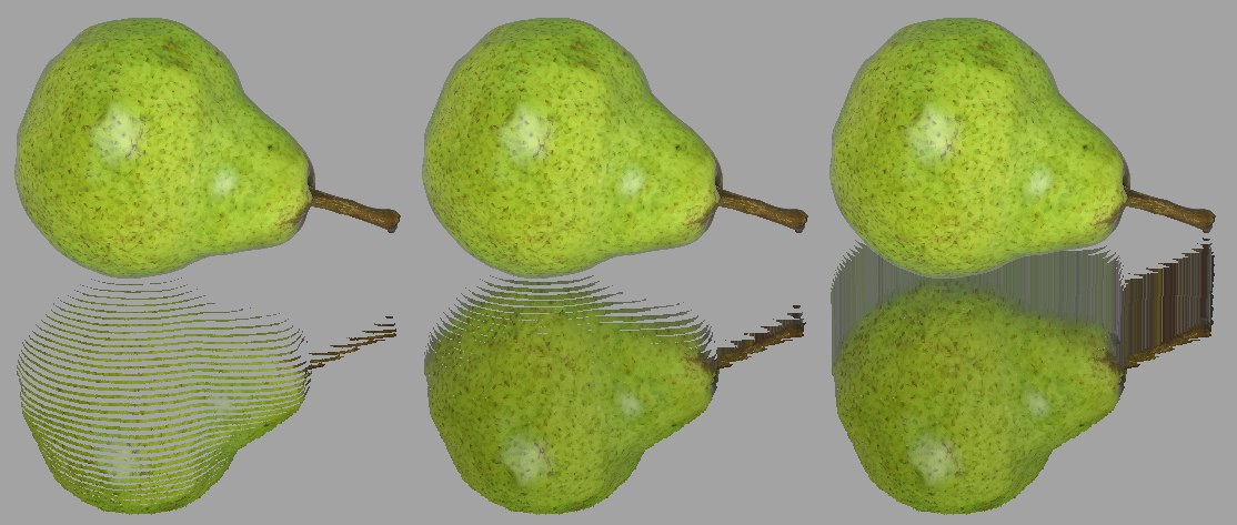 Increasing Pixel Thickness values from left to right.
A detailed description of how this works would be overkill, which is why we created the image above to illustrate. If the values are too small, the depiction will be in slices, if the values are too large "smudging" will occur at neighboring regions above the reflection. Trial and error is required to find the right value.
Enabling this option will increase render speed but reduce quality accordingly (as the name suggests …). Fewer samples will be sent into the scene. This is particularly useful when using a high-resolution monitor (e.g., Retina).
See ![]() Magic Bullet Looks.
Magic Bullet Looks.
SSAO
 Left with, right without SSAO.
SSAO (Screen Space Ambient Occlusion) is a quick approximation of Ambient Occlusion, which is rendered using the graphics card and is visible directly in the Viewport. Since simplified, fast algorithms are used, the result is not identical to the final rendered result.
SSAO is therefore only good for preview purposes in the Viewport and can always be used if you require a higher degree of shading detail in the Viewport. This can be very useful for modeling because it offers a much better preview of the geometry’s topology.
Enables or disables SSAO for the view.
This setting is a measure for the expanse of the occlusion, i.e., the darkening at inner corners, edges and holes. The smaller the value, the tighter the darkening will hug the respective edge. Larger values will cause the darkening effect to expand correspondingly from the edges until it vanishes at some point.
Simply stated, SSAO works by reading out the depth information of the underlying geometry within a certain radius around a pixel. If differences are ascertained, an occlusion will be assumed and darkening will take place. This is a very simplified approximation to real Ambient Occlusion and will produce false occlusion for very large Depth Range values:
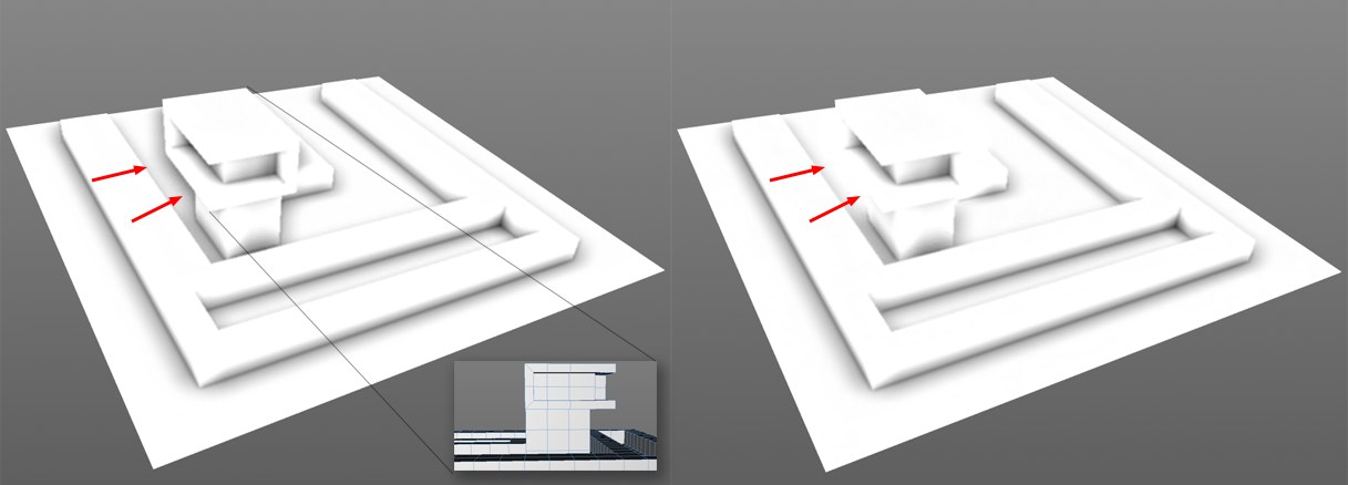 Left larger, right smaller Depth Range value.
Depth Range is a measure of the depth to which a difference in depth should be darkened. This can be seen in the image above in which an occlusion was calculated in the marked areas on the left, even though the structure is not touching the surface below it. The Depth Range at this location is so great that the distance between the surface and the structure’s edge lies within this value. On the right, with the smaller Depth Range value, the value is less than the distance between the two objects.
If very large values are defined, an occlusion will always be rendered where one object occludes another with its edges.
Defines the occlusion’s contrast.
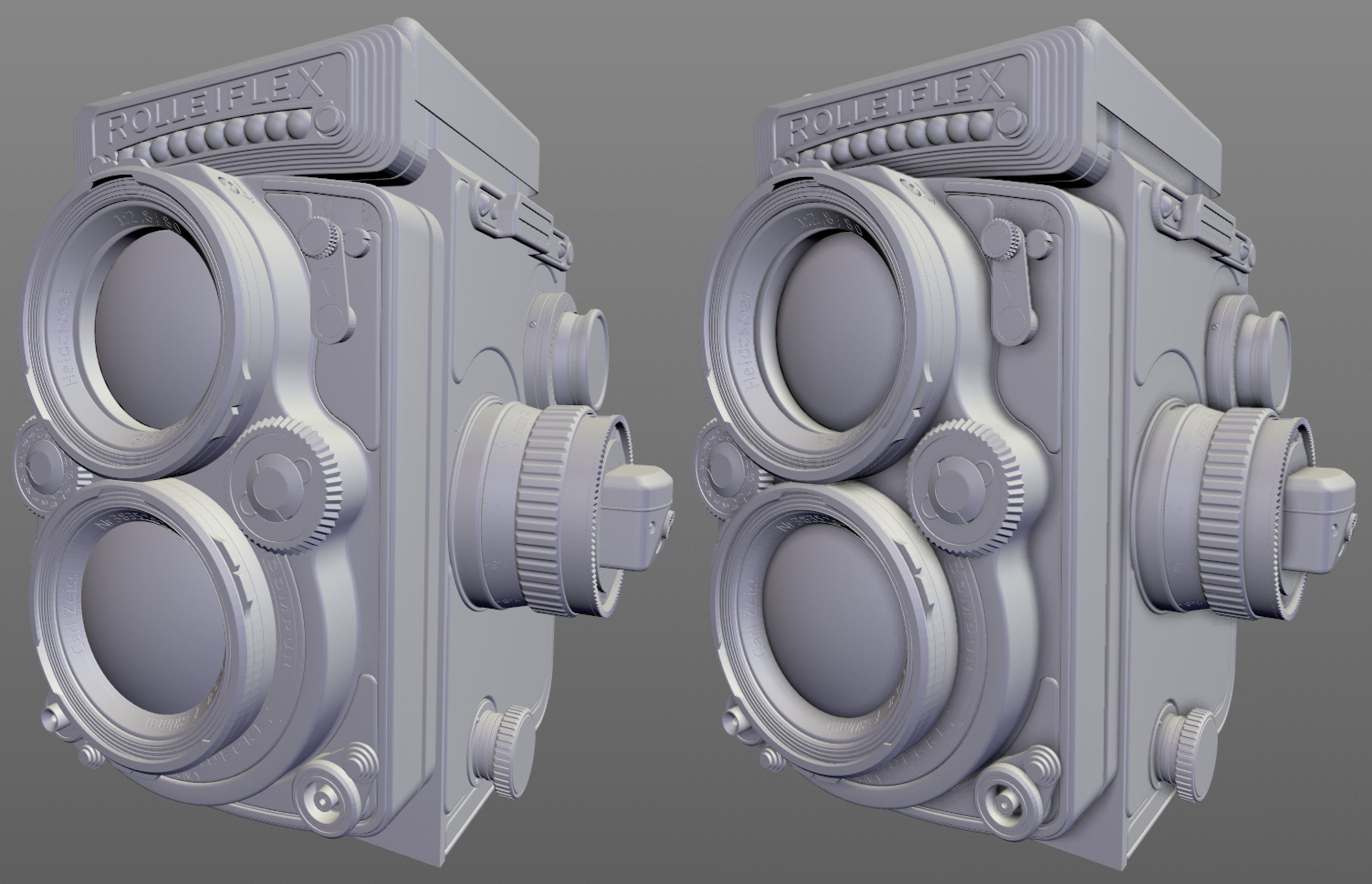
This setting defines the quality of the calculated occlusion. Small values will be calculated faster and provide correspondingly poor quality; larger values will provide correspondingly better results (less grainy and more homogenous) but will also take longer to calculate.
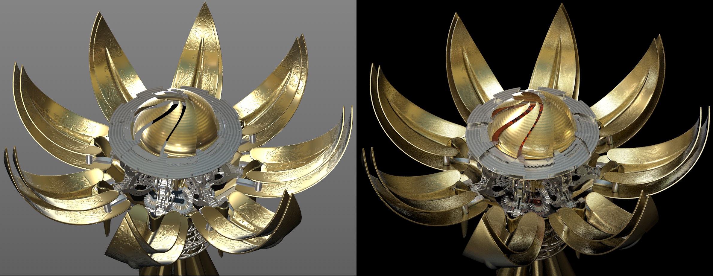
 Left Fine Details disabled, right enabled. Note the darkening around the screws and bolts.
If this option is enabled, a double-sided SSAO calculation will be made internally, whereby the second calculation will be made with a reduced Radius, Depth Range and Power. This will emphasize finer details in particular. This option can be disabled if you already have a very small Radius value (larger values will lead to a more wide-spread darkening with correspondingly less detail).
If enabled, render time will be extended but the otherwise somewhat grainy Ambient Occlusion will be smoothed.
You can select from the following modes:
- Per Material: SSAO will also affect other material channels (such as Luminance/Reflectance for Standard/Physical materials and Attenuation/Reflection for Node Uber materials). If SSAO should also be visible on luminating or reflective materials (which is less realistic), this option should be enabled.
- Diffuse: SSAO will only affect the diffuse portion of the material and will not take other material channels into consideration. This is the desired behavior in most cases.
See Tessellation.
 Display with activated depth of field.
As with other effects described on this page, depth of field doesn’t strive for absolute realism (there will be deviances between the depth of field of the Phyiscal Renderer and ProRender). Basically, the scene depiction will be blurred in relation to the depth information. Camera settings such as F-Stop, Sensor Size and of course Focal Distance will be taken into consideration in order to create a depth of field that is as realistic-looking as possible (general information can be found under (Depth Of Field).
Bokehs will receive special attention: Settings for Bokeh display in the Camera object primarily affect the Bokeh shape (s. Diaphragm Shape).
This value defines the maximum blur radius (comparable with the blur tool radius in Photoshop, for example). Object regions that lie closer to the camera’s focal distance will then be given a smaller radius, which will fall to 1 at the focal distance plane. The farther objects lie from the focal distance plane - up to the maximum defined radius - the more blurred they will be.
What is this setting good for? If this option is disabled, the depth of field will only affect pixels that are already blurred (and not the anti-aliasing samples, of which there are many more) and makes it possible - at slightly lower quality - to render the view much faster.
There are, however, cases in which enabling the option is recommended because strong artefacting can occur:
 Left: option enabled; right: disabled Evaluate Anti-Aliasing option (all dust grains create a Bokeh effect).
See Supersampling.
Be careful with higher values because the Viewport can be slowed down considerably!
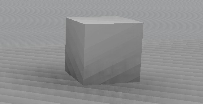
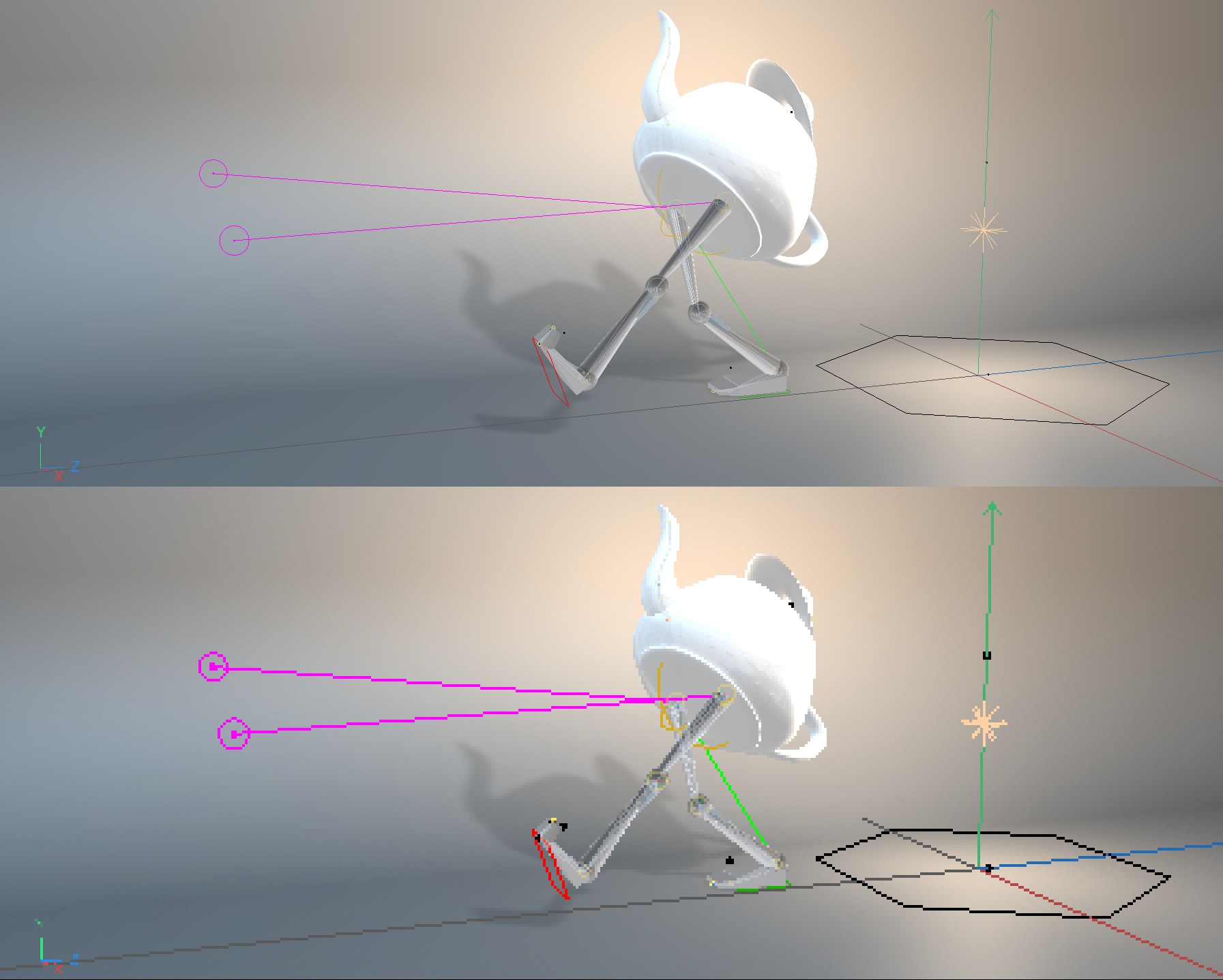 Top: normal Resolution of 1; bottom 1/8.
If the Viewport display is too slow, you can reduce the resolution here to speed it up. The reduced rendered view will then simply be scaled up to full-screen. 1/8 means that an area of 8*8 pixels will be rendered as a single pixel.
You sacrifice quality for speed.