Tag Properties
You can assign a material to the Material tag by dragging the material from the Material Manager and dropping it into this box. If multiple Texture tags are selected, the material will be applied to all of them. If you click the triangle button next to the material box, a menu will appear with the following commands:
This field can be animated to morph materials, i.e., blend stepplessly from one material to another.
Clear
Removes the Material tag’s material.
Show In Manager
Displays the Material tag’s material in the Material Manager.
Select Element
Selects the Material tag’s material in the Material Manager.
Selection enables you to use different materials on different parts of the same object. This is a convenient way to add, for example, labels to objects. First of all you need a Selection tag. You can also enter a name (Selection tag’s Basic tab) by simply dragging the tag into this field.
This function works hierarchically, which means a Material tag with a defined Selection field projects the material onto all Child objects with a corresponding Selection tag.
You can read more regarding selections here.
Note also the hidden selections of specific Generators (e.g., Extrude object, Text object, etc) as described here, for example.
The Offset and Length settings define the position and size of the texture in the X and Y directions on the texture envelope. For example, if Length X and Length Y are both set to 100%, the texture covers the envelope completely.
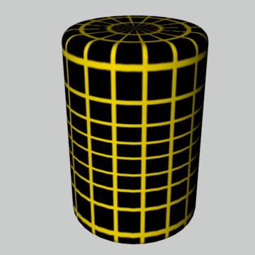
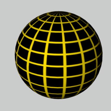
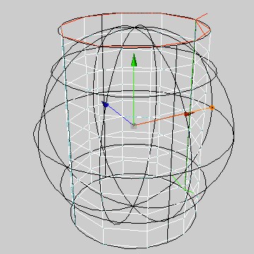
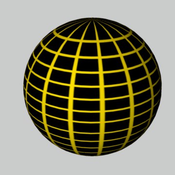
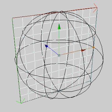
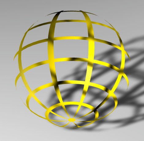
Spherical mapping projects the texture onto the object in a spherical form.
 Spherical applied to a plane. Spherical applied to a plane.
|
|
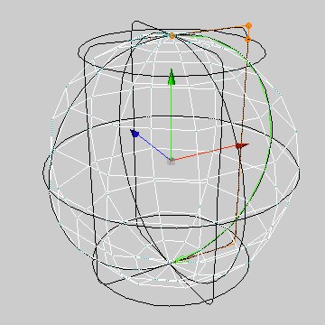 Spherical applied to a cylinder. Spherical applied to a cylinder.
|
|
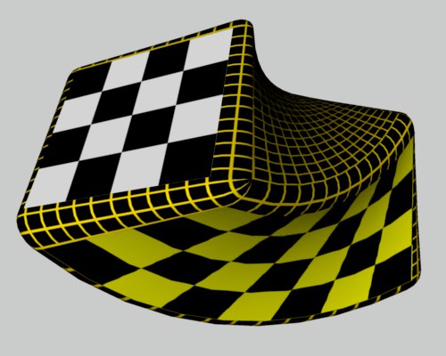
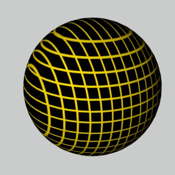
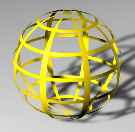
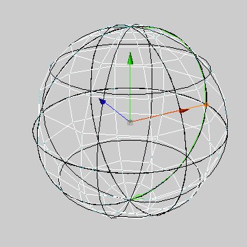 Spherical applied to a sphere. Spherical applied to a sphere.
|
|
Spherical projection is rarely suitable for flat objects. There is distortion with cylindrical objects also.
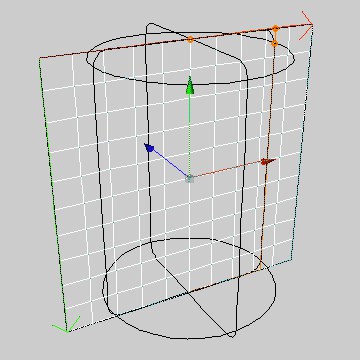
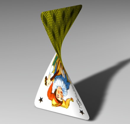
This mapping type projects the texture onto the object in a cylindrical shape.
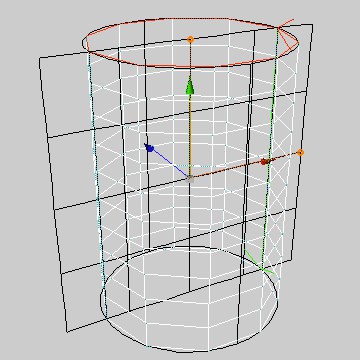 Cylindrical applied to a plane. Cylindrical applied to a plane.
|
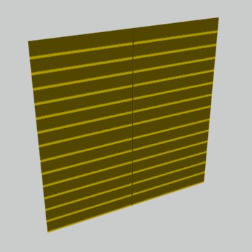
|
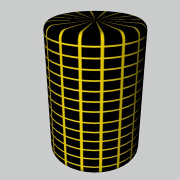
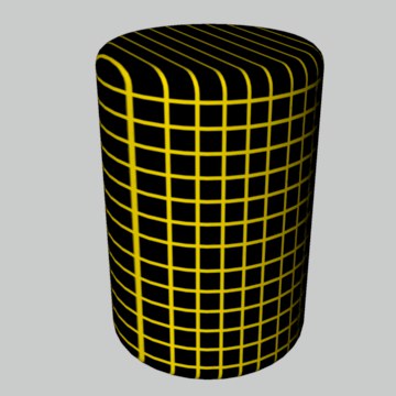
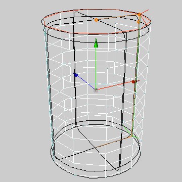 Cylindrical applied to a cylinder. Cylindrical applied to a cylinder.
|
|
 Cylindrical applied to a sphere. Cylindrical applied to a sphere.
|
|
Cylindrical projection is rarely suitable for flat objects. It also leads to distortion when used with spherical objects. When Cylindrical is applied to a cylinder, notice how the pixels near the top and bottom of the texture map are pulled inwards on the caps. You should apply separate textures to the caps.
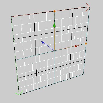
Flat mapping projects the texture onto the object in a planar direction.
|
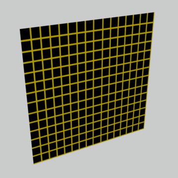 Flat mapping applied to a plane. Flat mapping applied to a plane.
|
 Flat mapping applied to a cylinder. Flat mapping applied to a cylinder.
|
|
 Flat mapping applied to a sphere. Flat mapping applied to a sphere.
|
|
Flat projection tends to be used with flat objects only. The texture is soon distorted when applied to a sphere or cylinder, as the examples demonstrate.
Cubic mapping projects the texture onto all six sides of a texture cube.
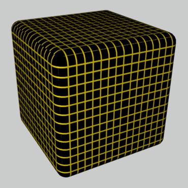 Cubic applied to a cuboid.
The texture is projected from the camera position onto the object. This ensures that, it you project the texture onto a Polygon object and onto a Background object, the two textures match exactly (assuming the Material tags for both objects use the same Offset and Length values).
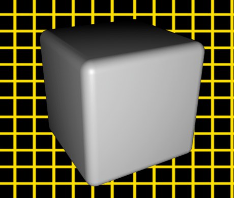 Frontal applied to a cuboid.
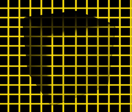
You can create various visual effects using Frontal mapping, or perform compositing tricks directly in Cinema 4D.
You have probably seen science fiction films where characters or spaceships gradually blend into the background using cloaking. Use Frontal mapping for such effects. For another interesting effect, remove the Background object and move the polygon around!
Spatial mapping is similar to Flat projection. However, with Spatial mapping, the texture is pulled up and to the left as it passes through the object.
 Flat Flat
|
 Spatial Spatial
|
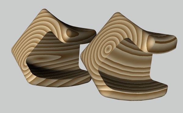
Spatial mapping does, however, cause some distortion and as such it is not suitable for photographic images. Spatial mapping is more suitable for structural textures, such as plaster and marble.
If an object has UVW coordinates, you can select them as the projection type. In this case, the texture geometry is fixed to the object surface and is subject to all subsequent movement and deformation applied to the object. UV projection is explained in the menu.
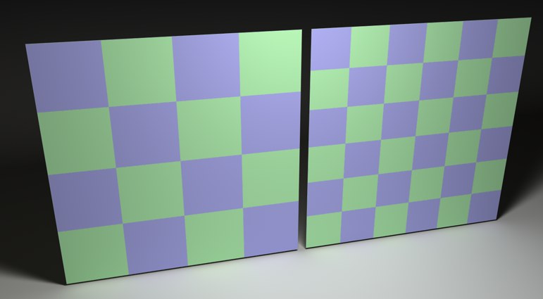
An example of UVW mapping is the page of a book as it is being turned. First you must fix the texture (e.g., ornate text and a pretty picture) to the page using UVW mapping. Next, animate the turn of the page with a deformation. The texture bends with the page.
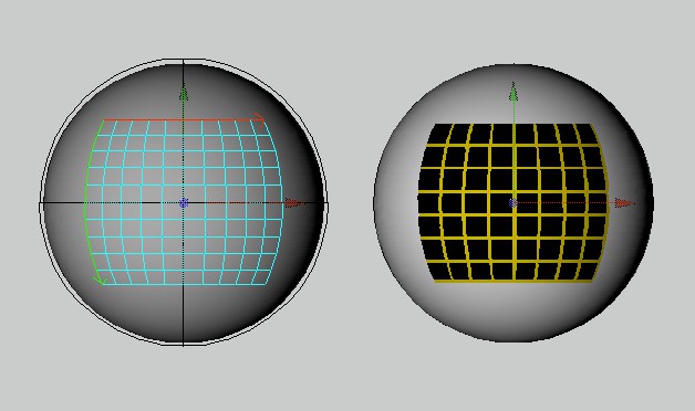
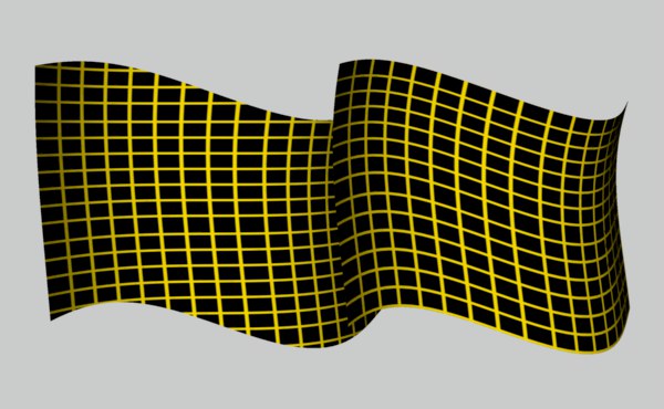 Flat Mapping (left) and UVW Mapping (right).
All of Cinema 4D’s primitive objects and Generator objects have UVW coordinates. If you apply a new texture to these objects, the projection type in the Material tag will default to UVW mapping.
All Polygon objects with UVW coordinates have a UVW tag in the Object Manager.
Primitive objects and Generator objects have internal UVW coordinates and do not have a UVW tag in the Object Manager. You can still use UVW mapping with these objects. If you convert a Primitive object or Generators to a Polygon object, a UVW tag will appear in the Object Manager.
You may be wondering why there are three coordinates (UVW).
What’s the third coordinate for?
Conventional textures have two coordinates, one for the horizontal position (X) and one for the vertical position (Y). In order to make it clear that the coordinates refer to a texture, X is renamed U and Y is renamed V. Two coordinates (U and V) would be sufficient were it not for 3D shaders. These are three dimensional textures and as such they require a third coordinate (W) in order to be fixed to the object.
More than one UVW texture geometry
You can apply more than one UVW texture geometry to an object. Create a new Material tag for the object, then set the projection you require, such as Flat mapping for a label texture. Next, create new UVW coordinates for the active texture by choosing Generate UVW Coordinates from the Object Manager’s Texture menu. The selected Material tag will be set to UVW mapping and will then deform together with the object.
A new UVW tag is added to the existing ones each time you call Generate UVW Coordinates. A Material tag (UVW mapping selected) always uses the UVW map directly to its right in the Object Manager. This allows you to assign different UVW maps to different Material tags. If there is no UVW tag to the right of the Material tag, then the first UVW tag will be used.
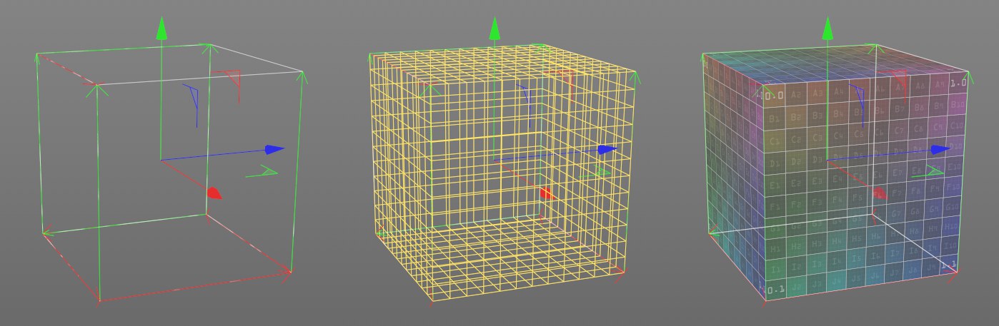
The structure of UVW coordinates
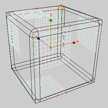
What is the structure of UVW coordinates? Imagine a grid divided into a U direction and a V direction (see Figure 1, below).
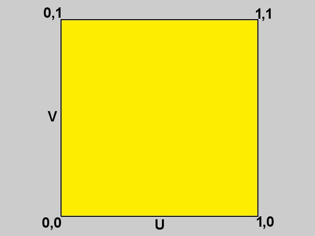 Figure 1.
The UV range starts at 0, 0 and ends at 1, 1. For an upright polygon, 0, 0 describes the bottom left; 0, 1 the top left; 1, 0 the bottom right and 1, 1 the top right. A texture is stretched out between these four coordinates (Figure 2).
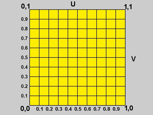 Figure 2.
But where is the W coordinate in this system? Recall that conventional textures are two-dimensional — the W coordinate is created only when needed. Once created, the W coordinate behaves in the same way as the UV coordinates.
Selective UVW Mapping
Cinema 4D has two ways of allocating texture projections to polygon selections (rather than to the whole object as described above). The first method is described below. See above for details on the second method.
Selective UVW mapping allows you to apply a different projection type to several regions of the object using the same texture geometry.
Proceed as follows:
-
Create a sphere and convert it into a polygon object using Make Editable.
-
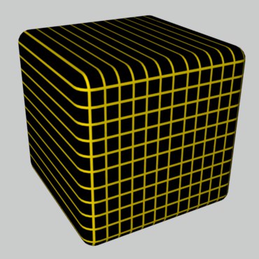
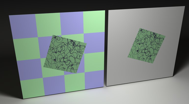
Create a new material with a texture, e.g., the checkerboard shader, and set the projection to Flat.
-
Select the Polygons tool and select several polygons in various locations.
- In the Object Manager’s Tag menu, select the Assign UVW Coordinates command.
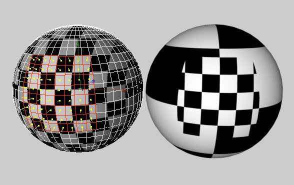
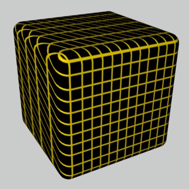
The selected polygons use Flat projection while the unselected polygons continue to use the normal UVW mapping. If you deform the object, the texture remains fixed in the selected region.
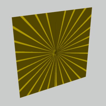
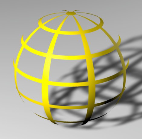
With this projection type, the center of the texture is fixed to the north pole of a sphere and the rest of the texture is stretched over it. The advantage of this mapping type is that the texture meets itself at the south pole only. This avoids a seam running between the poles. Only a circular section of the texture is used, with the center of the circle corresponding to the center of the picture. The remainder of the picture is discarded.
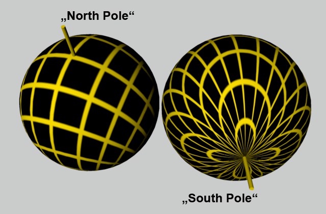 Shrink Wrapping.
 Projection Display Simple, Grid und Solid
.
Use this setting to define how the projection assistance display, which can be adjusted in the Viewport, should be displayed in the Viewport:
- Simple: Only the projection shape will be shown
- Grid: Grids known from Cinema 4D versions prior to R20 will be shown
- Solid: The texture shown on the right will be displayed, which makes it easier to gauge the orientation
A grid will always be displayed if Projection is set to Frontal Mapping.
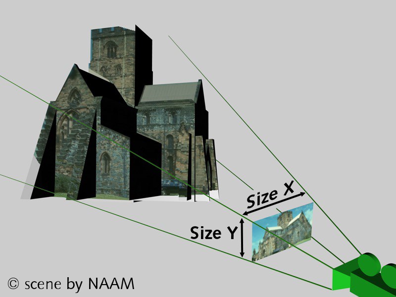
With camera mapping, the texture is projected from the camera onto the object.
Suppose you want to use a photo and have it interact with your models. For example, perhaps you want a 3D figure to walk behind some of the objects in the photo! Camera mapping can help you to pull off these kinds of tricks.
First, load the photo into the Color channel of a new material. Apply the material to the object with camera mapping. For this, you will need a camera for projecting the material onto the object. Switch on this camera for the viewport (viewport: Cameras / Use Camera / Camera XXX).
Now reconstruct (model) any objects in the real picture that the figure (or other objects) will need to pass behind.
For example, if you want a 3D figure to walk behind a crate in the photo, build the crate in 3D (it can be very simple — it is just a screen for the crate texture). Next, project the background texture onto the reconstructed objects (e.g., the crate) using camera mapping. Now your figure can walk behind the crate!.
Example:
Suppose you project a texture onto a tube with Flat mapping. If you move the camera around to look at the other side of the surface, you will still see the texture, but it will be the wrong way round. You can solve this problem by using a decal — a material that is projected on one side of the surface only.
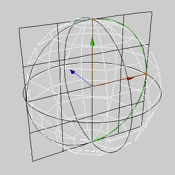
The direction of the surface Normals for each polygon plays a pivotal role in deciding on which side the texture is mapped. Front is in the direction of the surface Normals and Back means in the opposite direction to the surface Normals (see Figure 1).
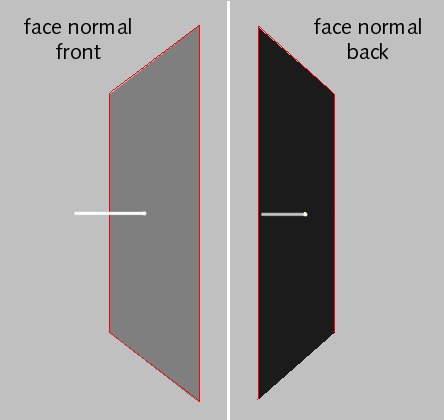 Figure 1.
With Flat projection, a texture is projected from the front through to the back of an object. As a result, the texture is also visible where it is not wanted — in this case, on the front as well as on the back of the tube (Figure 2).
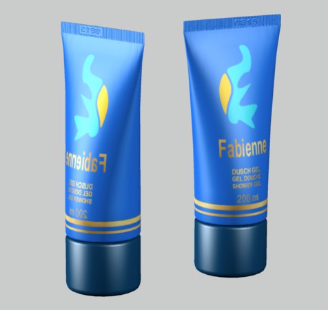 Figure 2. Figure 2.
|
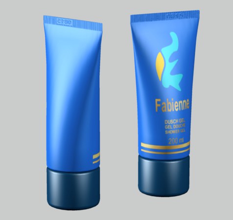 Figure 3. Figure 3.
|
You can avoid such problems with decal mapping. Change Side from Both to Front. Now render the tube again. This time the label is visible on the front side only (Figure 3). If the viewing angle (i.e. the camera angle) and the surface normal form an angle of less than 90° to each other, the polygon is a front polygon. Otherwise, it is a back polygon (Figure 4).
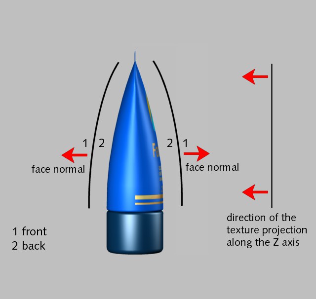 Figure 4.
The only exceptions are for Flat and Spatial mapping. Here there is an additional criterion: the direction of the texture projection’s Z axis. If the texture’s Z axis points in the opposite direction to the surface normal and if the viewing angle and surface normal form an angle of less than 90° to each other, the polygon is a front polygon; otherwise, it is a back polygon.
The texture is projected onto the front and back of each polygon, regardless of which mapping type is selected.
 Both.
Both.
You will see the texture where the surface Normals point towards the camera. Otherwise, the material is invisible.
 Front.
You will see the texture only where the surface Normals point in the opposite direction to the camera. The material is otherwise invisible.
 Back.
Back.
 Texture 1 Front; Texture 2 Back
Attribute Manager settings
Drag the camera that should project the texture into this box.
Defines the aspect ratio of the projected texture. This will be defined automatically when Projection Man is used or when you click on the Calculate button.
The menu provides a list of pre-defined film formats.
If the pixel aspect ratio of the image is not 1:1, enter the ratio here. Note that the ratio will always be set to 1:1 when you click the Calculate button, because pixel aspect ratio information is not stored in bitmaps. The menu provides a list of pre-defined pixel formats.
Clicking on this button sets the Film Aspect and Pixel Aspect (this always 1:1) values to the size of the bitmap. To render the scene the same size as the bitmap, set the Resolution in the render settings (Output tab) to the same size as the bitmap.
The Offset and Length settings define the position and size of the texture in the U and V directions on the texture envelope. For example, if Length U and Length V are both set to 100%, the texture covers the envelope completely
The Tiles values are the number of times the texture fits onto the texture envelope in the U and V directions (Length U and Length V).
Isn’t that the same as changing the length?
Exactly. You can change the length either in terms of tiles (Tiles U, Tiles V) or as a percentage of the texture envelope (Length U, Length V). Either way, changing one will cause the other to change. Note that the texture will only be repeated (tiled) if the Tile option is enabled.
Cinema 4D calculates the size of an individual tile from the current texture size. For example, if you have scaled the texture so that it has a length of 25% in the U direction and 50% in the V direction, the texture fits four times in the U direction (1, 0.25) and twice in the V direction (1, 0.5) on the surface. If you change the Tile U or Tile V settings, the Length settings change automatically. For example, if you change the number to 3, the texture shrinks from 50% to 33.33%.
 Left: 50%; Right: 33%
Repetitions U[0.00..100000.00]
Repetitions V[0.00..100000.00]
If you define the tile size via the Tiles U/V values you can use the Repetition values to define how often tiling should repeat in all directions.
If this option is enabled, the texture picture will be repeated endlessly on the surface.
The effect becomes visible when you scale down the texture or when the texture geometry has not yet been fitted to the object using the Fit To Object command. Otherwise, the texture map fills the texture geometry once.
If this option is disabled, the texture map will not be repeated on the surface. Any materials that are underneath will show through in the parts not covered by the texture tile.
If the Seamless option is enabled, tiles are mirrored to prevent visible seams. However, this sometimes leads to a butterfly effect (similar to an inkblot/Rorschach test) in the pattern, or will result in a pattern similar to a pattern on old-fashioned tapestry.
Prior to Cinema 4D R8.2, the bump was always projected using spherical mapping — even if UVW mapping was defined. Since R8.2, UVW mapping has been used instead provided the Material tag has UVW Mapping selected. This can lead to problems — see the following picture.
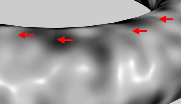 Artifacts with the Noise shader in the Bump shader and Use UVW For Bump enabled.
Artifacts may appear in certain areas in the border area between two neighboring UV polygons, especially when using the Noise shader with a high Delta value. This is caused by the discrepancy between the coordinate systems of the object polygon and the mapped UV polygon. This is a general problem and can only be resolved by increasing the geometry’s resolution.
Alternatively, you can use the old variation that was used automatically before version 8.2. However, keep in mind that this will lead to artifacts at the poles and in addition does not support the realignment of UVWs (especially optimal mapping).
Putting a label on a bottle
- Select the Material tag to display its settings in the Attribute Manager.
- In the Attribute Manager, disable the Tile option.
- Ensure that only one tile is being created in the U and V directions.
Done. The texture probably covers the entire object, but now you can scale it down.
Select the Scale tool, then select the Texture Axis tool. You can drag to reduce the scale of the texture. Next, select the Move tool and place the texture in the desired position on the object’s surface.
The texture is often slightly out of proportion after scaling. Select the Material tag and, in the Attribute Manager, set the Length values as desired. Since the length cannot exceed 100%, you may need to divide both values.
For example, if your texture is 800 x 600 pixels, you might set the lengths as follows:
| Length X | Length Y | Conversion Factor |
| 80 | 60 | / 10 |
| 8 | 6 | / 100 |
| 32 | 24 | / 100 x 4 |
etc.
Texture Layering
Cinema 4D lets you use as many materials and Material tags on an object as you like. Think of a suitcase with travel stickers — there is a base material (i.e. the leather of the suitcase) and many materials on top (i.e. the stickers).
Naturally, you will not be able to see the suitcase leather under the stickers. Also, suppose some of the stickers overlap. A sticker will, naturally, cover any stickers that it is on top of. To see one of the stickers underneath such a sticker, you would have to peel off the top stickers. Or scratch holes in them!
This analogy can be related closely to Cinema 4D’s behavior. Your object has a base material. You have additional materials on top of the base material. In order to see the base material, the overlying materials must be scaled down and not tiled. You can do this by scaling down the texture geometry and at the same time disabling the Tile option. If two materials overlap and you want to see the bottom one, you must make a hole in the top one. You can do this using the alpha channel or clip mapping.
So how does Cinema 4D know which layer a material is on?
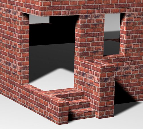
When you apply several materials, each new material is placed on top of the previous one. Thus the order of the Material tags in the Object Manager defines the order of the layers — the right-most Material tag in the Object Manager is the top layer, the left-most is the bottom layer. You can change the layering order simply by swapping the positions of the Material tags using drag & drop.
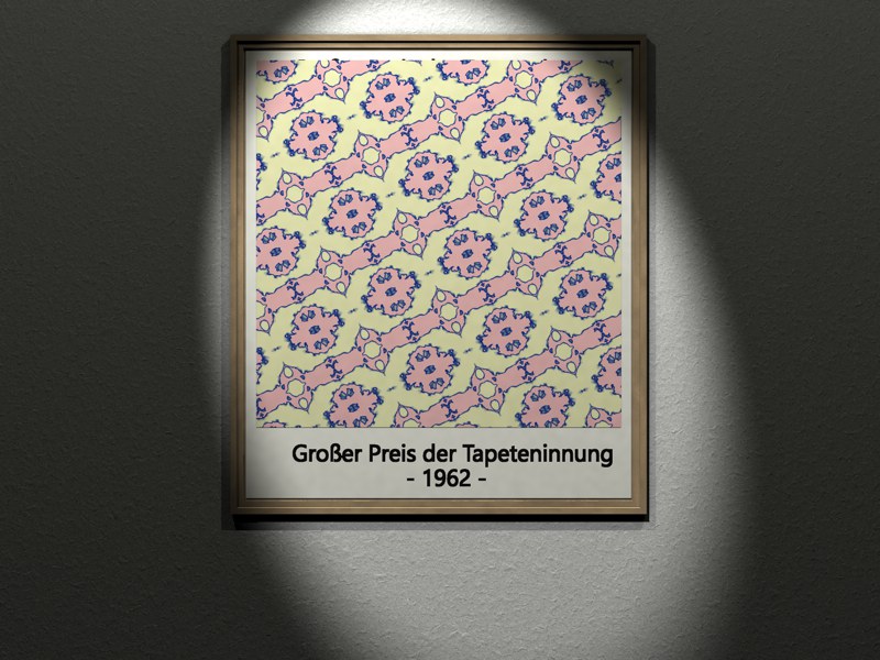
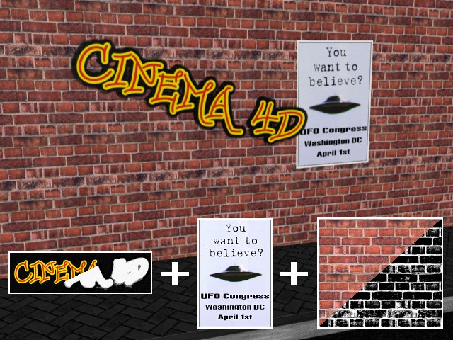 Figure 1.
For the example above, the material T1 was defined as a wall material, T2 as the poster material, which was not tiled but scaled down, and T3 for the graffiti, which was masked out using an Alpha channel.
T1-T2-T3 are layered on top of each other from bottom to top.
Because the top-most material, T3, is masked using an Alpha channel, the underlying materials T2 and T1 are visible. And because the texture geometry of T2 was scaled down and tiling was disabled (very important!) so it does not cover the entire object surface, part of T1 is visible.
The brick material was made using a color channel and a bump channel. The bump channel creates the illusion that the bricks have joints. Now we want to add a second bump map to the wall without changing the texture itself. How can this be done?
The powerful Material tag option that makes this possible is called Mix Textures and can be found on the tag page in the Attribute Manager, for a selected Material tag. By added, we mean that the material properties are added together, hence the term additive materials.
For example, let’s add two textures that are different colors: Red and green; the sum of the colors RGB 100,0,0 (red) and 0,100,0 (green) is 100,100,0 (yellow). If the green color has a brightness of 50%, then only 50% of the color is added. The result in this case would be 100,50,0 (orange).
However, the result cannot exceed the maximum color values. Adding 100,0,0 to 100,100,0 does not produce 200,100,0, but 100,100,0.
Some channels cannot be mixed meaningfully. For example, mixing two materials each with a refractive index of 1 would result in a material with a refractive index of 2, which is probably not what you intended. In such cases, the value of the additive (right-most) material is used (provided that the channel is active).
- You can add together as many textures as you wish.
- Only the following are additive: Color, Transparency, Reflectance, Bump, Displacement, Luminance.
- Only active properties are evaluated.
- An additive material must be to the right of the texture to which it should be added in the Object Manager.
- All materials to the left of the first additive material — up to but not including the next non-additive material — are added.
Returning to the wall example.
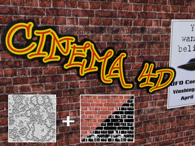 Figure 2.
In the image above you can see the result of additively mixing the relief material T2 with the wall relief material T1.
In the above, you have just learned how to apply and mix multiple materials for a single surface.
Now we want to combine both methods, i.e., several materials will be used on an object, of which several will be added to others.
For our graffiti example, five materials were used. In order of importance from left (T1) to right (T5), whereby T1 (wall), T2 (poster) and T4 (graffiti) are normal materials. T3 (50% relief of T1) and T5 (100% relief of T1) are additive and T4 has an additional Alpha channel.
We will unravel the mystery as viewed in the Object Manager from left to right:
First, T2 is calculated additively with T3, whereby T2 is given an additional relief structure. Because T2 is not tiled, T1 is visible. T4 is calculated additively with T5, whereby T4 is also given an additional relief structure. Since T4 is masked using and Alpha channel, T1 and T2 are visible beneath it.