Node Material Editor
![]()
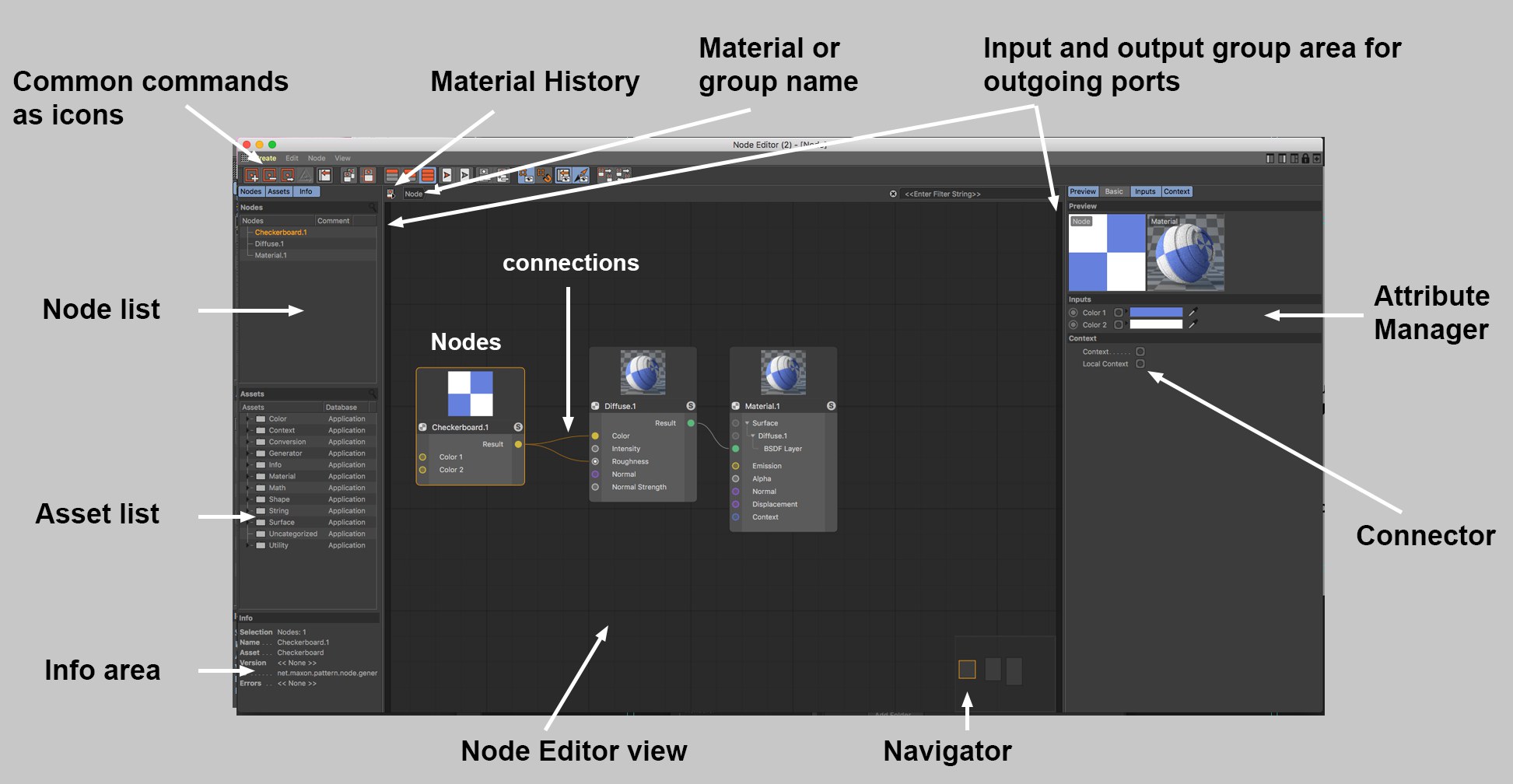
The Node Editor is where everything takes place when creating and editing Material Nodes (in the following referred to as Nodes). Everything you see in the Node Editor has to be linked with a Node Material (please note this tip), i.e., to create and edit Nodes, a Node Material must be selected. The Node Editor always displays the currently selected Node Material.
Please note that Nodes are quite complex and to use them effectively you need to have a higher level of knowledge about how shading and rendering works in general. However, several functions are very simple when a pre-defined material is used such as the Uber Material, which is almost as easy to use as a normal material (and can still be used in conjunction with an image node in various material channels)._
The general flow of data is always from left to right. At the far right, everything must always culminate in a Material Node (no Material Node means no working material; only 1 Material Node per material).
The Node Editor can be opened as follows:
- Right-clicking on a Node Material and clicking on the Node Editor button or double-clicking on the Node Material
- Clicking on a Node Material’s Node Editor button (Basic tab)
As with other Managers; the following hotkeys can be used to navigate in the Node Editor (see also commands in the View menu):
- Move: Press one of the following keys and drag the mouse:
MMB ,1 + LMB ,Alt + MMB or click and drag in the Navigator. If Touchscreen is enabled in the Preferences menu (Input Devices menu), the following will also be enabled: Mouse wheel up/down (move vertically) and - Zoom: Press one of the following buttons and drag the mouse:
Alt + RMB ,2 + LMB , mouse wheel (if Touchscreen is enabled:Ctrl + mouse wheel) - Show all or selected:
H orS .
Nodes can, for example, be created in the following ways.
- Drag a Node from the Asset list into the empty Node Editor (new Node without connections), onto the input port of an existing Node (ports will be connected directly) or onto a connection (only works with fitting Nodes - these will then be added to the connection). Alternatively you can open the Nodes Commander by pressing the c key on your keyboard. For both methods the following applies: if you drag a Node onto an input port and release the mouse button, a small menu will open if multiple output ports are possible where you can select the output port of the first Node to be connected.
- In the Node Editor’s Attribute Manager you will find a connector icon for just about every input type:
 . One click will open the context menu. Selecting Connect Node will display a list of all Nodes. When you select a Node, the Node will be created and simultaneously connected with the input. The same can be done by right-clicking on an input port.
 - Bitmaps should also be mentioned at this point. If you drag a bitmap file from outside of Cinema 4D directly onto the Node Editor view (or even onto ports!), Image Nodes with a correspondingly linked bitmap will be created.
Note that not all output ports can be connected with all input ports. Many file types will be converted automatically but there are limits to this (e.g., a ShadingContext cannot be connected with a BooleDatatype). Cinema 4D will show you if a connection is possible: if you hover over the port to which you want to connect, the potential connection will be either bright (possible) or dark (not possible).
Nodes can be moved at any time by clicking and dragging them. Multiple selections will be moved as a whole. If you move your selection to the edge of the Node Editor view, the view will start to scroll correspondingly.
In order to let data flow from one Node to another they must be connected: For this, Node outputs (right Node side) of one Node can be connected with the inputs of another Node (left Node side). To do so:
- click once on the output port and once on the input port (or vice-versa). This is very practical for Nodes that lie far apart from one another.
- click and drag from the first port to the second and release the mouse button.
- In both cases you can "drop" the connection end onto the middle of the Node: a list with all input and output ports will be displayed from which you can make a selection (if you drop the connection onto an empty area, input/output ports for groups can be drawn out).
The following applies:
- As long as you’re in connecting mode (clicked on the first port to be connected), the mode can be disabled by pressing Esc on your keyboard
- Existing connections can be "re-routed" at the port or the connection itself by
Shift +clicking on other ports (even other Nodes).
Nodes can be selected dragging a rectangle around them (simply click on an empty area of the Node Editor view and drag) or by clicking on them. As always, the
Selected Nodes can be deleted by pressing the

At the very top of the Node Editor you will find the following elements (from left to right):
- Material History: Click on this icon to open a list of the most recently opened Node Materials. Select a material to display it in the Node Editor. For very long histories, it can be useful to type in a series of characters to display only those materials containing those characters.
- Material or Group Name: Next to the History icon you will find the name of the material. If nested groups are included, their hierarchy will be displayed. Clicking on a group higher up in the hierarchy will let you jump to that group. The Edit Asset mode will also be displayed here, which can be exited by closing the opened Node Editor.
- Filter: Enter a series of characters here that affects the Nodes displayed. Nodes whose names contain this series of characters will be displayed more prominently by fading all other Nodes. This can help when looking for specific Nodes among a myriad of Nodes.
The Navigator is located at the bottom right of the Node Editor view - it’s a small depiction of the entire Node constellation and serves for better orientation and quicker navigation, especially for complex Node setups. The light gray triangle shows the visible part of the Node Editor view. You can move this section by clicking and dragging in the view.
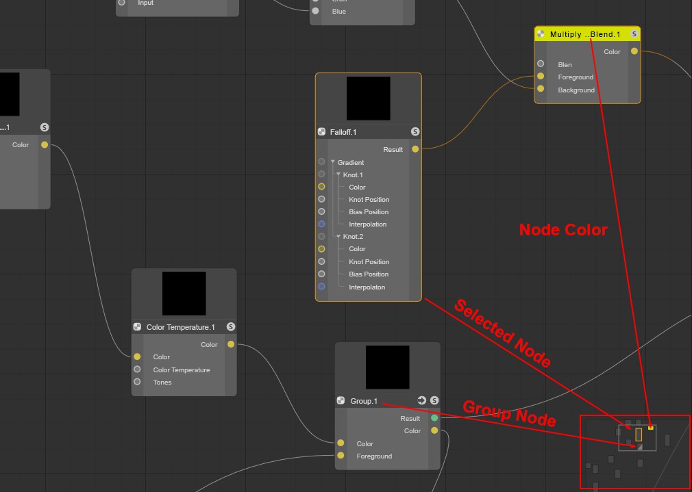
The following Nodes have a special display:
- Colored Nodes (Basic tab) will be displayed with the identical color
- Selected Nodes are also selected
- Group Nodes will be displayed with a diagonal element
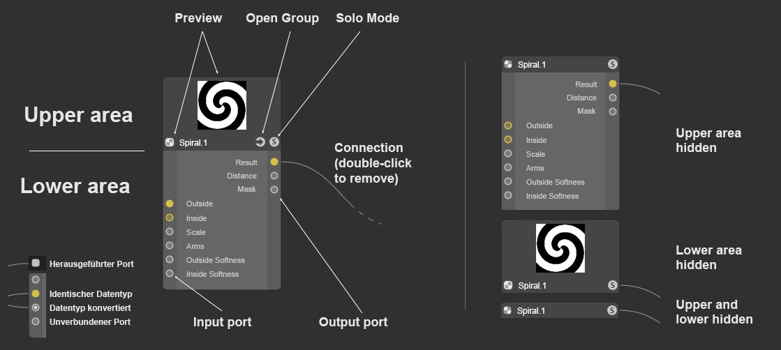
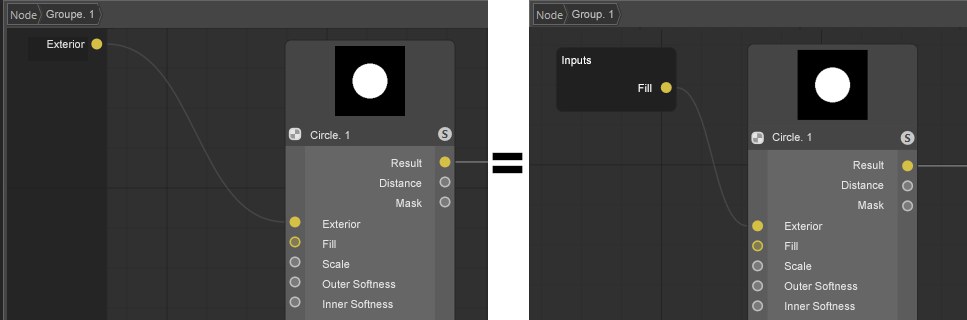
On each side of the Node you will see a dark edge. Ports can be connected with these areas by dropping a new connection into an empty region of the area. This creates an outward connection. This makes little sense for individual Nodes but if you combine different groups with one another, you can use this method to create a port that is shown as a group port (as in the image below). This means that even in a group within a group a specific Node port at the very bottom can be connected from the outside (or as an output to the outside).
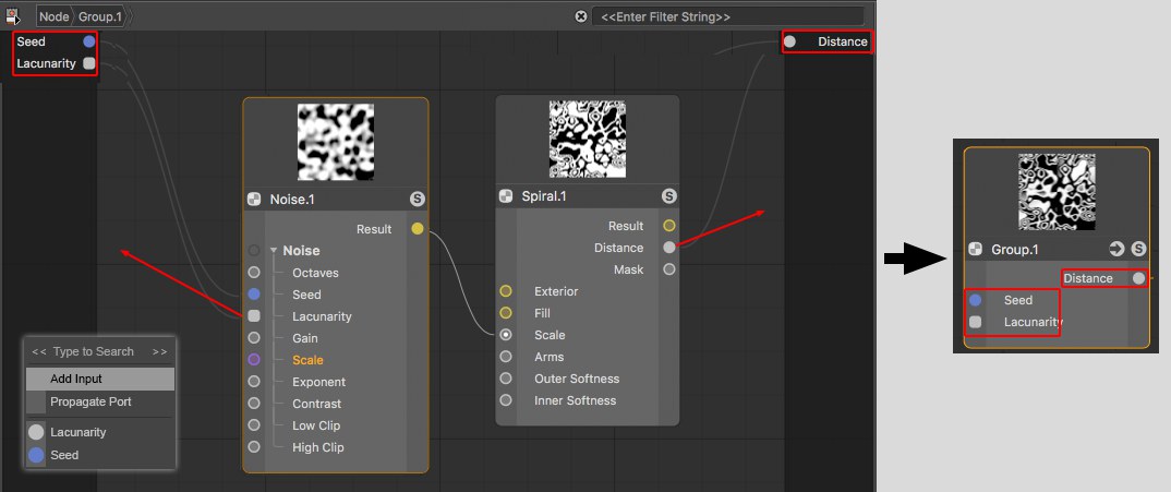 Node ports in groups can be led outside.
When a port is connected with an input or output area, a small menu will open (see image bottom left) with the following options:
- Filters with which you can filter out the elements you don’t need by entering a string of characters
- Add Input, round port: Here, the connection can be deleted without deleting the input. An input can be re-connected from the inside.
- Propagate Port, square port: If you remove the connection here, the port will also be deleted. Ports also pass on their properties to the outside, which, however, is currently barely used.
- Existing ports/inputs/outputs: If the port to be connected should be connected with an existing input or output, this can be done by making a selection from the list.
Parts of the described functionality (creating inputs) can also be done via the port context menu commands.
Note also the Input and Output Nodes, which do the same thing but can offer a better overview.
General information about Nodes
 A Node setup and display example (it’s also possible to only display connected ports).
The core component of the Material Node System is - logically - the Node. A Node has inputs into which data from other Nodes is entered, which is then processed by the Node and the result is passed to its outputs. Inputs and outputs have ports through which the connection to other Nodes can be made. Basically, an input port can only have a single connection and output can have any number of connections.
Nodes can be grabbed on the left or right edge and made wider or narrower.
A typical Node has an upper area and a lower area:
The upper area contains the Node preview. If the settings of the connected input Nodes change, the preview will change accordingly. You can show or hide the preview using the small icon at the left of the Node name (a command can also be used - see above).
Below the preview are the Node name on the left, which is also displayed in the Basic tab. Double-click on the name to rename the Node (which can also be done with port names - but cannot be undone there …). Note that differences in names of the Nodes/setting names can occur in the documentation.
At the right of the Node name is an arrow icon if the Node is a Node Group. Click on the arrow to show the group’s contents in the Node Editor view. The Solo icon is to the right of the arrow (see Solo).
The background color of the upper area can be changed using the Custom Node Color option in the Basic tab.
The lower area contains the input ports on the left with their respective names - these can be re-named by double-clicking on them - and the output ports on the right with their respective names. Ports can be hidden, and their order can be changed by moving them. Note that not all input ports will necessarily be listed in the Node itself. These can be displayed using the context menu.
Certain Nodes (such as the Layer Node, for example) even have drop-down port groups for each layer.
Depending on the data type being processed, ports will be assigned a certain color (see next data types).
Ports can be selected (using the
Inputs and outputs are colored accordingly. Fitting data types for input and outputs will be displayed using colors. The most important types are:
- Dark gray: Represents a container consisting of various data types, as would be the case when transmitting complex settings for shading for a given material.
- Light gray: Represents numeric values. This can be whole numbers (integers), percentages or a number with a comma value (float).
- Yellow: Used for color values (RGB vectors) or textures
- Blue: Used for simple options (Boole data type), i.e., for simply enabling or disabling a function or, for example, for a material. UV coordinates and texture projections can also be transferred and the forwarding of complex data types such as matrices also run through blue ports.
- Violet: These are ports that work with vectors, for example, in conjunction with Normals and for the displacement of a material or if an object’s position should be ascertained.
- Green: Reserved for BSDF layers, which can be used to define physical shading and reflectance information.
As in XPresso, atypical input and outputs can be connected with one another. As a rule, a constructive conversion of the data types will take place. For example, a texture can also be connected to an input for a float comma value. The texture’s RGB values will then automatically be converted to brightness values. Using this method, color textures can also be used to, for example, control the Roughness of a BSDF layer. This type of conversion of data types is denoted at the receiving Material Node by an additional point at the respective input.
If you right-click on a Node/port, a comprehensive context menu will open, which contains commands mostly from the Node Editor menu. These are described here, except for the following:
Enter a series of characters here to filter out elements you don’t need (only commands, Nodes, etc. that contain these characters will be displayed).
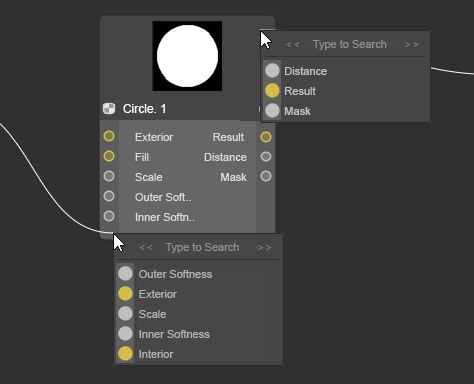
Not all inputs listed in the Attribute Manager have to be displayed by the Node as a port. Sometimes only the most important are shown. Use the Add Port command to show all hidden ports. If one is selected, it will be displayed again (if All is selected, all input ports will be made visible).
This menu point is not available if all input ports are displayed.
Normally, all outputs are displayed. If not, (e.g., if Remove Unused Ports was applied) these can be displayed by selecting one of the output ports from the list.
A list will be displayed from which a Node to which you can link can be selected. If multiple output ports come into question per Node, click on the small black arrow and the output ports that can be selected will be displayed. In addition to the complete Asset list, the first entries will be existing Nodes where Nodes are listed that are contained in the current Node Editor view. There is also the Add Group Input option with which a port can be drawn from a group (see also Input and Output Group Areas).
Note that this list is created dynamically, and only fitting Nodes will be suggested.
For the current, connected input port, the "feeding" Node will be replaced by one from the list. Note that the complete Node chain will be deleted at the Node to be deleted. This only applies to the Nodes being fed: Nodes that are connected to other output ports remain unaffected.
All loaded textures are listed here. Select a texture from the list to feed it into the input port.
Selecting this option will open a context window from which you can select a bitmap or video, which will then be fed to the input port using an Image Node.
Several Nodes such as the Layer Node or the Gradient make this command available. With it you can delete elements such as Layers or Knots.
Selecting this command will hide the selected ports. This only works with ports that are not connected. The hidden port will then appear in the previously described list under Add Input (and can be made visible there).
Note also the ![]() Show All Ports
Show All Ports
Most settings have a default value, which is defined when the Node is created. Using this command, modified values will be reset to their default values. This only affects Nodes that are not connected.
Calling up this command (only of use when the Node Editor view shows a group’s contents) creates a connection to the outside or to the parent hierarchy. See also Input and Output Group Areas.
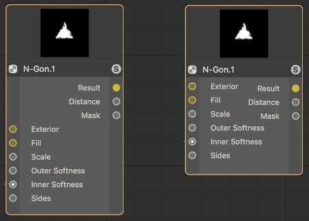
A Solo functionality can be enabled for Nodes. If this Node has multiple outputs, one of them must be defined as a Solo Port, which is what this option does.
In the upper area of a Node you will find the Node’s preview. If a Node has multiple outputs, this option can be used to define which output should be displayed in the preview.
Proceed as follows to connect a Node port with another port:
Connections can also be selected, whereby you can almost always do so in conjunction with the
If ports are already connected, this command can be called up. It places a Converter Node in the connection, i.e., its input and output are already properly connected.
Deletes selected connections.
Muted connections will be displayed with a dashed line. Values will not be accepted from the previously connected Node but from the Attribute Manager instead. This lets you temporarily disable connections for test purposes, for example.

At the top right of the Node Editor you will find the following 5 icons, from left to right:
- Left column: Use this icon to display or hide the left column, which contains the Node and Asset list as well as the Info area.
- Right column: Use this icon to display or hide the right column, which contains the Attribute Manager.
- 2-column view: Use this icon to display or hide the 2-column view. All managers (Node and Asset lists, Info area and Attribute Manager), which would otherwise be visible in the 3-column view will all be placed at the right.
- Lock Node view: Normally, the Node view will show the Node Material currently selected in the Material Manager. If the view should not change, this option can be enabled to prevent this from happening.
- New Node Manager: This will open a new Node Editor. This can, for example, be helpful if you have a Node network made up of hundreds of Nodes and want to work in several areas simultaneously. Or you want to make the Nodes of two Node Materials visible at the same time (see also previous icon).
The Attribute Manager is available in the Node Editor in a somewhat reduced form. The Attribute Manager shows the properties of selected Nodes or Node Materials. Most functions work as described under Attribute-Manager. Below only the major differences are described.
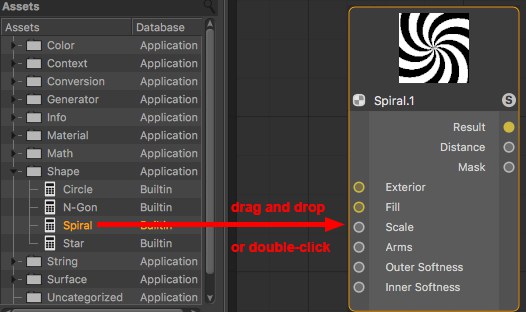
Create a Spiral Node, for example (Asset list: Shape/ Spiral):
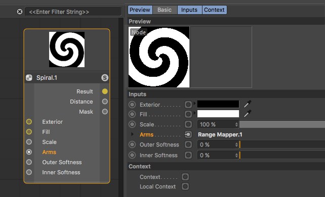
As you can see, all input ports are also listed in the Attribute Manager. The Attribute Manager even offers more settings than the Node has input or outputs. The Attribute Manager contains all settings. The Node generally only has one selection as an input or output - Preview and Basic tab settings are not included.
Output ports are not listed here since their values result from calculations within the Node, which you can only modify indirectly by changing input values.
The most major change compared to the previous Attribute Manager are the linked fields that have been replaced by Connectors. Node inputs can either be fed with values by simply entering values for given settings or - and this is new - by connecting Node inputs with node outputs of other Nodes, i.e., make a connection (which is what Nodes are all about).
Click on the icon at the right of the setting name (the "connector") and select a Node from the Connect Node list to connect with the input that you select (you can, of course, simply connect ports in the Node Editor view). The selected Node will be created and linked:
Bitmaps can at any time be dragged from outside of Cinema 4D onto a complete parameter line *incl. parameter name, connecting icon and GUI element) to link a given setting using an Image Node.
As soon as a parameter is connected with another Node, the following applies:
- A small arrow will appear instead of the animation icon. Click on this arrow to display the settings of the docked Node.
- The setting can no longer animate these using the usual animation icon - this will then be displayed (of course you can animate the setting of the connected Node as usual). A setting cannot be controlled simultaneously by the Timeline and another Node.
The animation icon displays dependencies between animation and XPressions, while the connector icon symbolizes dependencies between shading and renderer.
The connector icon can have one of the following 3 states:
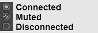
- Connected: The values flow from the linked Node to the Node input. On the right next to the Connector, the linked Node’s name will be displayed. You can click on this name to select the corresponding Node and display its settings.
- Muted: A connection to another Node exists, whose values will, however, not be assumed (instead, the values defined in the Attribute Manager will be used).
- Disconnected: The values defined in the Attribute Manager will be used.
Clicking on a connector icon will make the following commands available, from which most should already be familiar from the port context menu. The connector icon makes a similar functionality available, which makes it possible to access a port in the Node Editor per right-click.
In the following, only the Connector’s commands are described.
This command can, for example, be found in the Layer Node. The selected Node will be linked with a new layer.
Copies the connected output port to the cache.
The cached output port can then be linked with a different input port. This way, multiple inputs can be connected with the same output port.
This command connects the output port in the cache with the input on which you click. Contrary to the previously described command, a duplicate of the entire feeding Node is created.
Removes the connection from the input port.
The connection is maintained but no data will be passed. Instead, the value defined in the Attribute Manager will be used for the input. Call up the command again to allow data to be passed again.
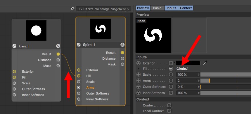
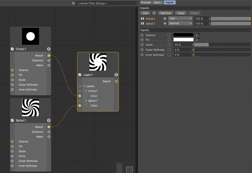
Several Nodes such as the Layer Node or Grading Node offer this mode. Enable this mode, for example, to display the layer settings as animatable or adjustable settings. In addition, the input settings of the feeding Node can be displayed by activating one of the layers. In the following example, the inputs would be those of the Circle Node.
For the Grading Node (click on a Knot and on one of the subordinate connector icon to call up the command), the settings of all Knots will be displayed. Call up this command again to return to the previous mode.
Several Nodes such as the Distance or Value Nodes can assume the units and the parameter displays of subsequently connected Nodes for their input ports.
At the top left you will find the Node list where all Nodes and Groups in the current group hierarchy are displayed. Here you can:
- Select Nodes (by clicking or right-clicking on them;
Shift andCtrl/Cmd keys can be used as usual) - Delete selected Nodes
- Rename Nodes by double-clicking on them
- Duplicate Nodes (use the
Ctrl/Cmd key to move them to a new location in the list)
The list order has no influence or further meaning.
Klick on the search icon at the top right to display a text filter. Enter a series of characters to hide all nodes that do not contain these characters in their names.
In the Asset list you will find all Nodes included in Cinema 4D as well as custom Assets (the Node Commander makes the same functionality available and can be called up from within the Node Editor using the
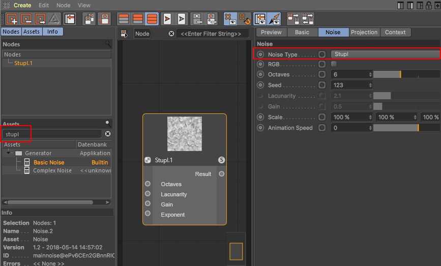
Example: The Color Grading Node internally contains the keywords "correction, tones, HSL, HSV", etc. If you enter these characters, this Node will be displayed. Another example would be noise names (e.g., Luka, Stupl, etc.), with which Noise Nodes can be located. A special function is also used here: if you create an Asset containing ,Stupl’, it will be set to the Noise Type Stupl. This also works, for example, with the Mix Node (type ,multiply’, for example).
For several Nodes such as the Mix Node, this can even be taken further. For example, if you filter for ,multiply background’ (several characters are combined with a logic AND) and create a Mix Node, both the Mix Mode and Use Alpha selection menus will be set accordingly.
The Node name itself will, of course, also be found (and will be given a higher priority than the keywords).
Multiple selections can be made in the Asset list (use
An Asset can be created via double-click on the filtered list. Alternatively, you can also use the cursor keys to navigate and create the selected Asset via
Otherwise you can open and close a selected Group using the cursor keys
In addition to the Assets themselves, the Asset list has a Database column, which shows where the Asset is saved, For example, if Builtin is displayed, you know that this is a core Asset from a Base Node created by , which cannot be "looked into". Other Assets are core Assets combined in groups (and can be "looked into"). These are, for example, databases with names such as Utilities or Materials.
For Preferences and other databases you name yourself or imported Assets, these are not Assets created by that are saved in the Preferences menu (in a folder named userrepository or anywhere else.
Information about creating and managing Assets can be found under Assets (here, all context menu commands are described).
At the bottom left you will find the Info area in which you will find information pertaining to Nodes, connections and ports.
For Nodes:
- Selection: The number and type of selected elements
- Name: The Node name as it is defined in the Basic tab
- Asset: The non-modifiable Asset name as it is defined internally. Why do the Asset and Name infos differ? You can change the Name at any time and may then have difficulties recognizing what the original Node was.
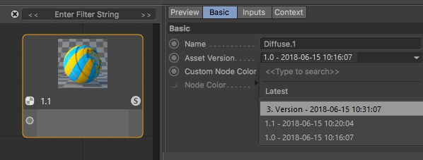
- Version: When you create Assets, a version number can be defined, which is then displayed here, including date and time. This way you always know which Asset version you are currently using.
- ID: A unique ID, which has no additional informational value for you.
- Errors: Here all errors will be displayed (e.g., if an automatic conversion of a data type failed)
Additional information for connections:
- Selection: The number of selected connections
- Port Type: The data type that the port expects as input or itself puts out
- Connected Type: The data type that flows through the connection
Additional information for ports:
- Port Value: If a port has no connection, the value defined in the Attribute Manager will be displayed
Creates an empty group for the current Node Material.
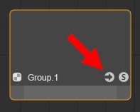
Click on the arrow icon to open the group.
Groups are summary, parent Nodes that contain a network of Nodes (and/ or groups as well) The ports of Nodes in these groups can also be propagated outwards in order to feed values from Nodes outside of the group or to access values of Nodes within the group.
Groups can be converted to Assets and passed on.
You can also select multiple Nodes and group them using the following command.
Input and output nodes have the same functionality as the Input and Output Group Area: they lead ports outwards so that these inputs and outputs are directly ,accessible’ in the parent group. Any number of input or output nodes can be created. The advantage compared to the Input and Output Group Area: dozens of connections don’t always offer the best overview, which can make placing input or output nodes near the connected node port difficult. You will not have extremely long connections that block your view or are difficult to navigate through.
Right-click on an input or output Node and select
Ports in the Input and Output Group Area can be dragged by their name into the node view to convert them to input or output nodes.

Multiple node ports can be connected with the same input node port; contrary to the output node where this will not work.
Groups selected Nodes (see also previous command).
Ungroups grouped Nodes and deletes the Group Node. Connections are maintained - as well as outwardly, if possible.
To dissolve Assets they must be converted in groups first.
Creates new input/ output ports. This is only useful for Nodes within groups (see also Input and Output Group Area).
With this command you can create parameter input ports for all selected ports. See Input and Output Group Area for differences between input and output ports and propagated ports.
Details about Assets can be found under Assets.
Assets are most often created from Group Nodes (an example process is described here).
As soon as this command (or several - they will be processed in the order they are called up) is called up for a selected Node, a dialog window will open:
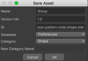
Define a name for the Asset. This Asset will appear with this name in the Asset list. This name will also appear in the Info area if you use it in the Node Editor view as an instance (i.e., you drag it from the Asset list into the Node Editor view). Even if you rename the Node, this name will remain unchanged.
Assets can have several versions (versioning). Imagine you create an Asset, build a scene with it and save the scene. You then edit the Asset (right-click on the Asset in the Asset list: Edit Asset) by, for example., changing a color or adding Nodes. If you now save the Asset (Save New Version) you can use the Version Tag to define a version (e.g., 1.1 or Version 2, etc.). The Asset will then contain both the original and the new version.
If you now load the originally saved scene or use the Asset anew, the newest Asset version will be used by default. You can, however, switch between versions in the Asset instance (i.e., the Group Node) at any time:
You can also imagine versioning as follows: Assuming you saved a primitive cube in Cinema 4D R15. A Fillet setting was added in R18. If you load the R15 scene into R18 you often had a compatibility mode that lets you load and older version. If the option is enabled, the cube is loaded without fillets, if disabled, with fillets. Sometimes the cube would be loaded without any prompt regarding its older state. If versioning were applied to primitives, you would be able to switch back-and-forth between versions.
MAXN can update the nodes it supplies in the application via the Online Updater. This is done in a manner that ensure that older scenes remain functional.
What you define here in the Version Tag will subsequently appear in the Asset instance as the Asset version name.
This is a unique ID (you don’t have to enter anything) is assigned with which an Asset can be clearly identified by the application. This ID - supplemented by a random set of characters - is then displayed in the Info area of the Node Editor when the respective Node is selected.
Assets can be saved in different databases.
Most often, the following will be offered:
- Preferences: Assets will be saved in the default directory userrepository
- Scene: An Asset copy will be copied in the scene file (this also happens if the scene is saved using the Save Project Including Assets option).
- + Databases that are linked in the Preferences menu under Files/ Paths/ Databases. Note that Assets linked as ZIP files in databases cannot be saved in these)
This menu is dynamic and will display all corresponding locations.
If you take a look at the Asset list you will see numerous Assets in the alphabetically arranged categories. You can add categories at any time (these are themselves Assets by the way).
The Asset to be saved will be placed in the selected category. If you select New Category, a new category can be created using the New Category Name option. Custom Assets can be dragged and dropped to other categories.
Clicking on OK will save the Asset and add it to the Asset list and will make it visible in the Node Commander where it can be used.
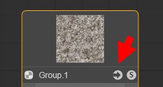
Asset Nodes, which are mostly created from groups, can be converted back to Groups using this command. The arrow icon will then be displayed again.
Opens the group.
When editing existing Assets, modifications made should be saved using this command. A dialog window will open that you should be familiar with from the Save Asset command (see above). Since the old Asset state is also saved, versioning will be implemented.
When editing existing Assets, a new Asset can be saved without the aforementioned versioning. A dialog window will open that you should be familiar with from the Save Asset command (see above).
If you open an Asset using the Edit Asset command, you will be switched to Edit Asset mode. Calling up this command will exit this mode. You may be prompted to confirm or discard the changes made to the Asset. Changes made to Assets must be confirmed (e.g., via Save New Version).
These are the usual commands with which you can delete changes made in the Attribute Manager or undo/ redo functions. Contrary to the XPresso editor, moving or expanding Nodes is not included for these functions.
Here you can copy selected Nodes to the cache (for Cut, the Nodes will also be deleted) and Pasted in the Node Editor. Existing connections between the selected nodes will also be copied.
Selected Nodes will be duplicated, (including all existing connections).
Alternatively you can Cmd/Ctrl + click on selected nodes and move them. This will duplicate them automatically.
Selected Nodes will be deleted. Pressing the
Selects or deselects all Nodes.
Selects all Nodes connected to the selected Node. This makes it easy to select a series of connected Nodes.
The Node Commander offers functionality similar to the links in the Node Editor’s Asset list. You simply have to press the
In addition to the functions described in the Asset list, the Node Commander offers the following functions:
- Pressing the
Esc key or clicking outside of the Commander will close the window (the order of the characters in the filter will be maintained) - Pressing the
TAB key switches from the list to the filter field - Pressing
Shift +TAB switches from filter field to list
Opens the Material Editor for the material currently displayed in the Node Editor. In principle, the Material Editor has the same settings as the Attribute Manager for a selected material.
This command selects the corresponding Node Material in the Material Manager for the active Node Editor, whose material settings will then be displayed in the Attribute Manager.
These commands can be used to show or hide the Node’s preview (in the upper area of each Node). The application’s Preferences menu has a Material tab in which a default setting defines if the preview for new Node creation should be visible or not. What good does it do to hide the preview since it actually offers valuable information. Well, for very extensive Node networks it can be very computationally intensive to update all previews when changes are made. In such cases it can be useful to hide the preview.
 Left disabled, right enabled Horizontal Ports option.
Use this option to define how the input and output ports should be arranged in the node:
- Option disabled: Input and output ports will not lie evenly arranged.
- Option enabled: Input and output ports will lie evenly arranged.
Hide all Ports hides the port area for all selected Nodes (double-clicking on a Node will do the same). The connections are maintained. This is a purely optical effect, for example, to get a better overview of your setup. Double-clicking again or calling up the Show all Ports command will reverse the effect.
Selected ports can also be defined as hidden via the context menu. The Show all Ports command will then not make these visible again. You will have to define the respective port as being visible via the Add Input command.
Only the ports with connections will be shown for the selected Node. All others will be hidden. This can be undone using the Show all Ports command.
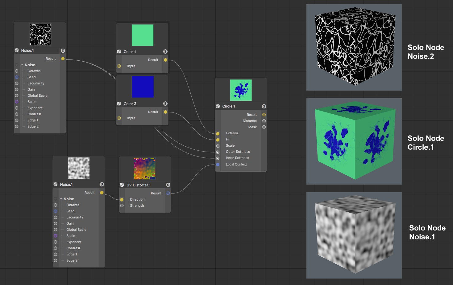 Different Nodes defined as Solo Nodes, rendered texture on a cube.
The enabled Solo Node mode omits all other Nodes. In the Node Editor view and for rendering, only the Nodes fed into the Solo Node and the Solo Node itself will be evaluated and displayed. This is, for example, very useful if your Node preview is too small because you can display or render the effect of individual Nodes at any scale.
Use this command for a selected Node (possibly with a selected output port: see also Solo port) or simply click on the Node’s S icon.
Logically, only a single Node can be a Solo Node. To exit the Solo Node function, call up the Set Solo Node / Port command or simply click again on the S icon.
Node Materials can be made up of very complex networks consisting of hundreds of Nodes. If you want to make minor changes to a material without diving too deeply into the Node Editor, one Node - a single Node per Node Material - can be defined as a Start Node. This Node’s inputs (and only this Node’s inputs) will be displayed in the Attribute Manager or the Material Editor’s Input tab when the material is selected.
If, on the other hand, you only want to display a few ports and you’re working with groups, propagate the respective ports from the group and define the Group Node as a Start Node.
Start Nodes will be marked with a green frame if unselected and with a bright yellow frame if selected.
In the following example, only the Spiral Node’s Arms setting should be displayed as an externally controlled setting. Proceed as follows:
- Place all Nodes in a group by selecting them and selecting Group Node from the context menu. Open the group (click on the Group Node’s arrow icon).
- Right-click on the Spiral Node’s Arms port and select Propagate Port from the context menu.
- Exit the group by clicking on Node in the Material or Group Name
- Select the Group Node and select Set as Start Node (Node menu)
As soon as you select the Node Material, only the Arm setting will be displayed (image bottom right).
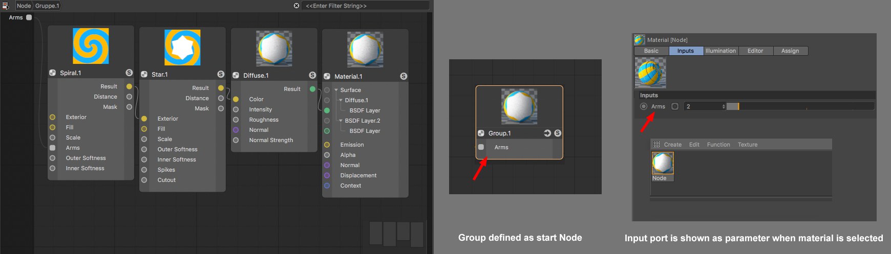
If you now click on the Group Node to select it and select Convert to Asset , the Asset will be created.
The Clear Start Node command removes the Start Node state.
Opens the Material Editor for the material currently displayed in the Node Editor. In principle, the Material Editor has the same settings as the Attribute Manager for a selected material.
This command selects the corresponding Node Material in the Material Manager for the active Node Editor, whose material settings will then be displayed in the Attribute Manager.
Unused Nodes are Nodes without connections (filled groups and materials are not included). They therefore serve no purpose and can be deleted using this command.
This command only works if at least one connection exists for each input or output port group: for the selected Nodes, all ports without a connection will be hidden (these can be unhidden using the Add Input or Add Output commands). Otherwise the ports will remain visible.
If Nodes lie outside of the Node Editor view, these can be shown simultaneously using this command. The view will be scaled accordingly to ensure that all Nodes are displayed.
Shows all Nodes in the Node Editor view. The view will be scaled accordingly.
Selected Nodes will be displayed at the center of the view without changing the zoom factor. For multiple selections, the center of the selected Nodes will be placed at the view’s center.
All Nodes will be placed at the center of the view without changing the zoom factor.
Enlarges or reduces the Node Editor view. Using the
If you have a Node network made up of 376 Nodes, for example, you won’t see much detail in the Node Editor view. This command sets the zoom to a quite legible 100%.
Hides or shows the grid in the Node Editor view. Grid snapping works independently of this display.
Enables or disabled grid snapping. If enabled, Node edges will snap to the grid lines.
Enable this option to display group (Wires). See also Input and Output Group Areas. These are often outgoing connections that clutter the view because they are so numerous - which is why you can also disable this option. This command also applies to the connections with the input and output nodes.
Connections are curved by default. Enable this option to make the connections appear linearly.
Shows or hides the Navigator.
If a Node produces errors or is fed with invalid data types, a red frame will appear here (then look for error messages in the Node list or the Info area that can provide more information). This frame can be hidden if the Show Errors option is disabled.
When working with groups you often have to delve into these, i.e., the Node Editor shows the contents of a given group. Call up this command if you want to move up a level, i.e., out of this group. Alternatively, you can click on a layer to which you want to jump next to the material or group name.
Selected or all Nodes will be arranged so they are visible in the current view - compact, arranged in order and positioned horizontally/ vertically:
 Before and after the Layout All command is called up.
With this command you can create parameter input ports for all selected ports. See Input and Output Group Area for differences between input and output ports and propagated ports.
Details about Assets can be found under Assets.
Similar to Edit Asset, only that a selected asset instance must lie in the node view.
Assets are most often created from Group Nodes (an example process is described here).
As soon as this command is called up for a selected Node, a dialog window will open:
Define a name for the Asset. This Asset will appear with this name in the Asset list. This name will also appear in the Info area if you use it in the Node Editor view as an instance (i.e., you drag it from the Asset list into the Node Editor view). Even if you rename the Node, this name will remain unchanged.
Assets can have several versions (versioning). Imagine you create an Asset, build a scene with it and save the scene. You then edit the Asset (right-click on the Asset in the Asset list: Edit Asset) by, for example., changing a color or adding Nodes. If you now save the Asset (Save New Version) you can use the Version Tag to define a version (e.g., 1.1 or Version 2, etc.). The Asset will then contain both the original and the new version.
If you now load the originally saved scene or use the Asset anew, the newest Asset version will be used by default. You can, however, switch between versions in the Asset instance (i.e., the Group Node) at any time:
You can also imagine versioning as follows: Assuming you saved a primitive cube in Cinema 4D R15. A Fillet setting was added in R18. If you load the R15 scene into R18 you often had a compatibility mode that lets you load and older version. If the option is enabled, the cube is loaded without fillets, if disabled, with fillets. Sometimes the cube would be loaded without any prompt regarding its older state. If versioning were applied to primitives, you would be able to switch back-and-forth between versions.
MAXN can update the nodes it supplies in the application via the Online Updater. This is done in a manner that ensure that older scenes remain functional.
What you define here in the Version Tag will subsequently appear in the Asset instance as the Asset version name.
This is a unique ID (you don’t have to enter anything) is assigned with which an Asset can be clearly identified by the application. This ID - supplemented by a random set of characters - is then displayed in the Info area of the Node Editor when the respective Node is selected.
Assets can be saved in different databases.
Most often, the following will be offered:
- Preferences: Assets will be saved in the default directory userrepository
- Scene: An Asset copy will be copied in the scene file (this also happens if the scene is saved using the Save Project Including Assets option).
- + Databases that are linked in the Preferences menu under Files/ Paths/ Databases. Note that Assets linked as ZIP files in databases cannot be saved in these)
This menu is dynamic and will display all corresponding locations.
If you take a look at the Asset list you will see numerous Assets in the alphabetically arranged categories. You can add categories at any time (these are themselves Assets by the way).
The Asset to be saved will be placed in the selected category. Custom Assets can be dragged and dropped to other categories.
Clicking on OK will save the Asset and add it to the Asset list and will make it visible in the Node Commander where it can be used.
Asset Nodes, which are mostly created from groups, can be converted back to Groups using this command. The arrow icon will then be displayed again.
Opens the group.
If an asset is encrypted, this command will be grayed out.
When editing existing Assets, modifications made should be saved using this command. A dialog window will open that you should be familiar with from the Save Asset command (see above). Since the old Asset state is also saved, versioning will be implemented.
When editing existing Assets, a new Asset can be saved without the aforementioned versioning. A dialog window will open that you should be familiar with from the Save Asset command (see above).
The following material was created using Nodes only. Not bitmap or texture was used!
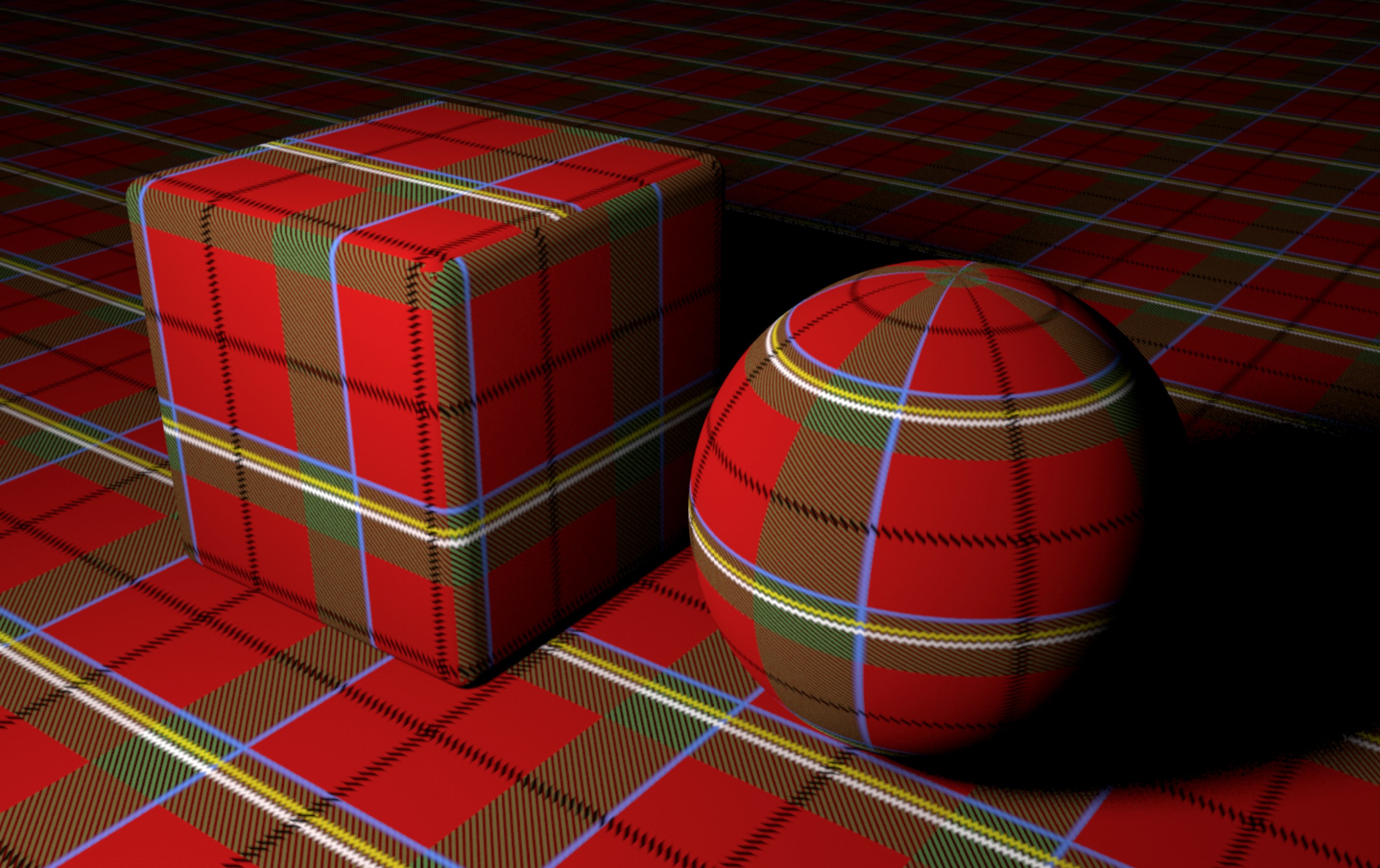
Load the following scene:

Here you can get an idea of what is possible using Nodes. Right-click on the material and select Node Editor to see what the Node setup looks like. Note the Plaid Group Node in which additional Node networks are nested.