Object Properties
You can select from two modes with which a MoSpline can be generated:
Spline segments will fan out from the Spline’s origin. Numerous settings are available for bending and arranging these segments. These settings are described in detail in the "Simple" tab description.
Turns an existing Spline into a MoSpline. These settings are described in detail in the Spline tab description.
In Turtle mode, plant-like structures can be made to grow. This is done using an integrated L-System.
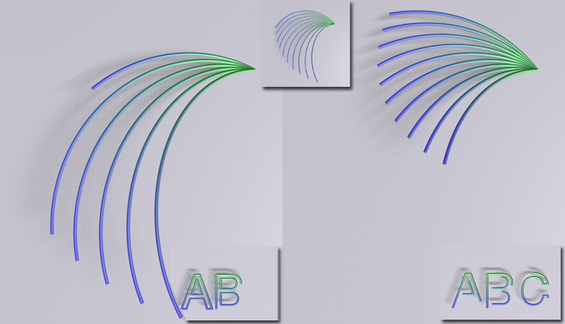 Animated End parameter: left in
 This mode defines how the MoSpline will grow with regard to the Start, End and Offset parameters:
The MoSpline will work its way successively along each Spline segment.
The MoSpline will grow or move along each segment concomitantly.
By default, these values are set to 0% and 100%, respectively, which ensures the entire MoSpline is shown and rendered. A MoSpline can be made to grow by modifying these values accordingly. If the Extend Start and/or Extend End options are enabled, these values can be set to less than 0% or greater than 100%, respectively.
When in
The Offset value is used to move the MoSpline segment, as defined by the Start and End values, along the entire length of the Spline and beyond (if the Extend Start and/or Extend End options are enabled). A positive value will move the segment forwards, a negative value will move it backwards.
The following parameters, which are made visible by clicking on the small arrow next to the Extend Start and Extend End options, respectively, influence each other reciprocally.
Their values can also be set to less than 0% or greater than 100%.
The Extend parameters’ settings define how the MoSpline will behave when it is pushed beyond its limits, as defined by the Offset 0%, Start 0% and End 100% values.
If the respective option is disabled, the MoSpline will simply end according to the values defined.
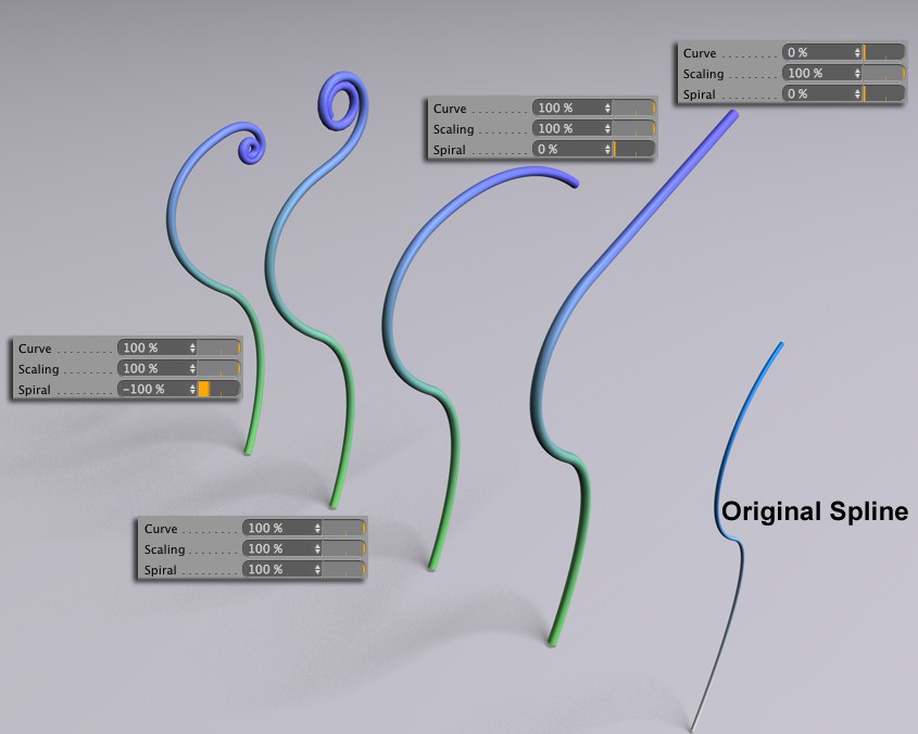
Curve [-∞..+∞%]
Curve [-∞..+∞%]
The effect of this setting can best be seen if the Spiral value is set to 0%. A value of 0% will cause the MoSpline to be pushed beyond its limits in a straight line. Increasing the Spiral value will increase the amount of spiraling accordingly.
Scaling [-∞..+∞%]
Scaling [-∞..+∞%]
This setting will only influence the Spline segment’s if its width is varied, for example if the Spline was given an effect. The Scale setting can then be used to influence the MoSpline’s Width and even its shape.
Spiral [-∞..+∞%]
Spiral [-∞..+∞%]
If the MoSpline should curl when extended, set this value to not equal 0. Positive and negative values will cause the MoSpline to spiral in opposite directions. The greater the value differs from 0 the greater the spiral effect will be.
If Mode is set to Spline the shape of the resulting spirals will be nearly impossible to predict because unexpected twists can quickly result. Therefore, the following options are recommended for source Splines:
- Type: Cubic, Akima
- Intermediate Points: Natural, Uniform
The spiral is calculated based on the last four points of the source spline. If the angles between the lines created by these points increase the spiral will curve in one direction and in the other if the angles decrease (more information can be found here: Generation Mode).
Spiral Scale [-∞..+∞%]
Spiral Scale [-∞..+∞%]
Use this setting to modify a spiral’s size without affecting its shape.
Splines whose ends vary too greatly over a short distance can exhibit unwanted, discontinuous extensions. Enabling this option will help create a more harmonious extension.
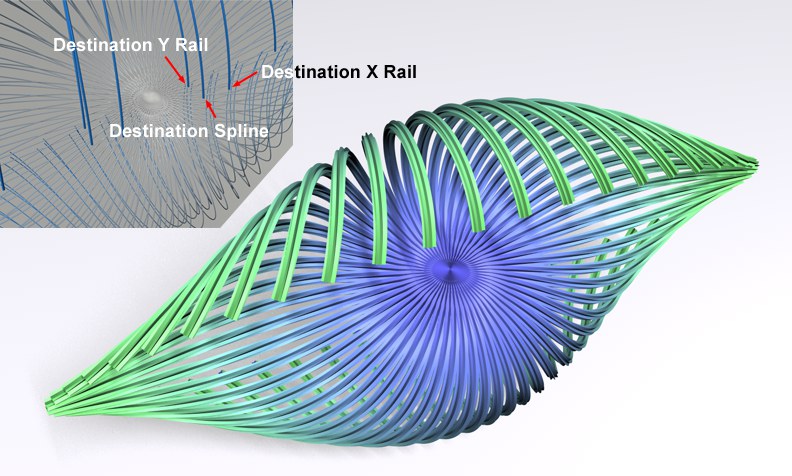 Each MoSpline can be broken down into three real Splines.
Since not all functions work with MoSplines, the following three settings can be used to create "real" Spline objects using MoSpline. To do so, drag a Spline object, which can also be an empty object, into the corresponding field (Spline Primitives will not work).
Also, if a MoSpline object is in a fixed hierarchy from which it cannot be removed, the Spline Generation functionality can be used to create a Spline (which can be placed freely within the hierarchy) for any purpose.
This spline reflects the shape of the MoSpline.
Destination X Rail
Destination Y Rail
The Rail Splines that run in the X and Y directions, respectively.
This field functions the same as the two aforementioned fields but for polygon objects. If you create polygons using Rules (see also Example, creating polygons’), these can be assigned directly to a polygon object. This is always recommended if the geometry that is dynamically created by the MoSpline object should be used for additional purposes, for which the MoSpline object itself cannot be directly used (if, for example, the Cloner object should create clones on the geometry that was generated).
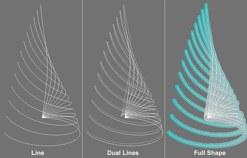
This setting defines how the unrendered MoSpline should appear in the Editor Window. The more simple the display mode, the faster the display will react in the Editor Window. The