Teeth
This tab contains several settings that vary depending on the Type of teeth selected.
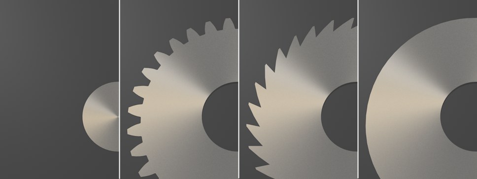 From left to right, Type set to None, Involute, Ratchet, Flat.
You can select from:
- None: Only the Inlay or milling groove will be displayed.
- Involute: An actual cogwheel.
- Ratchet: A ratchet/saw tooth profile.
- Flat: A radial profile.
Please note the following for the Involute type: This is the most important type for mechanical engineering. The teeth are formed so that only a single point of contact exists at which perpendicular force will be exerted. The cogwheel teeth have a unique shape from which many of the following are mutually dependent. For example, if one of the Radius values is modified, numerous other settings will automatically be modified to ensure that the teeth maintain an involuted shape.
If two cogwheels are combined (paired), the Module, Teeth and Pressure Angle settings must be identical for both cogwheels! Otherwise they cannot function together.
Good to know for animation: The cogwheel rotation angles’ behavior is proportional to the tooth(count) ratio of both cogwheels. The following formula is used to calculate the exact distance between the cogwheels’ axes: Axis distance = (tooth count a + tooth count b) / 2 * Module.
This is given when both cogwheels’ pitch circles (the center orange circles) touch (refer to the following Project file).

This value defines the total number of cogwheel teeth. Note that modifying this value will cause the radius of the teeth to change accordingly. Enable the Lock Radius option to prevent this from happening.
If this option is disabled, the various Radius settings (see below) will be adjusted automatically depending on the Teeth value defined; contrary to the size of the cogwheel itself, the size of the teeth will remain constant.
If this option is enabled, the size of the teeth will be more-or-less maintained and the shape and the cogwheel size and shape will change, depending on the Teeth value defined. However, the shape of the involute cogwheel will no longer be technically correct because the shape of the teeth will change.
Use this value to rotate the teeth independent of the rest of the cogwheel. This can, for example, be useful for fine-tuning the teeth to show two interlocked teeth.
When real-world cogwheels are produced, tiny regions are (unintentionally) cut away at the root. The fewer teeth a cogwheel has, the more pronounced this is and the smaller the pressure angle will be. Enable the Undercut option to counter this effect.
Root Radius, Addendum Radius, Pitch Radius, Diametral Pitch, Dedendum, Pressure Angle
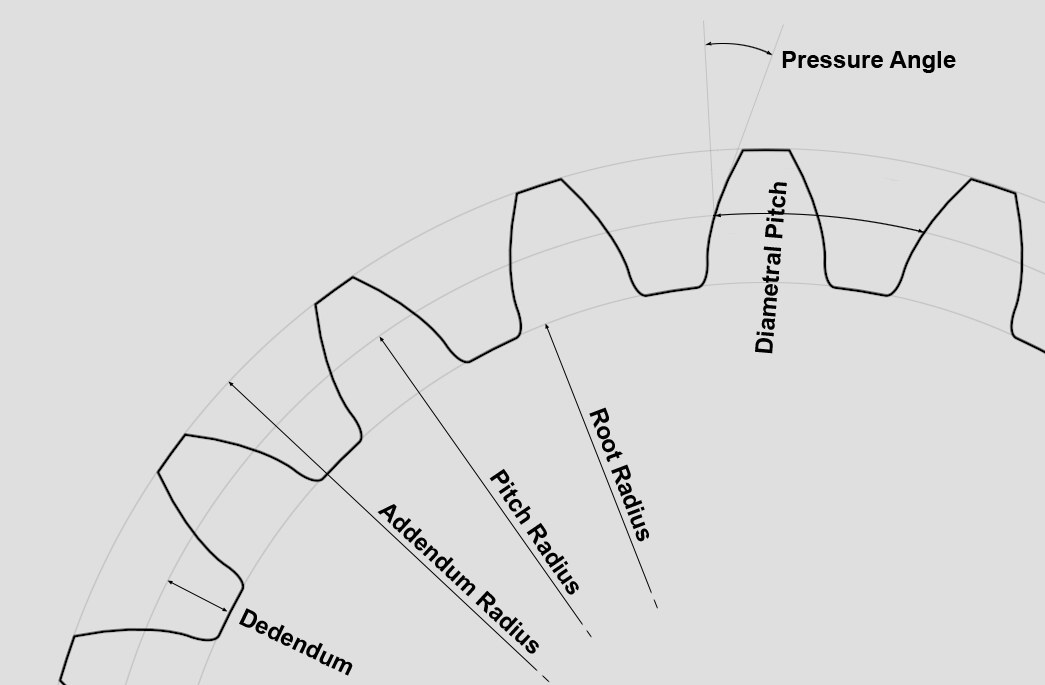 Various cogwheel settings
These settings, most of which are mutually dependent on one another and are modified automatically (see above), are used to define the crucial cogwheel properties.
This defines the radius at the foot of each tooth (see image). This value can also be modified interactively in the Viewport using the handles.
This value defines the radial distance between a point on one tooth and the corresponding point on an adjacent tooth. This is a crucial radius used to calculate the force and torque for a cogwheel (see image).
This value defines the distance from the pitch surface to the outermost point of the tooth. This value can also be modified interactively in the Viewport using the handles.
This value characterizes the tooth size and is a result of the Pitch Radius and Teeth values: Module = 2 * Pitch Radius / Teeth. This is an important indicator primarily in European countries.
This value defines the radial distance between two teeth. This parameter is a reciprocal value of the Module value, i.e.,; Diametral Pitch = Teeth / (2 * Pitch Radius). This indicator is widely used in the USA, for example.
This value represents the difference between the Diametral Pitch and the Root Radius values.
This value defines the angle of the tooth’s side. This is a typical property of teeth that pertains to the perpendicular exertion of force on a tooth. This value is most often 20° in the field of mechanical engineering.
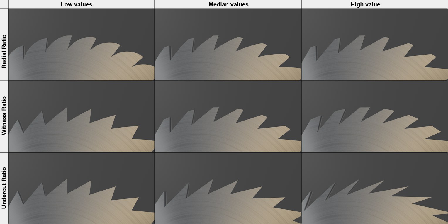 Various values for ratchet ratios.
This and the following settings only apply to the Ratchet Type. It’s a good idea to play around with these settings to see which interesting shapes can be created (in particular those with few teeth …). The Radial Ratio value defines the degree of curvature for the backside of the teeth. The smaller the value, the rounder the tooth side will be. Larger values produce correspondingly more linear sides.
This value defines the degree of rounding for the traverse edge at the tooth’s tip - as is commonly seen on saw blades. A value of 0 will produce a sharp point and larger values will produce correspondingly longer edges.
This value can be used to move the base corner of the teeth back. The larger the value, the farther back this point will be moved.