Animation
This tab contains the most important settings for controlling and animating the Motion Camera.
You are probably already familiar with concept of having cameras follow along Splines if you’ve used the Align to Path function. The Motion Camera tag offers 2 additional Path Splines (with corresponding Rail Splines that can be used to steplessly dissolve two cameras (without setting a single keyframe); click on the small arrow to the left of Camera Pos A/B Curve and Blend <-> A/B.
Enable this option to activate or deactivate the Spline functionality.
Enable this option if you want the camera to move tangentially to the Spline (which will normally be the case). Otherwise the camera orientation will remain unchanged and the camera person will follow the Spline.
Path Spline A
Rail Spline A
Path Spline B
Rail Spline B
Using these fields you can define a total of 4 Splines that can be used to create 2 complete spline camera animations and dissolve between them using the Blend A<->B options described below.
An (optional) Rail Spline can be used to achieve the following bank:
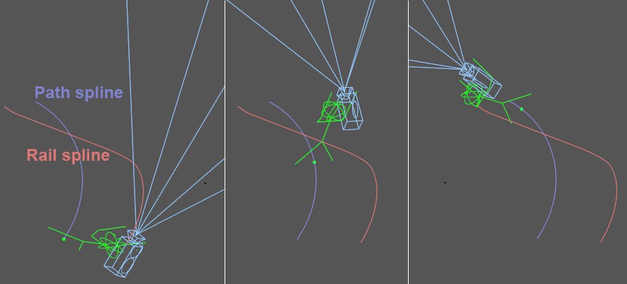
As the camera person moves along the Path Spline (e.g., Path Spline A), the Rail Spline (e.g., Rail Spline A) causes the camera person to bank (’lean’ into the curve) around its Z axis (the view axis) or length axis. The bank takes place in the direction of the current Rail Spline position defined by the Camera Position A and Camera Position B settings. Note that the Tangential option is activated when using Rail Splines. This is necessary in order to create useful orientations.
Use this value to define the position on the Spline in the Path Spline A field.
This curve defines the animation progression between the Start and End points (click on the small arrow at the right of the main parameter). The corresponding main parameter (e.g, Camera Position A) will be animated at 100% within this rage.
Enable this option if the corresponding main parameter (e.g., Camera Position A) should be animated without using keyframes.
This is the range within which the corresponding parameter (e.g., Camera Position A) will be animated from 0% to 100%.
Use this value to define the position of the Spline in the Path Spline B field.
This curve defines the animation progression between the Start and End points (click on the small arrow at the right of the main parameter). The corresponding main parameter (e.g, Camera Position A) will be animated at 100% within this rage.
Enable this option if the corresponding main parameter (e.g., Camera Position A) should be animated without using keyframes.
This is the range within which the corresponding parameter (e.g., Camera Position A) will be animated from 0% to 100%.
Use this setting to steplessly define the blending (dissolve) between Cam Position A and Camera Position B.
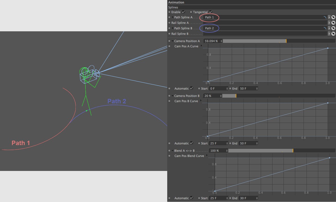
In the example above you can see how the camera blends from Path 1 to Path 2 without setting a single keyframe. The Blend A<->B quickly blends Camera Position A to Camera Position B at frame 25.
This curve defines the animation progression between the Start and End points (click on the small arrow at the right of the main parameter). The corresponding main parameter (e.g, Camera Position A) will be animated at 100% within this rage.
Enable this option if the corresponding main parameter (e.g., Camera Position A) should be animated without using keyframes.
This is the range within which the corresponding parameter (e.g., Camera Position A) will be animated from 0% to 100%.
Use this setting to define the strength of the Splines settings steplessly anywhere between 0% and 100%.
The Motion Camera tag can use up to 4 different objects as target objects and can blend steplessly back and forth between them. Note that the Target settings affect the camera person’s head (if the camera lies on the camera person’s shoulder it cannot make a complete rotation).
Enables or disables the Target settings.
Using the Rig tab’s settings, the camera can be moved and panned manually - and it can occur that a target object falls out of the field of view. If the Compensate Aberration option is enabled, this object will again be placed at the center of the camera’s field of view.
The Motion tab’s settings can also cause objects to diverge from the camera’s field of view - an effect that can be minimized by enabling this option.
Target A1
Target A2
Target B1
Target B2
In these fields, 4 target objects can be defined in 2 groups, A and B. The following blend options are available:
- Blend between Target A1 and Target A2 (results in Position A)
- Blend between Target B1 and Target B2 (results in Position B)
- Blend between Position A and Position B
A skilled combination of the three Target settings below can be used to steplessly blend between all 4 targets!
If a Spline is placed into one of these fields, an additional slider will be made available for that field with which the position on the Spline can be defined.
Target A1 Pos [0..100%]
Target A2 Pos [0..100%]
Target B1 Pos [0..100%]
Target B2 Pos [0..100%]
Use these settings to precisely define the position of spline Target objects along the Spline. This in turn makes it possible to very precisely define the camera’s orientation. This is recommended, for example, when panning horizontally across large angles (e.g., 180°). If Target objects are also used (i.e., no Splines) that are located in front of as well as behind the camera, the camera will also have to pan vertically and not only horizontally. This can be easily solved by using a hemispherical target Spline.
The object defined here defines the orientation of the Y axis with regard to the banking of the camera person’s head (in contrast to the Rail Spline that provides an Up Vector for the camera person’s entire body).
Target Pos A1 <-> A2 [0..100%]
Use this slider to pan steplessly between the positions A1 and A2.
Target Pos B1 <-> B2 [0..100%]
Use this slider to pan steplessly between the positions B1 and B2 (if B is used when Target Pos A<->B is defined accordingly).
Use this slider to steplessly blend between Target Positions in group A and the Target Positions in group B.
Blend A Curve
Blend B Curve
Blend AB Curve
Use these curves to fine-tune the Target Position settings. These curves define the course of the parameter (basically the same as the animation F-Curves). You can simply animate the Target Position settings with linear interpolation between 0% and 100% without having to deal with F-Curves.
Intensity [0..100%]
Intensity Curve
Use these settings to steplessly define the effect of the Target Position settings between 0% (no effect) and 100% (full effect).
It’s not always easy to keep an object that is constantly moving and changing direction in the camera’s field of view. The Chase Object function, however, makes this a snap.
It can be compared to having the camera attached to an object with a rope - and the camera will simply be pulled along by the targeted object. It doesn’t matter how the chased object is moved, whether by keyframes, Expressions or Dynamics.
It can help to define an object in the Rig tab’s Link field as the camera’s start and orientation location.
Note that Chase Object is a dynamic effect, i.e., the animation should be allowed to run through - scrolling back and forth in the Timeline can lead to unwanted results. Furthermore, the animation should be baked before it’s rendered with Team Render.
The Dynamics tab’s Damp settings can be used to avoid jerky movements.
Enables or disables the Chase Object function.
Drag the object to be followed by the camera into this field.
Max. Distance [0..+∞m]
Min. Distance [0..+∞m]
Use these values to define the minimum and maximum distance the camera can be from the chased object. If the minimum distance is exceeded, the camera will be pulled; if the maximum distance is exceeded, the camera will be pulled; if the distance falls short of the maximum distance the camera will slow or come to a halt and rotate to follow the object. If the camera gets too close it will be pushed away from the chased object.
If both values are equal, the camera will follow the object as if it were attached via a solid rod.
This effect can be likened to the leaning (into a curve) of a motorrcyle rider, which is done to counter the centrifugal force. The same occurs for the camera person, including the camera, when this function is enabled. If this effect is applied subtly it will contribute a great deal to a more realistic camera motion.
Note that Automatic Banking is a dynamic effect, i.e., the animation should be allowed to run through - scrolling back and forth in the Timeline can lead to unwanted results. Furthermore, the animation should be baked before it’s rendered with Team Render.
Enables or disables the Automatic Banking function.
Use this setting to define the degree to which the banking should occur. Larger values can be compared to the banking of a motorcycle or helicopter. Note that very large values can result in unstable camera motion. Larger values will generally require correspondingly larger Dampen values, depending on the nature of the bank.
Strong or abrupt changes in the camera’s motion can lead to overcompensation in banking. In such cases or with larger Intensity values, the Dampen value should be increased so the camera no longer behaves as ,nervously’.