The Storyboard
The Storyboard works hand in hand with your Stored Views, allowing you to arrange these views in any order and combine them with timing behavior. This makes it very quick to define animations consisting of camera movements or changes in lighting conditions, for example.
Click on the term Storyboard at the top right of the Redshift window to make the Storyboard layout visible.
Quick Navigation
The Storyboard Workflow
Working with the Storyboard follows a fixed workflow (see Figure 1). First, we assume that the Storyboard layout has been activated by clicking on it (see 1) and that you have already saved at least one view (see 3) as an entry in the Stored Views panel (see 2). Think of these views as data packages in which, for example, the positions and visibilities of all objects, the camera perspective, any scatter settings, and environment and material settings can be saved. In short, a Stored View represents the state of the scene in the context of the Storyboard, which you can use as a starting point for rendering.
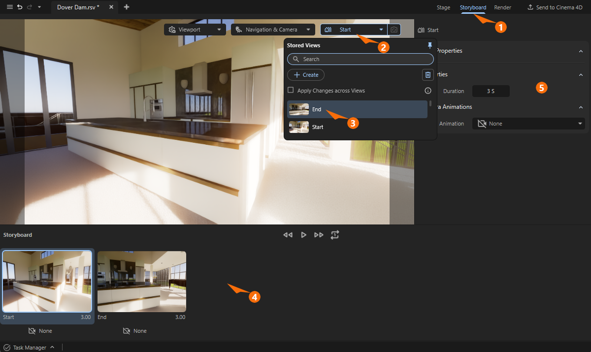
To do this, simply drag the desired view from the Stored Views list into the Storyboard area below the viewport (number 4). The views are displayed there as slides and can be sorted as desired with the mouse or removed from the Storyboard by clicking on them and pressing the Del key. However, they remain in the Stored Views. Each view stored in the Storyboard can be selected by clicking on it and then displays its settings in the Attribute Manager on the right (number 5).
Think of the views in the Storyboard as individual scenes in an animation or film. If there are multiple views in the Storyboard, the output animation will show a hard cut when transitioning from one view to the next. Although there is no interpolation between different object positions in adjacent views in the Storyboard, each view offers different methods for camera movements that can be implemented during a selected Duration.
Animation Options
To define an animation, a single view in the Storyboard is sufficient. Select it and use the Duration value in the Properties group of the Attribute Manager to specify the length of time the animation should last for this setting. The Duration value is specified in seconds and also appears below the thumbnails in the Storyboard. Together with the Frame Rate specification from the Render Settings, this results in the final number of frames actually rendered during an animation.
The Duration ensures that the scene stored in the view is displayed for a certain time during the animation. However, this alone does not necessarily mean that anything moves. Although there are automatically animated elements, such as the clouds in an Environment sky, which can be automatically moved by wind, the position and viewing direction of the camera, for example, remain static by default during the Duration. The following settings are available for this purpose.
Camera Animation
Here you can bring your scenes to life by choosing between different camera movements typical in film productions. For each view stored in the Storyboard, you can select a type of camera animation, the name of which can then be read in the center below the slide of the view in the Storyboard. By default, there is None activated for the camera animation of each view.
If your camera uses active Depth of Field simulation, be sure to assign an object in the Auto Focus field for calculating the Distance value. This is the only way to ensure that a selected object remains in focus even during a camera animation.
None
This is the default setting for every new view added to the storyboard. The camera remains static regardless of the duration selected. This can be used, for example, for static viewing angles that are to be inserted within the animation.
Dolly
In this mode, the camera is guided as if on a straight rail. The direction of this rail can be freely selected relative to the camera's axis system using the Direction setting. It is also possible to influence the camera's viewing direction so that it is aligned with a specific object in the scene at the beginning of the animation.
Let's consider the available options in the following Illustration 1. Here, we are looking from the kitchen countertop toward the camera (see also Figure 1 for reference), whose axis system is marked in the standard colors blue (Z-axis, Front or camera's direction of view), green (Y-axis or Up), and red (X-axis or Right).
With the Direction Front option, the camera is moved toward the blue axis. As indicated in the illustration, this brings the camera closer and closer to the countertop, since the camera was initially placed higher than the countertop but also tilted slightly downward. To avoid such approaches or even collisions, the Keep Camera Level option can also be activated. The camera is then automatically kept at the same height during the movement, even if it is tilted slightly up or down. In Illustration 1, this corrected movement path corresponds to the orange line.
The distance that the camera should cover during the Duration specified for this view is set in Radius. This means that the camera will automatically move faster if the Radius is increased. It is therefore advisable to first configure the Direction and Radius to define the end point of the camera flight and then finally edit the Duration to adjust the speed of movement. In this context, it is very helpful that you do not have to set this at random, but can also find typical playback options below the viewport that allow you to view the animation of the Storyboard directly.
Playback Options
|
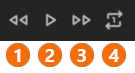
With these icons you can control the playback of your Storyboard animation directly in the viewport. 1Jump back to the beginning of the storyboard animation 2Play or stop animation playback in the viewport. 3Jump back to the end of the storyboard animation 4Clicking on this icon, you can switch between the two available options:
|
'Look At' Function
Thanks to the ability to link any object, the Dolly function can be expanded even further. Although the camera always moves in the direction of one of the camera axes, the camera itself can continuously focus on the assigned Look At object, keeping it in the center of the image.
To do this, click on the eyedropper icon next to the Look At field and then directly on the object in the viewport that you want the camera to point at. The position of the camera remains unchanged.
The Look At object will then automatically remain in the center of the image while the camera moves along the originally selected Direction. If you made a mistake when assigning the Look At object, you can remove it by selecting Clear from the context menu. The camera alignment originally saved in the Stored View will then be restored. The following video demonstrates this Look At functionality.
Reverse Option
Finally, the direction of movement of the camera can also be inverted by Reverse. The camera movement then starts at the end and ends at the original starting point. This option is also available for the other camera animations.
Advanced Settings: Interpolation
This option is also available for all camera animation types and determines how the camera's acceleration behavior is calculated. Normally, every object has a mass and therefore resists changes in its position or speed (inertia). The Smooth Interpolation mimics precisely this effect. The object — in this case, our camera — first starts moving slowly, then speeds up, and finally slows down again just as slowly until it comes to a stop at the end of the movement. This results in very smooth and natural-looking camera movements.
With Linear Interpolation, on the other hand, the speed of the camera remains constant throughout, meaning it starts and ends abruptly. This can be advantageous if you want to edit several linear camera movements together later, as it is then no longer possible to tell whether a movement has been going on for some time or has just begun.
The following video demonstrates the different effects of Linear and Smooth Interpolation using animated cubes as an example. Both cubes cover the same distance in the same time, but show different accelerations due to the different interpolation.
Pan
In this mode, the position of the camera remains static; only the camera's viewing direction is changed. This camera animation can therefore be compared to a pan performed on a tripod. Some of the settings for this are already familiar from Dolly mode and will therefore not be discussed in detail here.
Direction
This setting determines the direction in which the camera should pan. The camera can be rotated to the left and right or up and down. The following video shows an example of a pan to the right. You specify how far to rotate using Rotation Angle.
Rotation Angle
This angle specifies how far the pan should move within the specified time (see Duration). To use the camera rotated by the Rotation Angle as the initial state, the Reverse option can be activated. In this case, the pan will be inverted and end in the original camera position that was saved in the view.
Reverse
With Reverse activated, the pan animation will be inverted and end in the original camera position that was saved in the view.
Advanced Settings: Interpolation
With Smooth Interpolation the camera first starts moving slowly, then speeds up, and finally slows down again just as slowly until it comes to a stop at the end of the movement. This results in very smooth and natural-looking camera movements.
With Linear Interpolation, on the other hand, the speed of the camera rotation remains constant throughout, meaning it starts and ends abruptly. This can be advantageous if you want to edit several linear camera movements together later, as it is then no longer possible to tell whether a movement has been going on for some time or has just begun.
The following video demonstrates the different effects of Linear and Smooth Interpolation using animated capsules as an example. Both capsules cover the same rotation range in the same time, but show different accelerations due to the different interpolation.
Orbit
In this mode, the camera can be moved along a circular arc and rotated automatically. This can appear like a combination of Pan and Dolly. The change in perspective of the camera along this animation path can create particularly impressive camera movements.
Orbit - Object Properties
In order to fully describe the orbital trajectory, various parameters must be taken into account. For this reason, we will discuss them here in context:
- Orbit: Here you can select the direction in which the camera should move. You can choose between trajectories to the Left or Right, as well as Up or Down.
- Rotation Angle: The length of the curved trajectory is determined by this angle. In the illustrative video above, this angle is shown as an orange area. However, the length of the arc also depends on the Distance specified by the center point of the circular trajectory.
- Distance: This distance determines the position of the center point around which the circular path is calculated. The camera's viewing direction is extended by this amount (see blue arrow in the illustration video above). A circle is then drawn around this point, passing through the camera's starting position. As a result, when the Distance values are very small, the camera remains almost static in its position and only rotates. The effect is then very similar to Pan animation. Similarly, with very large Distance values, the camera's trajectory can appear linear, similar to Dolly mode. In any case, however, the camera remains aligned with the calculated center point of the circular path during movement. Please note that the Distance is set automatically if you assign a Target Object.Important:
If you manually change the value for Distance AFTER a Target Object has been assigned, the camera will move toward or away from the position of the Target Object. This may change the camera position actually stored in the view being used.
- Target Object: By default, during its animation, the camera aims at the position resulting from extending the viewing direction by the value entered in Distance. As already explained for Dolly mode, any object can be linked here to which the camera should aim throughout the entire animation. This object then remains permanently in the center of the frame during the animation. To assign a Target Object , first click on the Eyedropper icon to the right of the Target Object field and then click on the object in the viewport that you want the camera to target. Note that the Distance for the assigned Target Object is calculated automatically, so that the position of this object essentially becomes the new center point of the circular Orbit animation.
Advanced Settings: Interpolation
With Smooth Interpolation the camera first starts moving slowly, then speeds up, and finally slows down again just as slowly until it comes to a stop at the end of the movement. This results in very smooth and natural-looking camera movements.
With Linear Interpolation, on the other hand, the speed of the camera animation remains constant throughout, meaning it starts and ends abruptly. This can be advantageous if you want to edit several linear camera movements together later, as it is then no longer possible to tell whether a movement has been going on for some time or has just begun.
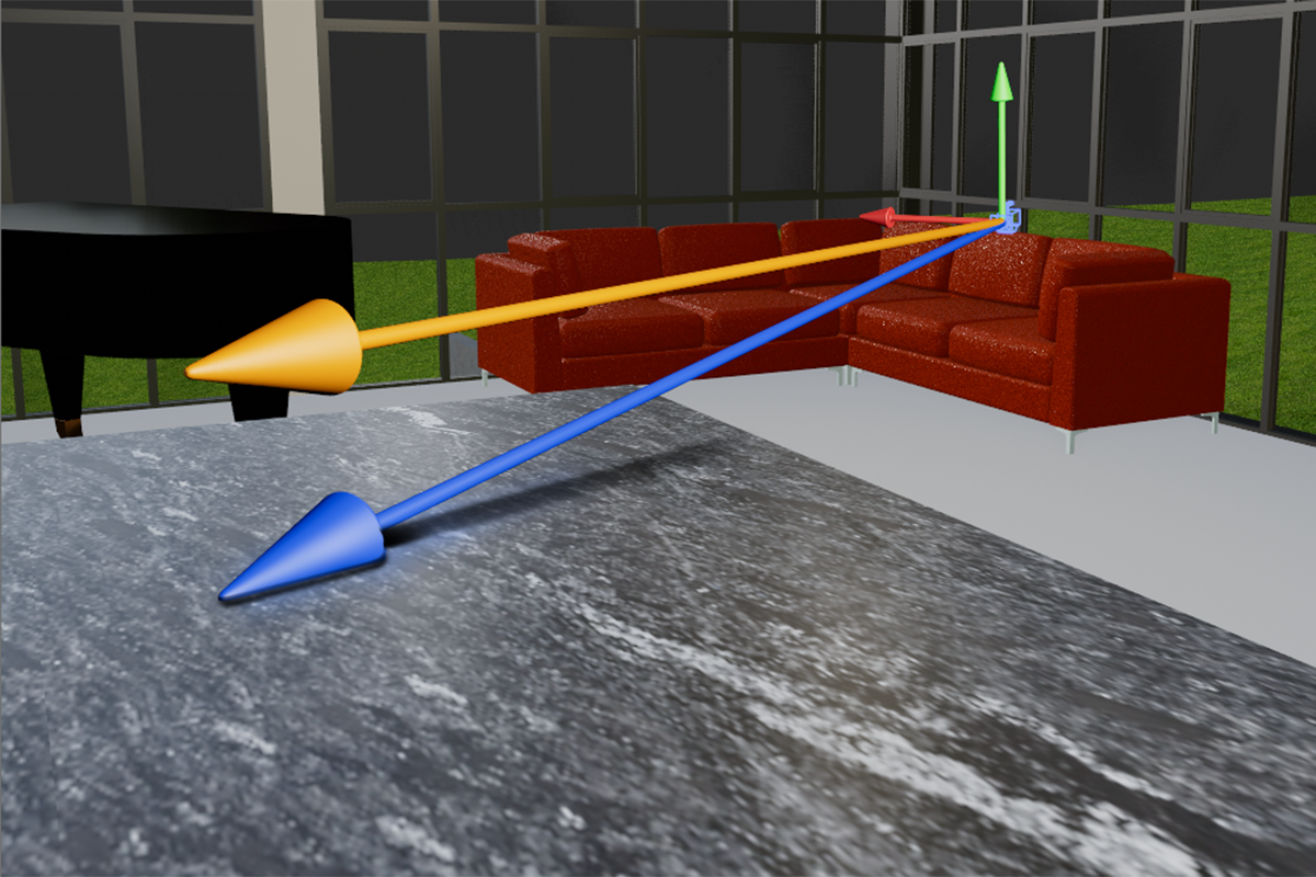
The following video demonstrates the different effects of Linear and Smooth Interpolation using arrow shapes as an example. Both arrows cover the same orbit path around a blue Target Object in the same time, but show different accelerations due to the different interpolation.
Environment Animation
Additional parameters on the selected view can be used to specify the direction and speed of the cloud movement during the animation. These values are only relevant if you enabled clouds by selecting a Coverage value for clouds of more than 0% in the Environment settings.
-
Speed determines the speed at which the clouds move. A value of 0 results in static clouds. Higher values cause the clouds to move across the sky during the animation. The direction of movement can be set separately using the Direction value. In any case, the clouds are not simply displaced, but also change their structure during this movement.
-
Direction specifies the angle at which the wind blows and shifts the clouds. The 0° angle corresponds to the positive X-axis direction of the world system. At 90°, the clouds would be shifted in the positive Z direction of the world system. Similarly, 180° would result in a shift in the negative X direction and 270° in a shift in the negative Z direction.