Picture Viewer
![]()
General
The Picture Viewer is Cinema 4D's output window. This is where rendered images and animations are displayed if the corresponding option is selected in the Render Settings (see ![]() Render to Picture Viewer). Images rendered for a given session can be called up any time from the History tab as long as the session is open.
Render to Picture Viewer). Images rendered for a given session can be called up any time from the History tab as long as the session is open.
The integrated RAM player lets an animation be played directly in the Picture Viewer without having to save it in advance as a video.
The Picture Viewer contains a filter with command image settings such as brightness, contrast, etc. Images and animations can be saved from the Picture Viewer in any available (in Cinema 4D) image or video format. Images or animations (incl. sound) can be loaded into the Picture Viewer as well. This lets the Picture Viewer work as a conversion tool with which image and video formats can be converted or even individual images extracted from a video.
Interface
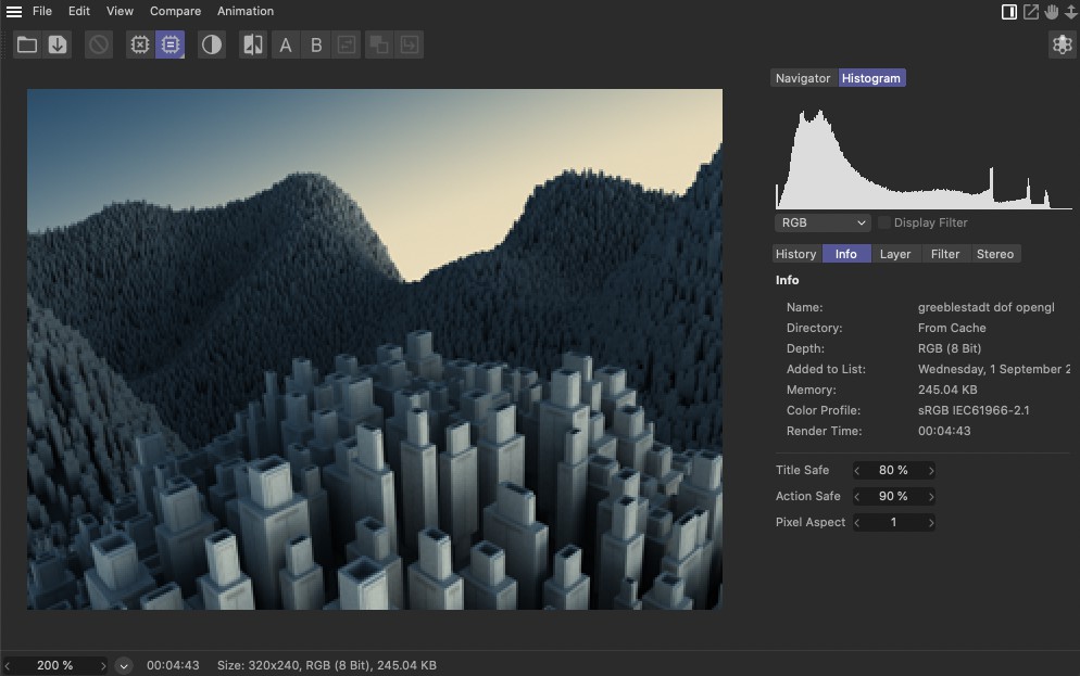
The largest part of the Picture Viewer is taken up by its display window. Images will be displayed in accordance to the settings defined in the History and Layer tabs. The Filter tab's settings let you adjust the primary image properties. Any modifications made to these settings will be displayed directly in the Picture Viewer.
Adjusting the display information
With the introduction of Cinema 4D 2023.0, the OpenColorIO color management can, among other things, be used with ACES color spaces, which can be activated in the Project Settings menu. This makes it possible to use very large color spaces for rendering as well as for archiving and forwarding in its original, uncurtailed color values. Since current display devices generally don't offer such large color spaces, the color data on the display, e.g., a monitor, has to be adapted accordingly, i.e., converted via a tonal correction.
In the Project Settings menu you will find a View Transform setting, which will automatically be applied for displaying your rendering in the Picture Viewer. However, if you want to test other options for the display transformation you can do this directly in the Picture Viewer. This will not change the color space or the color profile of the saved file. You can, however, use the Save Image As .. command in the Picture Viewer's File menu to bake the active display information into the image. However, in doing so you will lose the advantage of the continuous color management with the ability to flexibly adjust colors and color spaces in post-production.
Don't forget that the Picture Viewer can also display images from other projects that were rendered with a different color management. This means that the view made available can differ from that of the other project. Furthermore, the view information can only be modified for 32-bit images. For 8-bit images the View Transform information is always defined.
On the left side of the image above you can see the selection menu for the Transform menu if the Basic color management is active in the Transform mode in the Project Settings menu. The displayed image can only assume the color space transformation for the sRGB color space (Project setting), the color profile within the image itself (Imbedded) or the color space of the monitor (as a rule sRGB).
On the right side of the image you can see the complete menu if OCIO Color Management with ACES configuration is active. You will have access to the available color spaces for the view space transformation.
To summarize, the following options are available:
- Off: Disables the tonal correction for displaying images.
- Project: Uses the transformation for the view space as is defined in the Preferences menu.
- Embedded: Uses the color profile that is imbedded in the image.
- Monitor Color Space: Uses your monitor's device profile and adjusts the colors accordingly.
- ACES 1.0 SDR Video: This is a OCIO display option that also goes by the name "sRGB monitor (in part EOTF)". EOTF stands for Electro Optical Transfer Function used in the color sciences and describes the conversion functions between digital color values and brightness that can be displayed on the respective display device. The result is a gamma-based sRGB data set.
- Log: This is the abbreviation for Logarithmic Gamma Curve and is the preferred method of colorists for viewing and working with content. The image contrast is reduced greatly in particular in the dark and bright regions of the image, which produces more visible detail.
- Raw: All color values will be treated as data values, which can be useful when evaluating individual multi-passes in particular if these are used for saving data (e.g., for masks or a Z buffer).
- Un-tone-mapped: Normally the view space of a display device is smaller than the linear render space. Colors that are read out will therefore be corrected via a tonal correction in order to be displayed. Here you can deactivate this tonal correction. The color values will then be displayed unchanged and will no longer be clipped, even if they lie outside of the displayable color space.
Layout Options and Navigation
At the top right of the Picture Viewer's dialog window are these three icons:

- Opening a new Picture Viewer
From left to right:
- Displays/hides the window's tabs
- Moves the Picture Viewer's clipping region
- Scales the Picture Viewer's clipping region
The following interactive functions are also available:
- Click and drag in the clipping region to move it
-
Simultaneously pressing the 2 key will scale the image (your mouse wheel will do the same)
-
Double-clicking on an image scales it to 100%; double-clicking again will scale it to full-screen.
-
Simultaneously pressing the Ctrl key will display the coordinates and RGB values at the cursor's location in the Picture Viewer's status bar.
-
Right-clicking will open a context menu from which you can select an alternate background color.
RAM Player
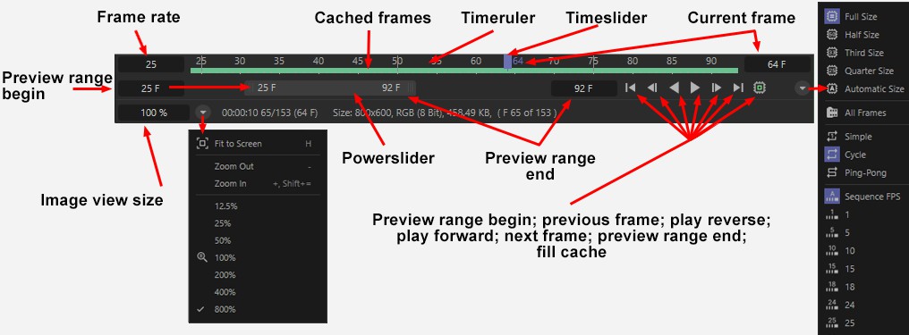
If an animation or video is loaded into the Picture Viewer a control panel similar to the Animation Palette will be displayed at the bottom of the Picture Viewer's dialog window, which is controlled via the RAM player:
 You can switch between Play and Stop by pressing the space bar on your keyboard.
What is a RAM player? Basically it's nothing more than a function that loads an animation's images temporarily into dynamic memory so they can be played back in real-time! This means it is not necessary to first render an animation in video format so it can be played in another external application.
This is not a trivial function since images will be rendered in full resolution and stored uncompressed in the RAM - and uncompressed images tend to take up a lot of memory! A series of uncompressed JPEG images can quickly turn into several Gigabytes!
In the Preferences menu's Memory dialog window you will find the Memory (MB) parameter. This value defines the amount of memory that will be allocated for caching rendered images.
Note that sound will only be played back if the corresponding option is enabled (loudspeaker icon) and the ![]() All Frames option is disabled in the Picture Viewer's Animation / Frame Rate menu.
All Frames option is disabled in the Picture Viewer's Animation / Frame Rate menu.
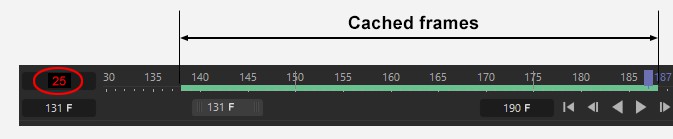
The cached images are displayed in the Timeline. If the series of images is played and the Timeslider (the green rectangular marker) moves beyond this green range new images (from the hard drive) will be loaded and the oldest images will be removed - which rarely works in real-time. In such instances the frame rate value will be displayed in red. This means that playing the animation in real-time is not possible and frames will be skipped. Any images omitted from a sequence will be highlighted in red.
The Timeline can be modified interactively using the hotkeys 1 (move) and 2 (scale).
The range displayed in the Timeline and defined by the Powerslider ("preview range") is the frame range that will be played exclusively. The Powerslider can be used to navigate temporally through your frame range. Its scalable length (drag on the left or right end) defines the range above ("preview range"). You can double-click on the frame numbers on the left or right end of the Powerslider to quickly define a preview range manually. Clicking on the Powerslider while simultaneously pressing Ctrl + a on your keyboard will set the Powerslider to the complete length of all frames. While simultaneously pressing the Alt while dragging the slider will be scaled at both ends.
Almost all of the RAM player's controls can also be found as command in the Picture Viewer's menu.
Tabs
Navigator
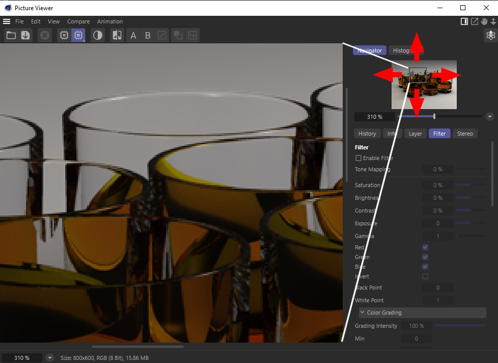
The Navigator displays the rendered image in preview size. Depending on the Zoom factor, the visible region with a moveable square will be displayed. Double-clicking in the Navigator will automatically set the Zoom to 100%.
By Shift+clicking the square can be moved horizontally or vertically. A scalable region can be selected by Ctrl/Cmd+clicking.
Below the Navigator's preview window is a slider with which the image at the left can be scaled. To the right of the slider is a button that opens a menu that contains numerous options, including Zoom.
Histogram
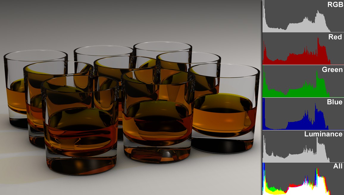
The Histogram displays a static dispersion of brightness, color and luminance information for an image (or Multi-Pass channel). Peaks in the Histogram represent values that occur more often. If you take a look at the image above you will see that the Histogram is quite "empty" at the right. This isn't surprising because the image is quite dark and contains practically no white regions. By looking at the Histogram you can quickly tell if an image is over exposed or if its contrast is correct, for example.
The following Histogram settings are available:
Mode Selection Menu
Here you can define which value or color channel should be displayed (see image above).
Luminance is, simply put, the image's brightness; green is, for example, carries more weight than red or blue (the human eye sees green as brighter than red/blue).
Display Filter
If enabled, the effects of the filter will also be taken into account, i.e., you can interactively change filter values and preview them in real time in the Histogram (the Filter Histogram will be displayed in addition to the existing Histogram). For example, if you were to reduce the White Point for the example above, the Histogram would expand to the right.
History
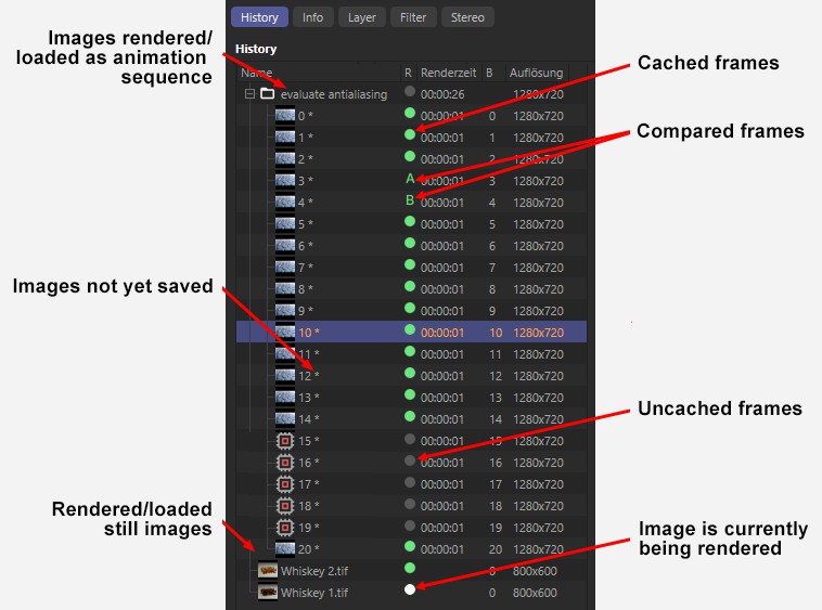
The top part of the History tab's list shows all rendered or loaded images for the current session. This list will remain empty until a rendering or render session takes place.
Click on one of the list entries to display it in the Picture Viewer. Animation frames will be saved to a directory named according to the scene name (newly rendered) or file name (loaded images). Image names with a * next to them represent images that have not been saved. The History tab contains the following columns:
- Name: Image or directory name
- Resolution: Image resolution in pixels
-
R: Image information
- Green: cached
- Gray: not cached
- Orange: currently being rendered
- A/B: these images are currently being compared - F: The frame number
Double-clicking on an image name will highlight the name for renaming (single images only - no sequences). This new name will be maintained if saved at a later point.
Frames can be selected using the usual hotkeys: Shift - from to selection; Ctrl - add individual frames to or them remove a given selection. Individual images or complete directories can be dragged and dropped to a different location in the hierarchy. Individual images can be copied by simultaneously pressing the Ctrl key.
The arrow keys on your keyboard can be used to navigate up or down through the hierarchy or open (right) or close (left) directories.
Press the right mouse button to open an context menu whose commands can all be found in the Picture Viewer menu with the exception of the following:
Displays the file in the corresponding application on your computer. This command cannot be called up if the image is not on the hard drive and only saved to the cache.
At the bottom half of the History tab are several self-explanatory parameters regarding the selected image. The total Render Time will also be displayed for newly rendered images or animations.
Creates new, separate render presets for rendered images or image sequences for the current Cinema 4D session. This can be very practical if you make several test renderings using different render settings and want to select the settings that fit best. The render preset name will correspond to the name with which the rendering was save or the scene name.
Information
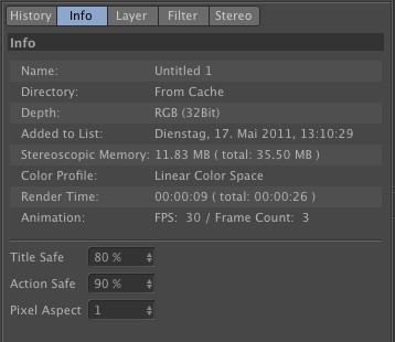
Here you will find several self-explanatory pieces of information regarding the selected image. For newly rendered images and sequences the render time per image and the total render time will be displayed.
Title Safe/Action Safe
These frames can be displayed in the Picture Viewer (Picture Viewer: ). Use these values to define the frame size.
Pixel Aspect
If is enabled in the Picture Viewer, this value can be used to distort the aspect ratio in the Picture Viewer.
Layer
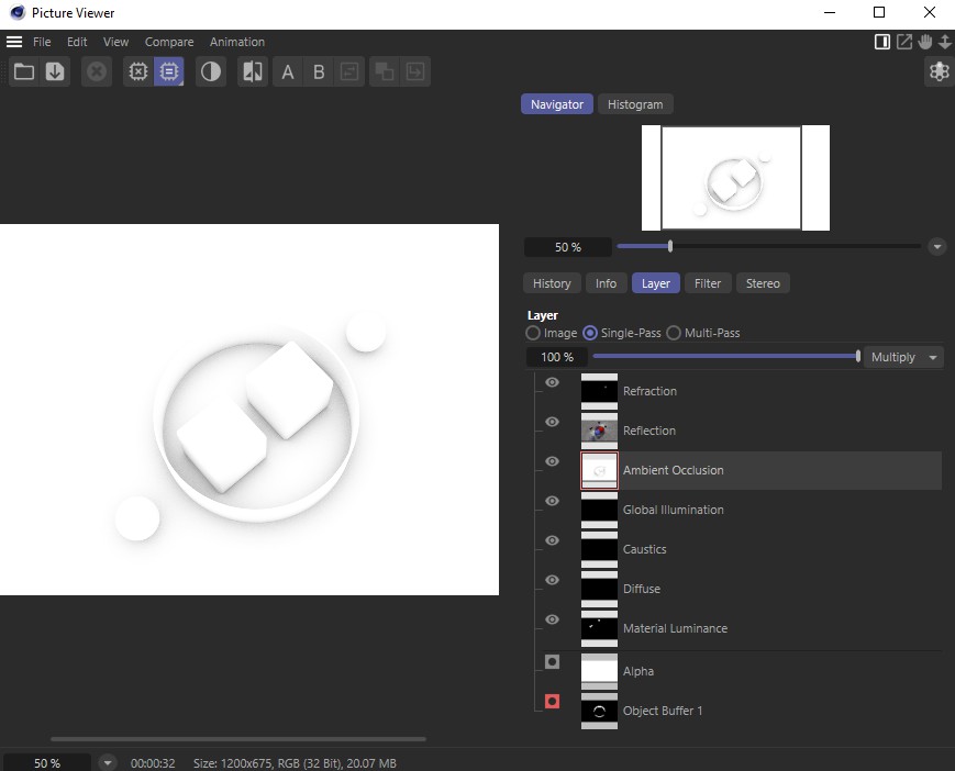
This tab displays the image selected in the History tab, including all passes and alpha channels. Depending on which of the following three options is enabled different image properties will be shown.
Image
Only the layer defined as "background" will be shown. This pass will always be shown and reflects the image rendered without a pass.
Single-Pass
If enabled you can click on individual passes to show them in the preview window. A pass can also be copied (![]() Copy) and pasted into Photoshop.
Copy) and pasted into Photoshop.
Individual Multi-Passes can also be isolated and saved. Note that a layer must be selected so it can be saved.
Multi-Pass
The image mode is switched to Multi-Pass mode, i.e., mix modes and mix strengths will be included in the passes shown. Individual passes can be hidden (and shown again) by clicking on the eye icon at their left.
As you can see, Multi-Passes can be combined here in several ways without having to switch to a compositing application.
These settings will be included in images that are saved via ![]() Save Image as... to a format that can handle Multi-Pass images.
Save Image as... to a format that can handle Multi-Pass images.
Blend Strength
Use this slider to adjust the strength with which a pass will be mixed with the underlying pass. A value of 0% reflects a non-existent pass and a value of 100% will cover the underlying pass completely.
Blend Mode
See Blend Modes.
Filter
The Filter tab's settings can be used to adjust the most common image properties. These modifications are of a temporary nature, which means that at first no real changes will be made to rendered or loaded images. Only when the images are saved with the Enable Filter option enabled will the Filter actually be applied to the images. This makes it possible, for example, to modify the contrast of an entire video (without affecting other properties such as the sound track).
Enable Filter
Enables or disables all Filter functions.
Tone Mapping
 Over-exposed areas on the left are corrected using Tone Mapping on the right.
Here you will find a simple tone mapping without additional settings as a supplement to the other filter settings. A more powerful tone mapping is available as a post effect Tone Mapping. However, the tone mapping there is saved permanently in the image while the tone mapping here in the Picture Viewer can be adjusted interactively before the image is saved.
The tone mapping here is primarily designed to "repair" over-exposed regions without changing the image too much overall (if you want to brighten darker regions, use Exposure. To make full use of Tone Mapping, we suggest you render in 32-bit. Not much can be done when rendering with 8-bit.
The Tone Mapping algorithm is known as Filmic (in case you want to research this online).
Tone Mapping can have a value from 0% (off) to 100%]] (maximum - as used on the right of the image above).
Saturation
Defines the amount of hue in a given color or in the colors of an image, i.e., how brilliant a color, or colors, will appear. A Saturation value of 0 will result in an image being reduced to grayscale values.
Brightness
Makes an image evenly brighter or darker.
Contrast
Higher Contrast values will darken dark regions and brighten bright regions of an image, which will amplify the differences between regions with different brightness values.
Lower Contrast values will lighten dark regions and darken lighter regions of an image, which will result in a optical "flattening" of the image.
Exposure
Exposure is used to adjust the brightness of HDR and also normal images.
Gamma
The Gamma value defines how the brightness values will be displayed (e.g., a bright pixel can be made much brighter or darkened). Basically the Gamma value is used to adjust brightness values.
Black Point/White Point
These values define the darkest and brightest points, respectively. If one of the values is modified the tonal value will be scaled accordingly.
Red, Green, Blue
Use these options to enable or disable each color channel.
Invert
Inverts the image’s color values. Black regions are made white and vice-versa. RGB images are inverted by subtracting the maximum pixel color value (i.e., from 255 for 8-bit color depth) for each channel (red, green, blue).
Reset Filter
Sets all modifications back to their original states, i.e., the original look of the image.
Gradient Curves
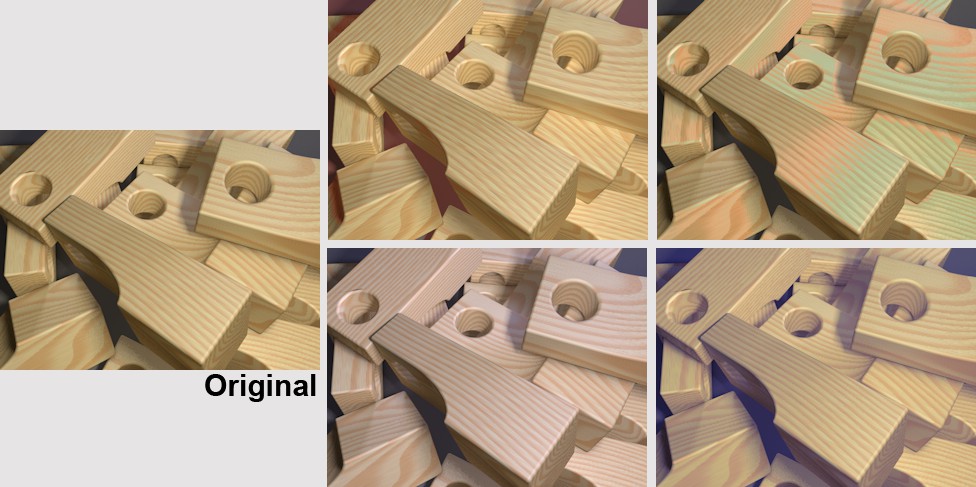 The gradient curves can be used to brighten, darken or color specific brightness regions.
The gradient curves can be used to precisely modify brightness and color regions of original image. For example, only the dark regions of an image can be brightened or brighter regions can be colored.
This can also be done for individual color channels using the separate red, green and blue gradient curves.
Grading Intensity
Here you can steplessly define the intensity of the Color Correction effect during rendering. A value of 0% disables the effect; a value of 100% maximizes the effect.
Min/Max
Use these settings to define the brightness region within which the gradient curves should unfold their effect. This is not important for 8-bit or 16-bit images since they have a range of 0 - 255 and 0 - 65535, respectively, and therefore use the default values of 0 and 1.
These settings are, however, relevant for use with HDR images. As you know, HDR images can contain an almost infinite amount of brightness. Using the Min and Max values you can more precisely restrict the brightness range within which the gradient curves should unfold their effect. Brightness values less than Min and larger than Max (values greater than 1000 can be entered) will remain constant (Attention: This means that all brighter regions will be omitted if the default Max value of 1 is used! The Max value must be adjusted manually). The gradient curve will then unfold its effect within this value range.
Curve
Use this curve (in addition to the RGB curves) to define the overall brightness. How the Curve works is explained below.
Red / Green / Blue
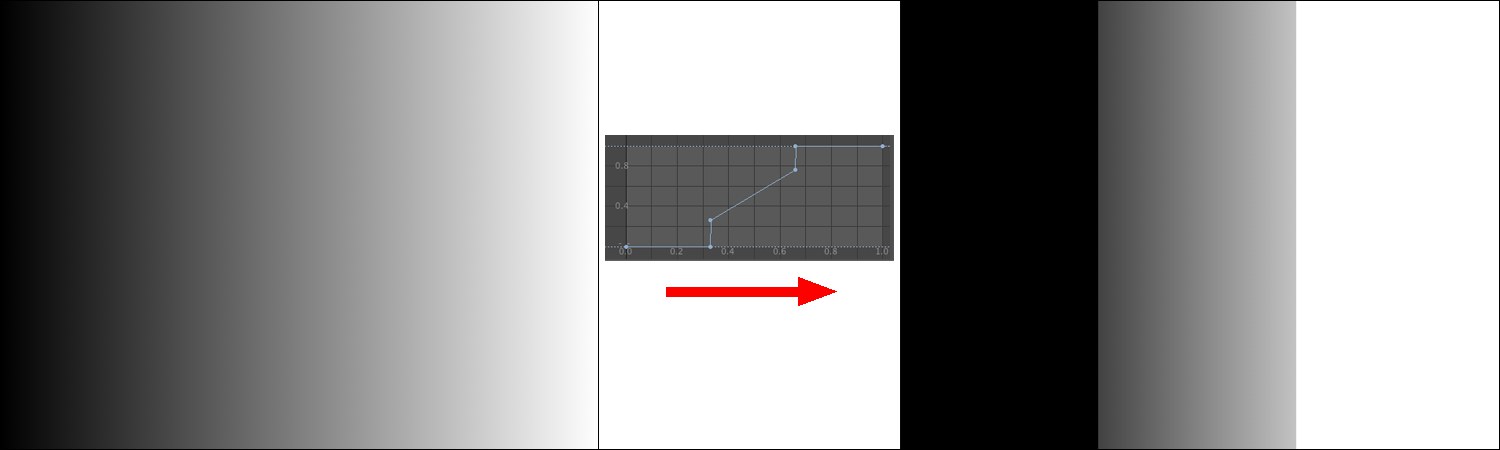 The gradient curve is applied to the linear grayscale at the left. The result is shown on the right.
A gradient curve defines where a new brightness value will be assigned along the X axis. This is easy to recognize in the image above. The Curve applies a brightness value of 0 to the first third, i.e., black. The second third has a linear gradient that assigns proportional brightness values to the region. The last third has a maximum value, which means it appears white.
This can also be done separately for each color channel, red, green, and blue. This makes it possible to color dark or bright regions only (the histogram in the Picture Viewer shows where which color dominates in the image):
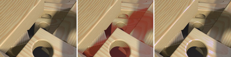 Dark regions in the center were colored red and bright regions at the right blue.
Create Post Effect
A Color Correction post effect will be created with which you can ensure that subsequently rendered images are rendered using the Filter settings defined here. This post effect will have exactly the same parameter settings as this Filter tab, thus saving you from having to subsequently filter the images in post production.
Save/Load Preset
Filter settings can be saved as presets in the Content Browser by pressing the Save Preset button. These can be called up at any time via the Load Preset button (and subsequently double-clicking on the preset).
Stereoscopy
In the Render Settings’ Stereoscopic menu, the following can be rendered for a stereoscopic image:
- Left camera view
- Right camera view
- The generated stereoscopic image
- Non-stereoscopic image
- Any number of additional camera views between the left and right camera views.
This is quite a number of views (for each frame of animation). Because the Picture Viewer can only display only 1 frame at a time you can define in this selection menu what exactly should be displayed. This selection menu only includes channels that can actually be rendered.
There is therefore a dependency between Calculate Stereoscopic Images and Non-Stereoscopic Image in the Render Settings.
Non-Stereoscopic Image
This is the image rendered from the normal camera view.
Merged Stereoscopic Image
The stereoscopic image rendered by Cinema 4D from the view of the left and right cameras, respectively.
Single Channel
The additionally available Channel value can be used to display the desired channel. In stereoscopy, either the left or the right channel will be displayed. In the Render Settings, however, you can define any number of channels for calculation during rendering.
Individual Channels and Merged Image
In this mode, the separately calculated images of the left and right eyes can be used to subsequently create a stereoscopic image (caution: this does not work with images subsequently loaded into the Picture Viewer).
Rendering has to be done using one of the "individual channels" in Calculate Stereoscopic Images mode.
The combined images (or individual channels) can then be saved via the Picture Viewer's Save command.
Mode
Anaglyph
This is the most well known method, which has been used in movie theaters since the 50s. An image’s color information is separated using 2-color glasses (previously red-green, today most commonly red-cyan). Advantage: simple, affordable glasses. Disadvantage: color range is in part very limited.
Interlaced
This method requires a monitor with a polarization filter and glasses with polarized glass. Since both images are coded into a single image (e.g., left eye all even, right eye all uneven lines), the resolution is halved. Advantage: affordable glasses, good color reproduction. Disadvantage: special monitor required, reduced resolution.
Side-by-Side
Left and right images are switched and squeezed into a normal image size. Some televisions use this technique for HD 3D because the transmission band width is the same as the HD band width. The terminal device must be able to decode these double images and display them sequentially (most commonly in combination with shutter glasses). Disadvantage: reduced resolution, expensive technology (special hardware required).
Additional Parallax (Pixel)
Moves the image halves by the defined value in pixels. This can be used to increase the stereoscopic effect.
Swap Left / Right
If enabled, the left and right image halves will be swapped.
System
The color of the stereoscopic color coding can be defined here when using the Anaglyph mode. Both colors should be the same as the lenses of the 3D anaglyph glasses you will be using. If your client does not supply you with color information, use Red-Cyan. This is the most commonly used color combination and can display numerous colors compared to the primary color combinations of red-green or red-blue.
You can use the Custom option to create your own color combination (however, it will then be difficult to find a matching pair of glasses…).
If Method is set to anything else but Full you will only be able to define the left eye color. The right eye color will automatically be set to the left eye’s complimentary color.
Left
Right
Here you can define the individual colors for the stereoscopic color coding (System must be set to Custom). The left color must be the same as the color of the left lens of the glasses.
Method
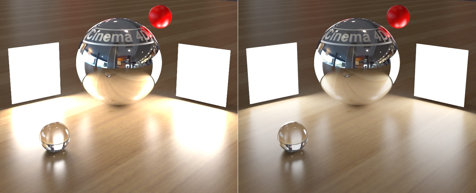
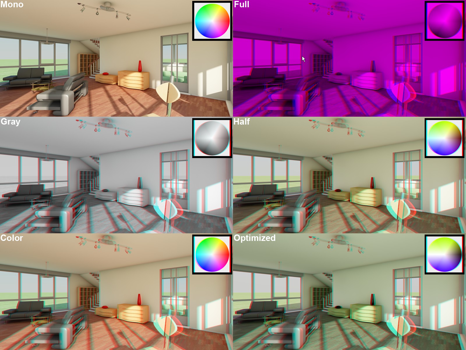 The different available methods (Full with anaglyph colors red-blue). Models by DOSCH Design.
Using this setting’s options you can affect the color of the stereoscopic image. A problem with the anaglyph technique is the color deviation of the original scene. Some colors cannot be displayed without straining the viewer’s eyes (red when using red-cyan coding). It is suggested that Optimized be used because it offers the least strenuous "viewing experience".
Red-Blue or Red-Green should be used when Method is set to Full…
The following list is closely arranged according to the quality that can be expected from anaglyph images. The list is arranged from worst to best:
The oldest (and lowest quality) method of anaglyph display due to the fact that the display is dark and monotone. This mode is designed for use with the Red-Blue or Red-Green anaglyph techniques.
The anaglyph image will appear as a gray-scale image through the glasses (not designed for use with red-blue or red-green). For brighter images use Full.
These modes allow only a limited color reproduction compared to the previously described options. Blue, green and yellow tones can be reproduced very well when the common red-cyan code is applied. If Color is selected, "retinal rivalry" can occur, i.e., red surfaces (red-cyan) will cause the left eye to pass on maximum color intensity to the brain and the right eye will only see "black". This is irritating and strenuous for the eyes (can be observed on the red vase in the image above). This effect can be minimized by selecting Half Color. However, red will then be darkened to such a degree that it can no longer be recognized as such.
This mode is similar to the Half Color mode but it offers better color reproduction and minimizes the retinal rivalry effect (see above).
Order
This mode defines whether or not both image parts should be arranged next to each other (horizontally or vertically).
Left mirror X, left mirror Y, right mirror X, right mirror Y
If Mode is set to Side-by-Side you are given the option of mirroring the image halves along the X or Y axes.
Type
If Mode is set to Interlaced, you can also define whether the coding should take place via offset lines (Horizontal) or columns (Vertical). Furthermore, there is an additional combination of both modes called Checkerboard.