Nodes Spline
Topic overview of this page
This group is comparable to a standard Node group, which can be used to combine any Nodes. The only difference is that a Geometry output is already available, e.g., to lead a newly-created spline geometry out of the group.
Above all, however, the Node Spline is designed to serve as a basis for the creation of asset capsules. Spline geometries created within a Node Spline can therefore also be used directly in the Object Manager. To do this, drag the Node Spline directly from the Asset Browser into the Object Manager. Double-clicking on the Node Spline icon in the Object Manager automatically opens the Node Editor in Capsule mode.
You can find more information on the use of this Node type in the following section, and on the subject of asset construction in general on this page.
If you want to process or create classic point or polygon geometry instead, select Node Mesh.
Additional inputs required for the group can be added via the Resource Editor or, for example, by right-clicking on the group and selecting Add Input. Further information on adding and managing these individual parameters to assets can be found on this page on the user interface.
These inputs are already available and are mainly useful if the Nodes Spline is used directly in the Object Manager:
The working principle
The Node automatically forwards all settings typical for splines to the Attribute Manager. So if you use the Node as a capsule directly in the Object Manager, a user can set the open/close status of the generated spline, its interpolation and also the generation of intermediate points directly in the Attribute Manager - without having to open the Node Editor. The settings configured within the asset are made available directly in the Attribute Manager as Auto settings, but can also be overwritten there individually if, for example, a spline that is actually closed is to be opened manually.
The following illustration demonstrates the principle. There, the Nodes Spline Capsule was first dragged from the Asset Browser into the Object Manager (shown in the illustration on the right). Double-click on it to display the content of the asset in the Capsule mode of the Node Editor, where the asset can now be filled with any number of nodes. In the example shown, two parametric splines are connected and opened at the end using the Set Closed Status Node before they are sent to the output of the Node as Geometry.
Exactly this shape is now generated and also displayed in the views, provided that the Auto settings for Type and Close Spline are active in the Attribute Manager (see middle section of the following illustration). The Close Spline status and also the Type of spline can also be overwritten there in a different way to the configuration within the Node Editor.
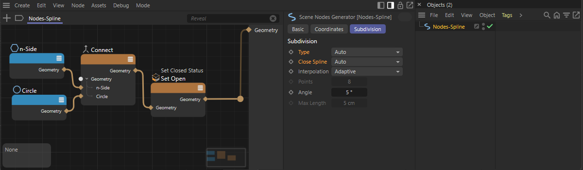 The spline created in the Nodes Spline asset is used the same way in the Object Manager as well, because of its Auto settings for the Type and the Close Spline options However, these properties can also be overwritten individually in the Subdivision settings.
Processing child object splines in the Object Manager
In the example above, primitive spline objects based on nodes were used directly within the Nodes Spline. This has the advantage that you can work directly with the available spline functions of the node environment. However, situations are also conceivable in which, for example, you want to leave it up to the user to decide which splines should be processed by the asset. You can use User Data to access the child-objects of the asset. This page informs you about all the options for using custom data on an asset. Let's look at another simple example.
To do this, open the Nodes category in the Asset Browser and find the entry for Nodes > Asset Construction in the left-hand category list. You will find the entry for the Nodes Spline there, which you can drag directly into the Object Manager with the mouse. Double-click on the Nodes Spline element in the Object Manager to display the content of the Nodes Spline asset in the Node Editor.
The node set-up of this asset should now work with two splines, which a user must group below the Nodes Spline in the Object Manager. The following illustration shows this on the left-hand side.
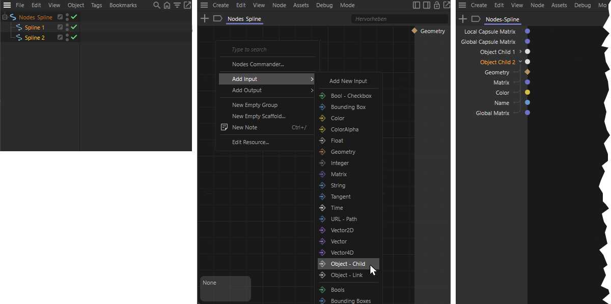 Spline objects grouped as childs under the Nodes Spline can be read via manually created Object - Child inputs in the Nodes Editor.
So that we can now access these two splines under the Nodes Spline in the Node Editor, two corresponding inputs must also be created there.
To do this, right-click in the Node Editor and select Add input > Object - Child. This will give you a new input on the left-hand side of the Node Editor, which you can use to access the topmost object under the Nodes Spline in the Object Manager (see middle illustration in the figure above). Double-click on the name of this input to rename it individually in the Node Editor.
Repeat these steps again to add a second input in the Node Editor. As can also be seen on the right-hand side of the figure above, these inputs can also be expanded in order to directly access all important properties of the two child objects, such as their Geometry or Matrix.
Please note that the information at the Geometry ports for splines is generally only provided as Line geometry. It is also possible that the user accidentally uses polygon objects as children instead of splines. You should therefore carry out a few checks so that you can be sure that you are working with the correct object types within the asset.
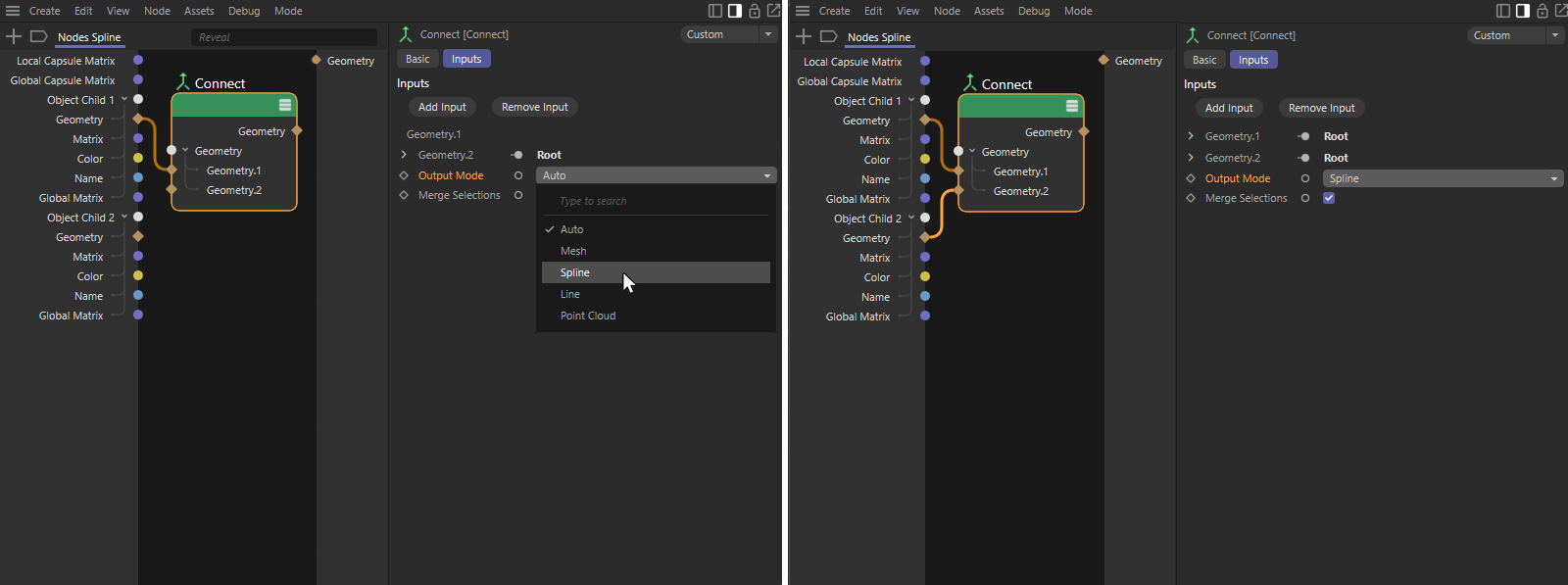 Convert Line Geometry to Spline Geometry with a Connect node. Shown on the left for a single geometry, demonstrated on the right for combining several line geometries into a spline geometry with several segments.
As can be seen in the figure above, a Connect node can be used to convert the line geometry into a spline geometry (see Output Mode setting for this node). If you require all child objects as separate geometry within the node set-up, simply route each Geometry input to a separate Connect node, as shown in the example on the left-hand side of the illustration for the first child object.
Alternatively, several Geometry inputs can also be configured on the Connect node, as shown in the illustration on the right. In this case, all connected line geometries become individual segments on a spline geometry. The first child object therefore becomes segment 0 and the second becomes segment 1 on the connected spline.
When processing geometry, it should generally be noted that its points and tangents, for example, are only ever passed on in local coordinates. If you are planning a spline output based on the child splines in the Object Manager, for example, which also moves accordingly when the spline objects are moved or rotated, the line geometries in the node set-up must be converted globally. To do this, we use Transform Geometry nodes, as shown in the following illustration.
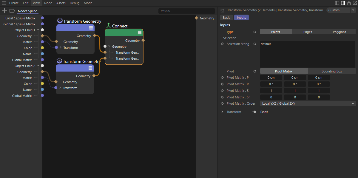 Global conversion of geometry
If you combine these nodes with the Matrix of the read geometry, you will receive a globally converted geometry at the Geometry outputs of the Transform nodes. Just make sure that the Type setting on the Transform Geometry node is set to Points, as we are dealing with a line geometry that does not contain any edges or polygons.
But stop! How do we actually know that the user has done everything correctly and that two spline objects, as required by our asset, have actually been grouped as childs in the Object Manager? Well, of course we can't know that and should therefore check it in the node environment before we work with these geometries.
Checking child objects
A Geometry Info node can be used to check whether an object required in the circuit is actually available and also has the required type. This provides various outputs with bool signals, which can be used to query whether a geometry exists at all (Has Value) and whether the geometry is of type line (Is Line), for example. In our example, we compare the two outputs mentioned with a Boolean Operator in AND mode. This node then only supplies a positive bool signal if both inputs are also positive, i.e., both a geometry is present and their type is Line. As two line geometries are required for out node calculations, we carry out the same check for the second Geometry input. The results of both checks can be summarized again with an AND check, which then only returns a positive result (or TRUE or 1) if all criteria apply to both child objects.
As can be seen in the following illustration, this could be used, for example, as an Index for a Switch node to provide either the geometry of the two inputs or, for example, a default geometry (here a Circle with the Ring option activated to obtain two segments) for further geometry calculations or the output.
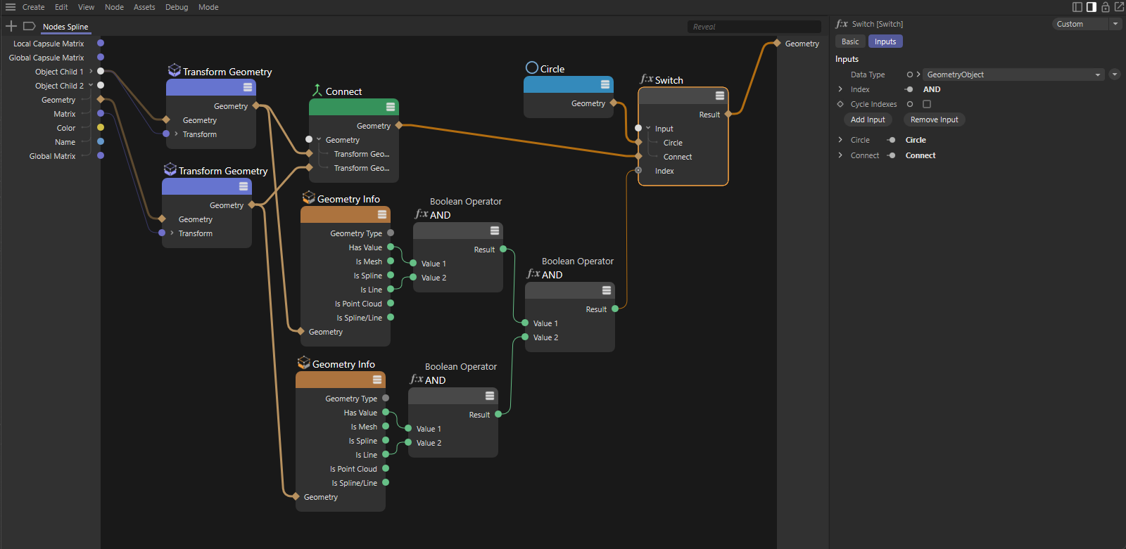 Check the assigned objects and output an alternative geometry in the event that no compatible geometry is available.