The Node Editor
![]()
Contents of this page
- General
- The Node Editor
- Navigation in the Node Editor
- Node Editor header
- The Navigator
- The Info Area
- The input and output group areas
- Other Node Editor components
- Features of the Scene Node Editor
- The modes of the Node Editor
- Working with Nodes
The Node Editor has different modes - depending on which Node types are used - that switch automatically. By default, the Node Editor opens in Scene mode, where you can create Node-based setups that generate custom geometry, for example. Collaboration between classic objects and Node-based functions is also possible in this mode, but requires small detours via additional Nodes.
If you activate a Node-based material, the Node Editor automatically switches to Material mode, in which only the Nodes that can be used for materials can be used. Finally, the Node Editor's Capsule mode automatically activates when you select an Asset Construction group. These special Nodes can be used directly in the Object Manager, where they can also be grouped directly with classic objects for example. You can find an example here.
You will find hints here and there in the following text that this or that function only works in certain modes.
General
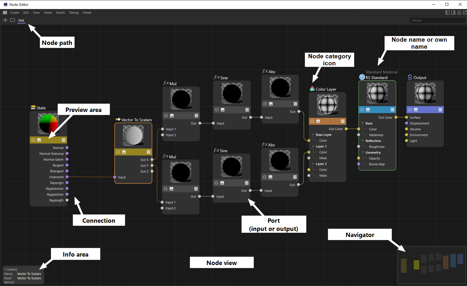 Sample representation of the Node Editor in Material mode.
For faster access to all Assets, Capsules and Nodes, the Asset Browser can also be displayed on the left side of the Node Editor. In addition, the Attribute Manager can also be displayed on the right edge of the Node Editor to allow the configuration of selected Nodes directly in the Node Editor area. This is especially helpful when using a full-screen or floating Node Editor window, and when configuring Node materials to shorten mouse travel when editing values. The icons for showing and hiding the Asset Browser and Attribute Manager can be found in the upper right corner of the Node Editor.
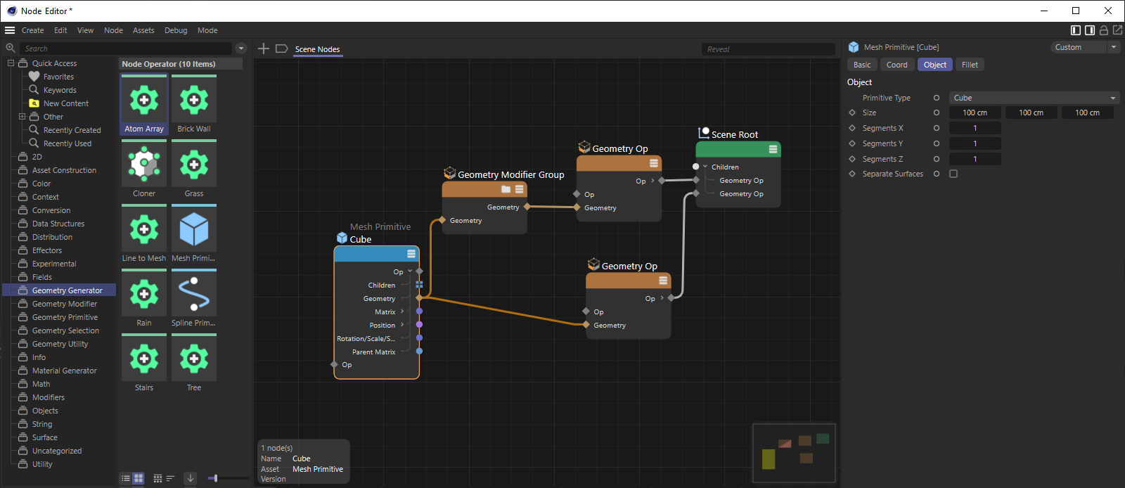 The Asset Browser and Attribute Manager can be displayed at the sides of the Node Editor.
The following applies to the Node Editor ("Material" mode):
The Node Editor is the central instance when creating and editing material Nodes (hereafter simply referred to as "Nodes"). To create and edit Nodes, a Node-based material must be selected. The Node Editor always displays the currently selected Node material.
It should be noted at the outset that Nodes are a not entirely straightforward subject and can only be used in their full breadth with a good degree of knowledge of shading and rendering techniques in general. However, many things are also quite simple, for example, by using one of the pre-made materials, such as the Redshift Standard Material, which you can operate almost as easily as a conventional material .
The general data flow is always from left to right. On the far right, for Redshift Materials, everything always flows into an Output Node (without this, there is no functioning material; there is always only one Output Node per material).
To open the Node Editor, you have several options:
- by double-clicking on the Node Material in the Material Manager.
- by clicking the Node Editor button of a Node Material ("Base" tab in the Attribute Manager).
A description of all Redshift Material Nodes can be found here. You can also read the description of the nodes in the slightly older Cinema 4D material system here.
The following applies to the Node Editor ('Scene' mode):
The content of the Node Editor is not assigned to a special element (like the material Node Editor is assigned to a Node material), but is embedded in the scene itself. Therefore, the last, outputting Node with its output 'Op Output' must always be connected to the Scene Node that is already present by default, otherwise no geometry will be generated.
Note that the Scene Node Editor is intended more for advanced users and can be used in its full breadth only with a good level of 3D knowledge and technical savvy. For a brief introduction, see Scene Nodes Introduction.
You open the Scene Node Editor by calling the "Node Editor" command (In the main menu under "Window").
Also note some special functionalities of the Scene Node Editor described here further down the page.
As was the case with the Node Materials at the time, the Scene Node Editor was also equipped with many additional, specific Nodes. Some Nodes (such as the Math Nodes) are available as a feature in both the Material Node Editor and the Scene Node Editor. You can find all Scene Nodes described under The Individual Assets.
For the display of the geometry generated by the Scene Node Editor there are some special view settings in the Project Settings (see Nodes).
The following applies to the Node Editor ("Capsule" mode):
This mode is even more special than the previous two modes, because it is automatically activated when a Node is dragged or selected from the Asset Construction Nodes group, for example, to the Object Manager. These Nodes form the basis for the creation of Asset Capsules, with which you can, for example, create your own objects, selection methods, deformers or modeling commands with Nodes and, among other things, combine them directly in the Object Manager with classic objects. Since these Nodes function like a group, the Node Editor automatically displays the contents of the selected Asset Construction Node. However, if a conversion to an Asset has already been performed, the Capsule mode is enabled, but the content of the Asset can no longer be displayed directly in the Node Editor. To do this, the Asset must first be converted back to a group, for example.
The content of the Node Editor is not assigned to a special element (like the material Node Editor is assigned to a Node material), but is embedded in the scene itself. Therefore the last, outputting node with its output 'Op Output' must always be connected to the Scene Node, otherwise no geometry will be generated.
The Node View
Navigation:
You can navigate in the Node view as you are used to from the Editor and other managers, using the following hotkeys (see also commands in the 'View' menu):
- Move: Press one of the following keys and drag the mouse: MMT, 1 + LMT, Alt + MMT or click and drag in the Navigator. If Touchscreen is activated in the Program Preferences ("Input Devices" tab), the following will also work: Mouse wheel up/down (vertical shifting) and Shift + mouse wheel (horizontal shifting)
- Zoom: Press one of the following keys and drag the mouse: Alt + RMT, 2 + LMT, mouse scroll wheel (if touch screen is enabled: Ctrl + mouse scroll wheel)
- Show all or selected: H or S.
If you have shown the Navigator area at the bottom right of the Node Editor (this can be shown via 'Show Navigator' in the 'View' menu, among other things), this can also be used for navigation. To do this, simply click on the location within the Navigator that you want to be centered in the Node Editor.
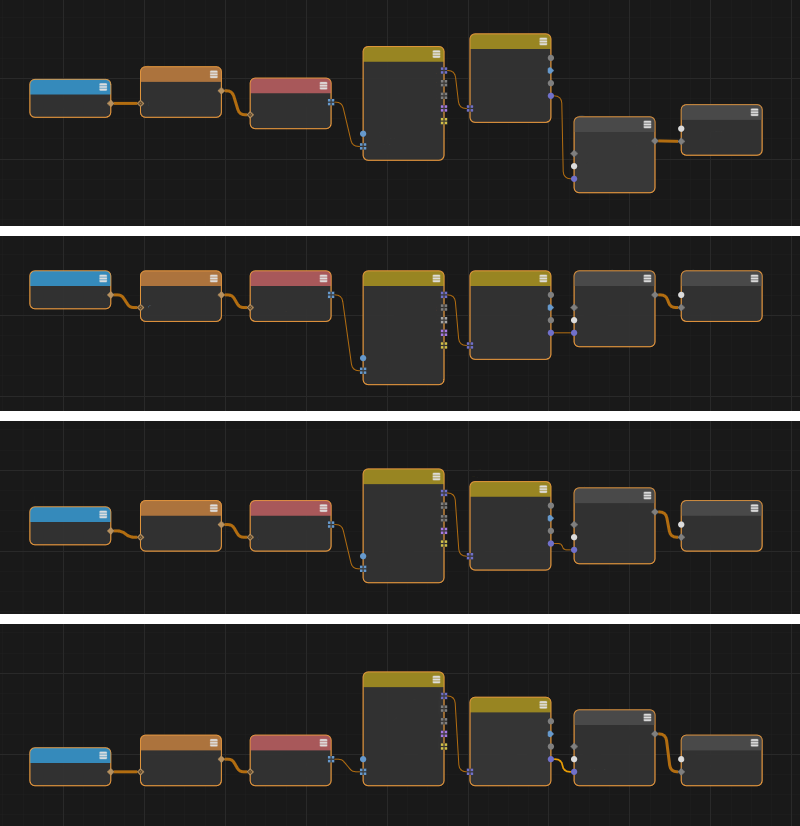
The Node Editor itself offers a similar simplification of the Node representation when zooming out from a Node setup. In the process, the details of the Nodes and also their labels are continuously reduced and finally, in the case of strong reduction, also completely hidden. Thus, even with scaled-down setups, it is still easy to see which Nodes were used and how they are connected to each other. The following sequence of images shows this effect.
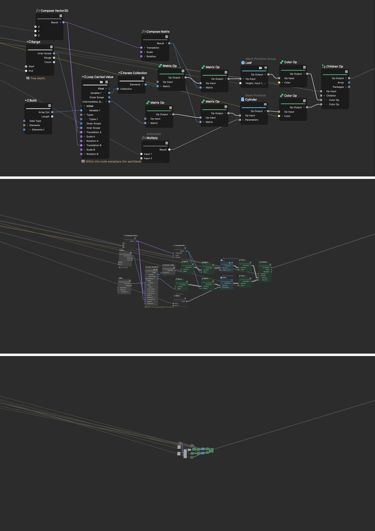 This sequence of images shows, from top to bottom, the automatic reduction of details on zoomed-out Node-based setups.
Creating Nodes
For example, you can create Nodes as follows (by dragging and dropping, double-clicking, etc.):
- directly from the Asset Browser:
- Drag a Node from the Asset Browser to the Node Editor.
- Click the Add Nodes button (plus icon in the upper left corner of the Node Editor) or
- Double-click an empty space in the Node Editor (alternative: C key), and the Asset Browser's Asset list opens in each case. - Dragging a bitmap file from the Finder or Explorer or the Asset Browser directly into the Material Node Editor automatically creates a Texture Node (for a Redshift material) or an Image Node (for a Cinema 4D Node Material).
- Existing Nodes in the Node Editor can be duplicated by dragging and dropping them while holding down the Ctrl key, as is usual with objects in the Object Manager. If the key combination Ctrl+Shift is held while dragging and dropping a Node, the connections of the original are also retained at the Node duplicate.
Node Presets
The preset system allows you to save settings, e.g. for tags, objects, color gradients, brush tips or even Nodes, so that you can quickly access them again at any time. Presets can be set as default to be called automatically when an object or e.g. Node is called. Otherwise, these presets are managed in the Asset Browser and can be viewed there at any time. Further explanation of the preset system can be found here.
 As is known from objects, the settings of Nodes can also be managed via presets. This allows quick access to proven settings, e.g. for different materials, especially when using Material Nodes.
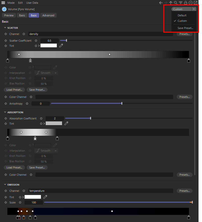
Especially when configuring Redshift Materials, you will notice that identical Nodes are used again and again, but with customized settings. Think of the Pyro Volume Node, for example, which controls the display of flames, explosions or smoke. If you have found settings there that you like, e.g. for displaying a candle flame, simply use the Preset menu in the upper right corner of the Attribute Manager to have a new preset saved there. Note that this menu is not available in the Attribute Manager of the Node Editor, but only in the Attribute Manager of the Cinema 4D layout.
The following options are available in the menu:
- Presets: In the upper part of the menu you will find the already saved presets for direct recall. If no presets have been saved for the currently selected element, this menu area is empty.
- Preset: Each node, object, and tag has an invariant preset that is automatically invoked when a Node is created, for example, if no Custom presets have been activated. If you have made changes to the settings that you want to undo, select this menu item to return to the Default settings.
- Custom: As soon as you change settings, e.g. configure a Node differently from the Default settings, this is displayed as a 'Custom' preset. If desired, these settings can be saved with the following menu item.
- Save Preset...: This opens a save dialog that allows you to assign a name to the settings, among other things. After saving, you will find this name in the Preset menu for quick recall of the settings. In addition, by default, these settings are stored in the Preferences database within the Asset Browser.
By checking the As Preset option, the saved Preset will be used as the default and automatically applied when the respective Node, tag or object is called up.
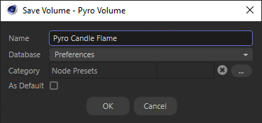 Dialog for saving presets
All presets are stored in the Asset Browser and can be viewed there after calling up the Preset tab. Here you can also delete or rename unnecessary presets. You can find corresponding functions in the context menu that opens after right-clicking on a preset. In addition, presets can still be defined as defaults afterwards, in case you forget to activate that option when saving a preset. To do this, move the mouse pointer over the icon of a preset in the right pane of the Asset Browser. Two additional icons appear on the logo:
- Heart: By activating the heart icon, you can mark as many presets as you like as your favorites. This feature can be used, for example, to filter search results in the Asset Browser or generally to find preferred settings more quickly.
- Crown: This is used to mark a preset as the default, which is then automatically called up and applied when a Node, tag or object is called up, for example. Therefore, due to this property, only one preset can be marked with a crown for the respective element at a time
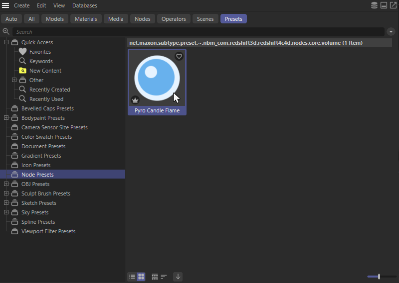 Listing of saved presets in the Asset Browser. Additional options for marking as Favorite or Default appear when the mouse is placed over the icon of a preset.
Moving Nodes
Nodes can be grabbed and moved with the mouse at any time. Several selected Nodes are moved together. If you approach the edges of the Node view while dragging Nodes, the Node view will start scrolling. To select the Nodes, you can draw a selection frame by holding down the left mouse button or simply click on a Node. This can also be combined with the Shift key to select multiple Nodes in succession by clicking on them. If the Ctrl key is held down while clicking on an already selected Node, the Node can be deselected again.
Connecting Nodes and creating Ports
In order for data to flow from one node to the next, they must be connected to each other. Node outputs (right-hand node side) of one node can be linked to node inputs (left-hand node side) of another node. For this:
- Click once on the output port and once on the input port (or vice versa). If the data types processed by these ports are compatible, a connection is automatically established after the second click. This is very convenient for Nodes that are far apart.
or
- Hold down the left mouse button and draw a direct line between the ports to be connected and release the mouse button when you reach the target port. If you come close to the border of the Node Editor while dragging the connection, you can also scroll through larger setups until the desired node and its port become visible.
or
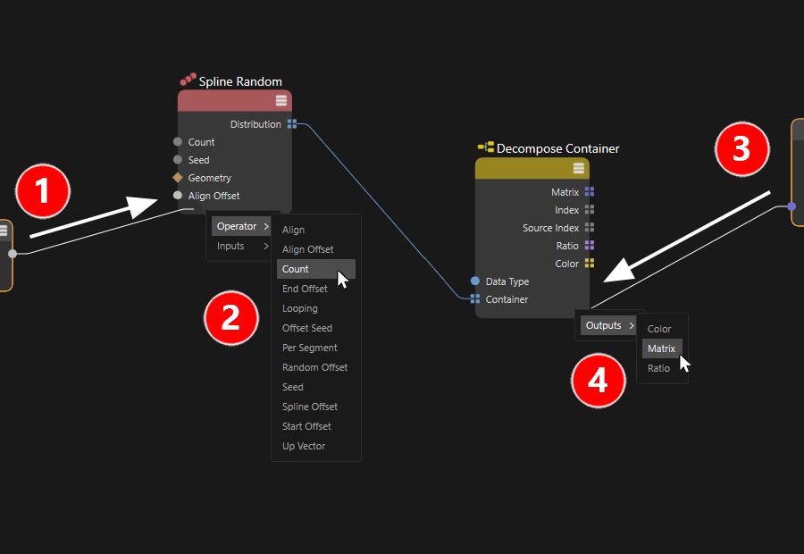
- If the required input or output is not yet available on a node, you can also drop the connection line of another node port within the node to be connected. A context menu then appears in which the desired port can be selected from all the inputs or outputs compatible with the connection that has been dragged. If only one possible input or output is available for the connection drawn to a node, the connection is created automatically.
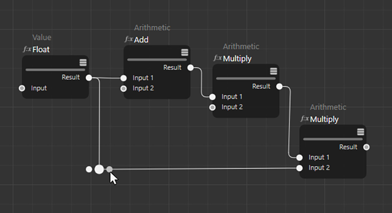
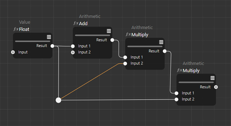
- If there is already a connection to a port that should also be routed to other ports, this connection can be directly duplicated and routed to a new port by holding Ctrl while dragging with the mouse. This can be especially handy if the output port of the existing connection is outside the area of the setup currently under consideration. The following figure exemplifies this type of connection.
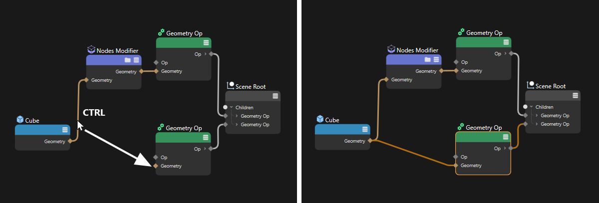 An existing connection is duplicated by dragging it with the Ctrl key combination and can thus also be routed to other ports.
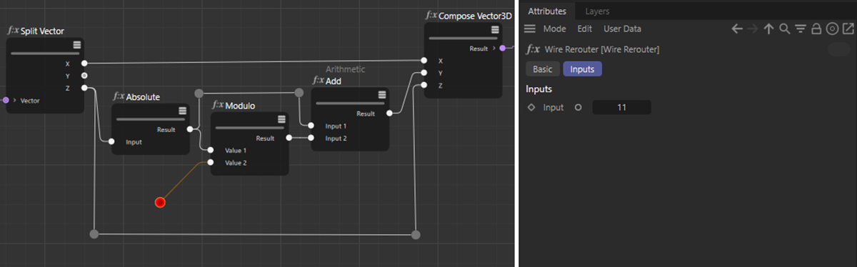
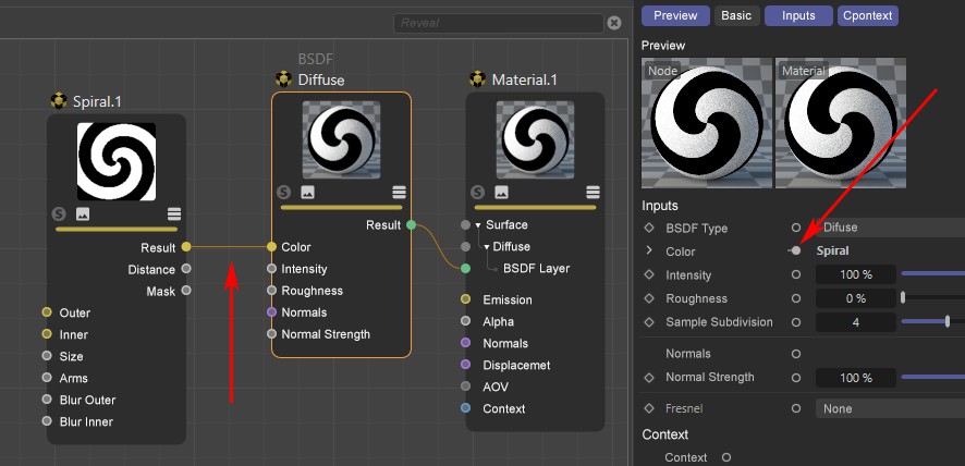
- In the Attribute Manager, you will find a circular connection icon for almost all parameters that can be used as inputs on the node (see red marking in the following illustration).
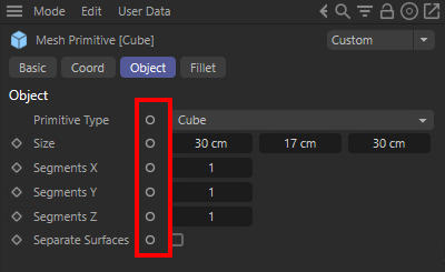 Node parameters that can be used as input ports have a special connection icon in the Attribute Manager (marked red here).
Left-clicking on these connection icons opens a context menu. With Connect Node you get a list of all Nodes. There, select the new Node to be created and connected. The Existing Nodes subgroup lists only the nodes that already exist. You can also reach the same command by right-clicking on a port. If you right-click an output port, only the Nodes already present in your setup are offered for connection under Connect Node.
- The connection icon of a node parameter just mentioned in the Attribute Manager can also be used to create an input for this value on the node. To do this, simply Ctrl-left-click on the circular connection icon.
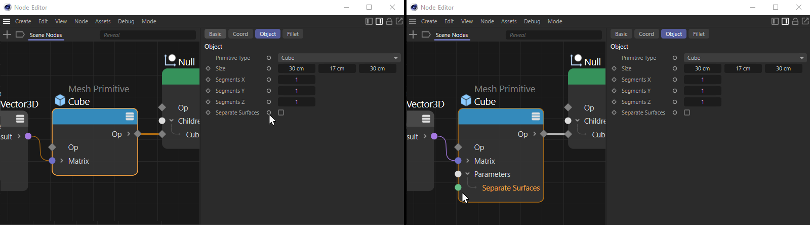 The left image shows at the mouse pointer in the Attribute Manager one of the circular connection icons behind one of the Node parameters. Ctrl-click on it to automatically add the corresponding input port to the Node (if it is not already visible).
When connecting ports, the following also applies:
- As long as you are in connection mode (first port to be connected has already been clicked), this process can be canceled at any time by pressing Esc.
- Existing connections can be "bent" to other ports (even of other Nodes) at the port or the connection itself by holding down the Shift key.
- A connection created by mistake can be removed by double-clicking on it.
- Only ports whose data types are compatible with each other can be connected.
Cinema 4D does try to convert different types of data where possible, but this is not always possible. Cinema 4D shows you if the connection is possible: as long as you hover over the second port to be connected, a stop icon appears if no conversion between the data types of the two ports is possible.
Optimize Connections
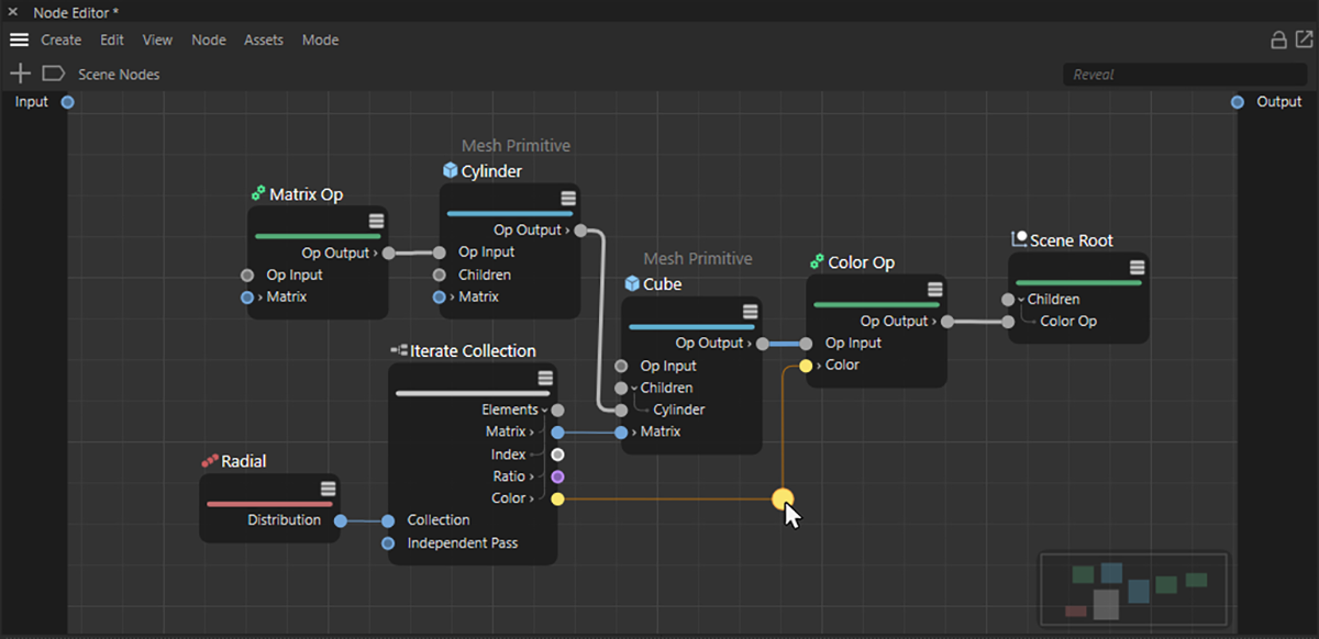
When connecting ports, connection lines may intersect or pass through other nodes. This can negatively affect the readability of a Node-based setup. We can therefore also run connections via a so-called Wire Rerouters. The advantage can be seen in the following pictures.
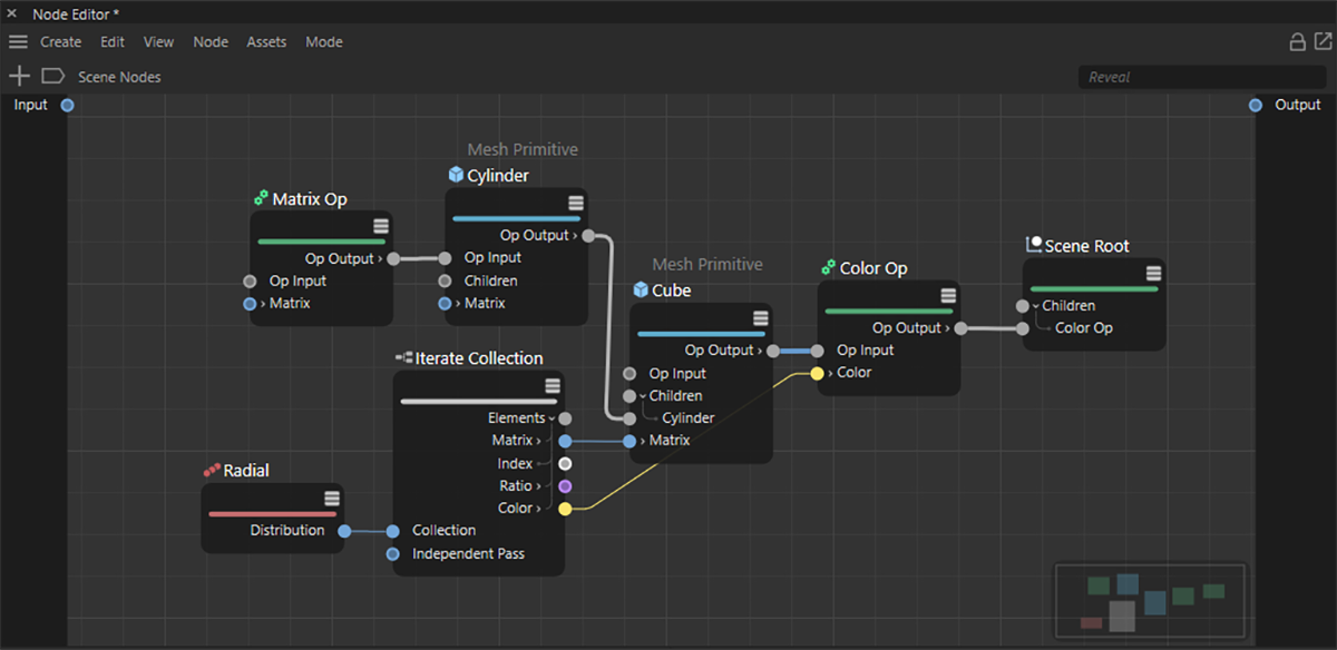 In this example, the connection for the color value is partially obscured by a Node.
To improve the readability and clarity of the setup, connecting lines can be additionally subdivided. Similar to adding a new point to a linear spline, this allows the course of the connecting wire to be changed individually. To do this, simply Shift+Ctrl-left-click on the connecting line that you would like to change. In this way, any number of Rerouter points can be created along a connecting line. Wire Rerouters that are no longer needed can be deleted by clicking and pressing the Delete key without removing the connecting line.
 If the mouse pointer is placed on a connection with the Shift and Ctrl keys held down additionally, a redirection point appears on the connection line and can be moved there freely. Alternatively, simply Shift+Ctrl-left-click on a link line to directly set a Wire Rerouter.
A Wire Rerouter can be grabbed and moved directly with the mouse. The course of the connector line can be modified freely. For even more complex courses, additional Rerouters can be added on the same connection wire.
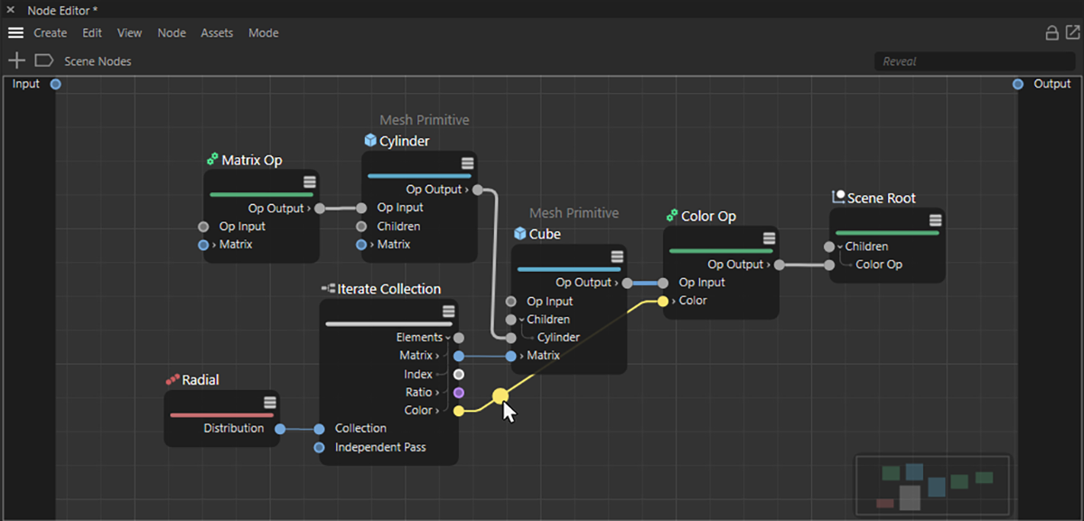
 The Rerouter can be moved directly with the mouse to influence the course of the connecting line individually. In this example, this can avoid the overlap between the connection and the Node.
This option makes especially horizontally running Node setups clearer, as the coming pictures show.
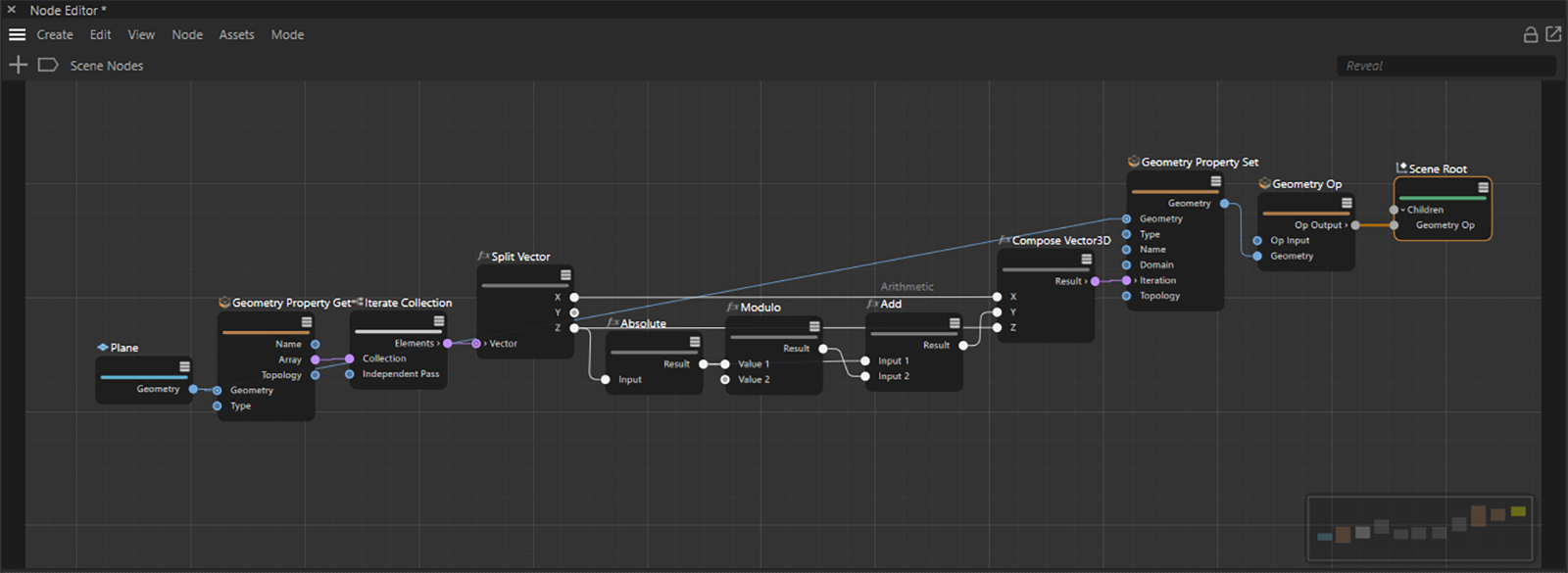 The more complex Node setups become, the more masking between Nodes and connecting lines can occur. In this example, for example, it is not possible to see directly how the connections between the three mathematical Nodes in the middle of the setup run.
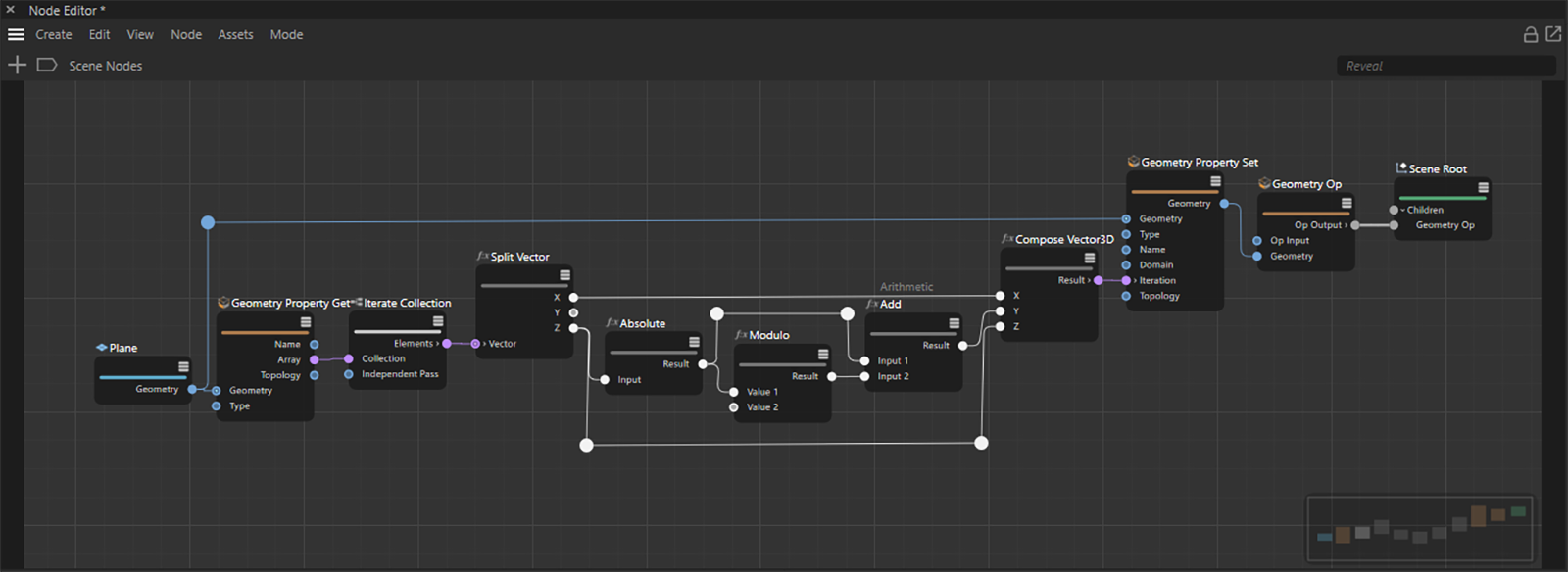 The use of Wire Rerouters makes the setup clearer.
The Rerouters can be used not only to form the connecting lines, but also provide the data themselves, which are transmitted via the connecting line. They can therefore also be used as branch points of a connection, as the following example shows.
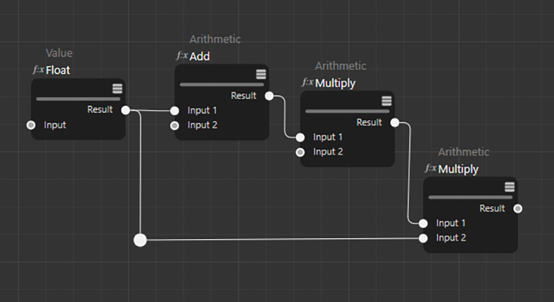 Here, a Rerouter was used to improve the clarity of the Node graph.
If the cursor is moved in the vicinity of a Wire Rerouter, two port points will be displayed, from which a new connection can be dragged when clicked upon.
 At a Rerouter, additional ports become visible when the mouse approaches.
By linking the ports on a Wire Rerouter to other Node inputs, the Rerouter can be used like an output port.
 A Rerouter can be used like a port and use additional connection lines.
Wire Rerouters can be duplicated via Ctrl-Drag&Drop or also dragged directly from the Utility category of the Nodes in the Asset Browser into the Node Editor and thus created independently of an already existing connection. If a connecting line is then drawn from such an independent Rerouter to an input port, the freestanding Wire Rerouter can be used like a Value Node. So you can then select the Rerouter by clicking on it and use the Attribute Manager to enter a value that should then be forwarded to the connected Nodes.
This function can also be very helpful for creating order in a Node graph, because Rerouters also have Basic settings in the Attribute Manager, which can be used, for example, to store a comment on a value used.
 An already existing Wire Rerouter can be duplicated e.g. via Ctrl-Drag&Drop and placed anywhere in the Node Editor. If such a free Wire Rerouter is then connected to a Node input, the Rerouter can be used like a Value Node to enter a value.
Use floating inputs and outputs
When you work in an Asset or group, there are inputs and outputs on the left and right, respectively, that allow the Asset or group to communicate with other Nodes or components outside. For Assets, such inputs can also be used, for example, to transmit individual user data to a Node setup.
With more extensive Node-based graphs, this can lead to long connections again, if, for example, Nodes at the right end of the graph still have to access the values from the group inputs. With Floating IO Nodes this problem can be solved easily, because any inputs and outputs to Assets or groups can thus also be placed directly as Nodes within the graph, i.e. where these values are needed.
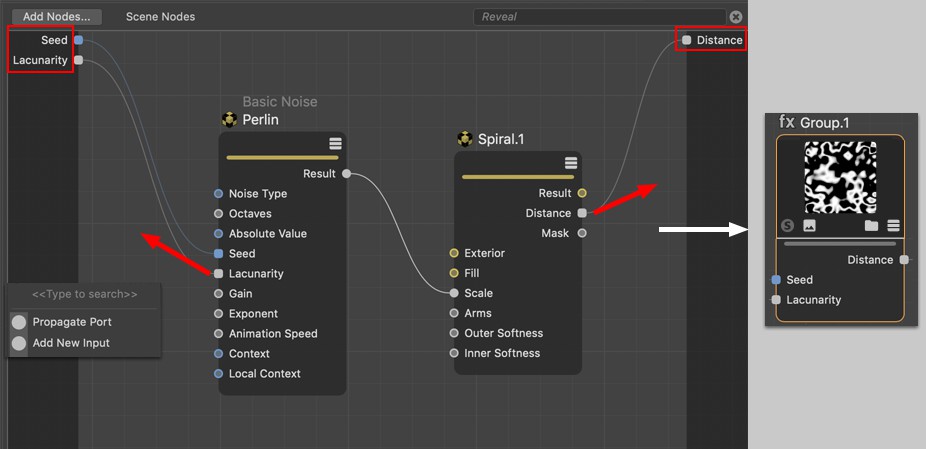
To do this, simply drag the name for instance of an input port from the left boundary of a group or Asset by dragging and dropping it into the graph. A new Node is automatically created, which now offers this input as a port. The following image shows an example of this.
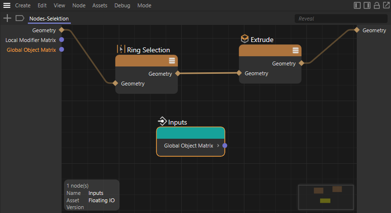
In the input area of a group or Asset (see the light gray area on the left edge of the Node Editor) there can be different input ports. If you want to read out the value of one of these inputs directly in the Node graph without having to make an extra connection to the corresponding input port, Floating IO Nodes can be used for this purpose. In this example above, such a Node was created for the Asset's Global Object Matrix input and placed in the lower part of the graph. It is also possible to use several Floating IO Nodes of the same or different input ports in the Node graph without any problems.
The same principle works for the outputs. Dragging the corresponding port names from the right column (output side of the group or Asset) into the graph also creates Floating IO Nodes, which now have corresponding inputs. The only difference to the inputs is that there may only be one Floating IO Node per group output. Otherwise, there would be the danger that several, possibly different values are sent to the same output, which of course must not be the case.
Selecting Nodes
You can select Nodes by rectangle selection (simply draw a rectangle in the Node Editor starting in the empty space by holding the left mouse button ) or by clicking on a Node. As always, the Shift (add to selection) and Ctrl (remove from selection) keys work. In the Edit menu you will find some more selection commands (like Select Connected).
Selected Nodes display their settings in the Attribute Manager and the Info pane. This also applies to Wire Rerouters.
Deleting Nodes
Selected Nodes can be deleted by pressing the Backspace or Delete key. This also works with Wire Rerouters.
Node Editor header

You will find the following elements at the very top of the Node View (from left to right):
- Add Nodes: Click on the plus icon to open the Asset Browser's Asset list. A double-click in the Node Editor also opens an Asset Browser directly on the mouse pointer. Alternatively, by clicking the left icon in the group of four icons in the upper right corner of the Node Editor, the Asset Browser can also be permanently displayed on the left edge of the Node Editor. In this sectionyou will learn more about the function of these icons.
- Node search path:Clicking on the bookmark icon opens a separate window with the possibility to enter a Node Path. This is especially helpful when using the so-called Heat Map function to navigate directly to a specific Node or group in complex Node graphs. For more on using the Heat Map function to analyze a Node graph, see the section on Debug Functions.
- Node path: In addition to the bookmark icon, the hierarchy tree of the node graph already viewed is displayed here. The term 'Scene Nodes' stands for the top level. If you are currently working on Material Nodes, read the name of the material there instead. In the Capsule mode of the Node Editor, the name of the displayed Asset Construction Node can be read here.
If you group Nodes together and then open one of these groups, you use it to navigate down one hierarchy level. Accordingly, the Node Path is now displayed expanded by the name of the opened Node group. By clicking on the corresponding part of the Node Path, you can then navigate back to higher hierarchy levels. The principle thus corresponds to the path that you can also display in the Object Manager and use to navigate in hierarchies.
The displayed node path always shows the lowest hierarchy levels that you have viewed by opening groups. In this way, for example, it is possible to quickly switch back and forth between, for example, the top Node level and the Nodes in a deeper subgroup by simply clicking on the corresponding section in the displayed path. The hierarchy level currently displayed in the node editor is also highlighted with a blue underline. - Highlight: Specify here a string that will act on the currently displayed Nodes. Nodes whose names contain this string are visually highlighted by making others semi-transparent. A handy thing to quickly find specific Nodes among dozens.
- Additional Asset Browsers and Attribute Managers can be displayed on the side edges of the Node Editor using the icons in the top right-hand corner of the Editor's header. In addition, the current view of the editor can be locked via the shackle lock icon. The fourth icon calls an additional instance of the Node Editor. You can also read more about these four icons here.
The Navigator
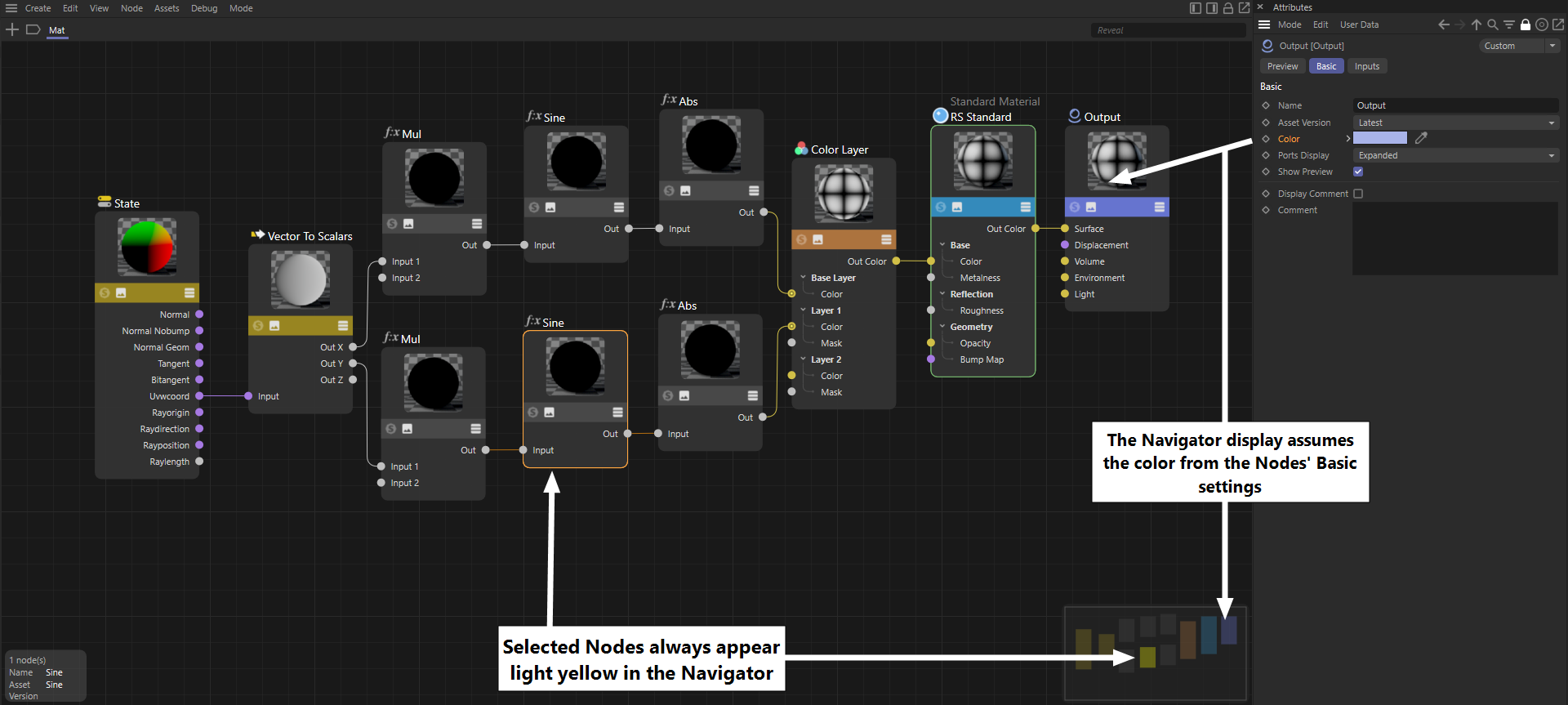
You can find the Navigator at the bottom right of the Node View. It is a scaled-down version of the entire, current node graph and is used for orientation and quick navigation in complex node setups. The light gray rectangle shows the visible section of the Node View. You can move this section by clicking in the Navigator and dragging with the mouse button pressed. This allows quick navigation to other areas.
By simply clicking in the Navigator, the corresponding area is displayed centered in the Node Editor.
The following Nodes are displayed in particular:
- Colored Nodes ('Basic' tab) are displayed with identical color.
- Selected nodes are displayed in light yellow.
- Group Nodes are provided with a diagonal.
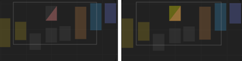 Group Nodes are always displayed in two colors, divided diagonally. On the top left, the Node's own color is used, and on the bottom right, a reddish hue, as shown in the left half of the figure above. If the group is selected, its representation in the Navigator will get a yellow color, as it can be seen on the right.
The input and output group areas
You will find 2 dark stripes on the left ("Input") and right ("Output") side of the Node View (if ports leading to the outside have already been created). You can lead out connections/ports by dropping a new connection in an empty area of the Node View.
This makes little sense for individual Nodes, but if you nest groups, for example, you can use this to create a port that appears as a group port (as shown below in the figure on the right). I.e., even with a group within a group, you can feed a particular Node port at the lowest level from the outside (or feed it as an output to the outside).
 Node ports in groups can be routed to the outside.
When dropping a connection in the empty space, a small menu opens (see Figure below left) with the following entries:
- Add New Input, round port: here the connection can be deleted without deleting the input. An input can be reconnected from the inside.
- Add New Output, square port: if you delete the connection here, the port will also be deleted. Ports also inherit their properties to the outside, but this is hardly used at present.
- Nodes list: select a Node here to connect its input to the current Input port.
Parts of the functionality just described (create inputs) can also be done via port context menu using command.
General information about Nodes
 Node structure and display types (it is also possible to display only connected ports).
The central component of a Node system is - logically - the Node. A Node has inputs into which data flows from other Nodes, which are then specifically processed by the Node and flow out as results at its outputs. Inputs and outputs have ports that can be used to establish connections to other Nodes. The following applies in principle: An input port can have only one connection, while an output port can have any number of connections.
Nodes can be grabbed at the left and right side and widened or pulled narrower.
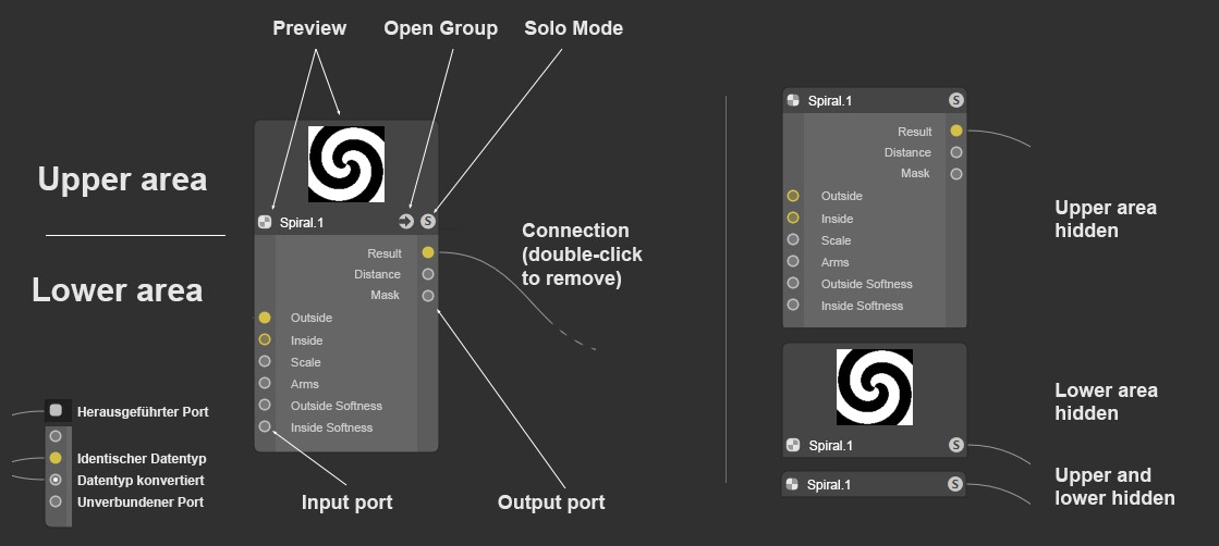
A Node is divided into an upper and a lower area:
The upper area of a Node
Above the Node is the Node name. If you have renamed the Node in the 'Base' tab, both your individual name and the original name will be displayed. The latter so that you always know which specific Node it is. You will then also find it under this name in the Help. The white colored name can also be changed by double-clicking on it.
In the Node top area there is - for Nodes where it makes sense - the constantly updated Node preview at the very top, i.e. when the settings of feeding Nodes change, this preview is also updated. You can open the preview with the small icon (2. from left). For this there are also commands available (see above)
As the calculation of this preview also takes up computing time, you can always leave it hidden. You will find the Preview option for new nodes in the Node Editor preferences.
Below the preview, on the left, is the Solo mode switch (see Solo), provided the Node supports previews, which is not the case for Scene Nodes, for example. To the right is the preview icon mentioned above.
Clicking on the 3. Icon that shows the folder symbol - this is visible only for group nodes - the group content is displayed in the Node View (double-clicking on the Node does the same).
The display mode icon on the far right can be used to toggle through the different port display modes, just like the 3 port commands do.
Below the icon row there is a color bar whose color can be freely defined with Color ('Base' tab). You can then find specific Nodes more easily. By default, some Node types are already assigned a color, but this can be changed at any time.
The lower area of a Node
In the sub-section, you will find input ports on the left-hand side and the output ports on the right-hand side, each with their name. Ports can be hidden and their order can be changed by moving them. Note that not all input ports are necessarily listed in the Node itself. These can then be displayed via context menu.
Certain Nodes (such as the Layer Node) even have expandable and collapsible port groups for each layer.
Ports have a specific color and sometimes different shapes depending on the data type they process (see next paragraph).
Ports can be selected (with the usual Shift and Ctrl keys to add to or exclude from the selection) to apply certain commands to them (see Node menu or context menu).
Finally, there are also so-called variadic inputs or outputs on some Nodes. This means that any number of these ports can be present. A classic example of this is the Children inputs on a Scene Node. The required number of these ports can be set individually using the Add Children and Remove Children buttons, which can be found in the Node's Basic settings in the Attribute Manager. This is even faster if you place the mouse pointer to the right of the name of these inputs on the Node. A plus symbol will then appear there next to the subobject group entry, so that you can add new inputs of this type directly in the Node Editor by simply clicking on them. If you place the mouse pointer next to the ports below, a red x icon will appear. Clicking on it removes this port from the Node again.
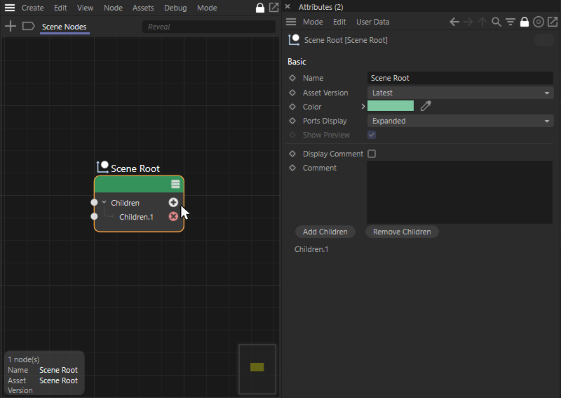 The number of variadic ports can be set directly on the Node with mouse clicks on the + and x buttons. Otherwise, you can also use the Add Children or Remove Children buttons in the Node's Basic Settings for this purpose.
Data types and colors
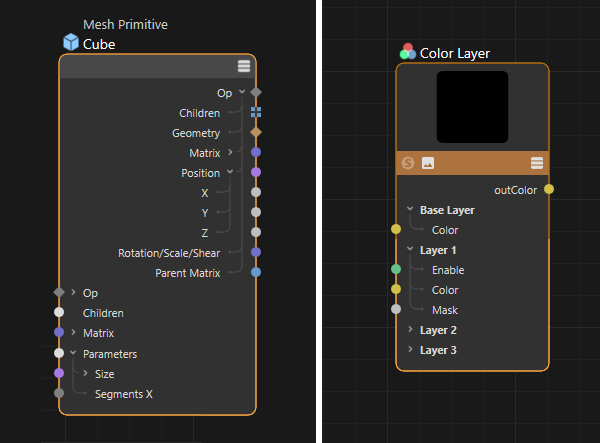 On the left is the scene node of a basic cube object. On the right is a color layer node from the Redshift material system.
Inputs and outputs are color-coded. The data types expected or output there are indicated by the coloring. The main types here are:
- A dark gray diamond provides the op information, which stands for all data of an object. These outputs can be linked directly to the Scene node, for example, to display objects in the views. These ports can be expanded in order to obtain individual access, e.g. to the Geometry, the Matrix or all Child objects of an object.
- Dark gray circle ports are made for integer values, i.e. for numbers that do not have a decimal part. You can recognize this port type in the illustration above, e.g. at the Segment X input on the Cube scene node.
- Gray circle ports process floating point values. These can be greyscale maps, for example, or simple numerical values that have a decimal part, such as the individual values of the Size on a Cube or the Mask inputs on the Color Layer node above, which can also work with greyscale.
- Light gray circular areas represent complex data types that can transmit data packets with different data types. In the illustration above, this applies to the Parameter input of the basic Cube object, for example.
- Blue rectangular areas mark data records that have been collected in a collection or in arrays. You can see this port type e.g. in the figure above at the output side of the cube base object. Object distributions are also passed on via such ports and can then contain color values in addition to matrices.
- A brown diamond is responsible for geometry, i.e., splines, as well as the points, edges and polygons at Scene Nodes.
- Purple circle ports handle complex matrices (in contrast to the basic matrices on light blue circle ports) and can therefore process several vectors simultaneously, e.g. for position, size, orientation or shear.
- Pink circle ports are intended for vectors, e.g. a position, a direction or also for normal maps consisting of RGB color values.
- Light blue circle ports are used for various types of data, e.g. for selections or settings controlled via menus. Simple matrices consisting of three vectors are also exchanged. The specific data type behind such a port can also be clarified by clicking on the port name and taking a look at the info area of the Node Editor.
- Yellow circle ports are reserved for color values. In addition to the usual three color components red, green and blue, alpha information of a color can also be exchanged via this.
- Green circle ports process bool signals, e.g. the status of an option (on or off). This information can also be automatically converted into the numerical values 0 for Off (FALSE) and 1 for On (TRUE).
- Entries without ports can often only be observed in group headings, as can be seen in the figure above for the Color Layer node from Redshift (Base Layer,Layer 1, Layer 2, etc.).
As known from XPresso, it is also possible to connect inputs and outputs of different types. As a rule, a meaningful conversion of the data types then takes place. For example, a texture can also be linked to an input for floating point values. The RGB values of the texture are then automatically converted to brightness values. In this way, color textures can also be used to control the Roughness of a "BSDF" layer, for example, or you can use a brightness gradient to control a floating point or integer value. Such conversions of data types are indicated at the receiving Node by an additional dot at the corresponding input.
Loop synchronization
Loops play an important role in programming and also in the use of Nodes, because they allow a complete Node graph or even only a part of the setup to be run multiple times during an update cycle.
You can often think of a loop as a fixed number of numerical values that are output one after the other, for example, as a sequence 0,1,2,3,4. These values can then be included in a position calculation, for example, which is then passed to an object. For each numerical value, an object copy is automatically created in your scene.
The following image shows an example of this.
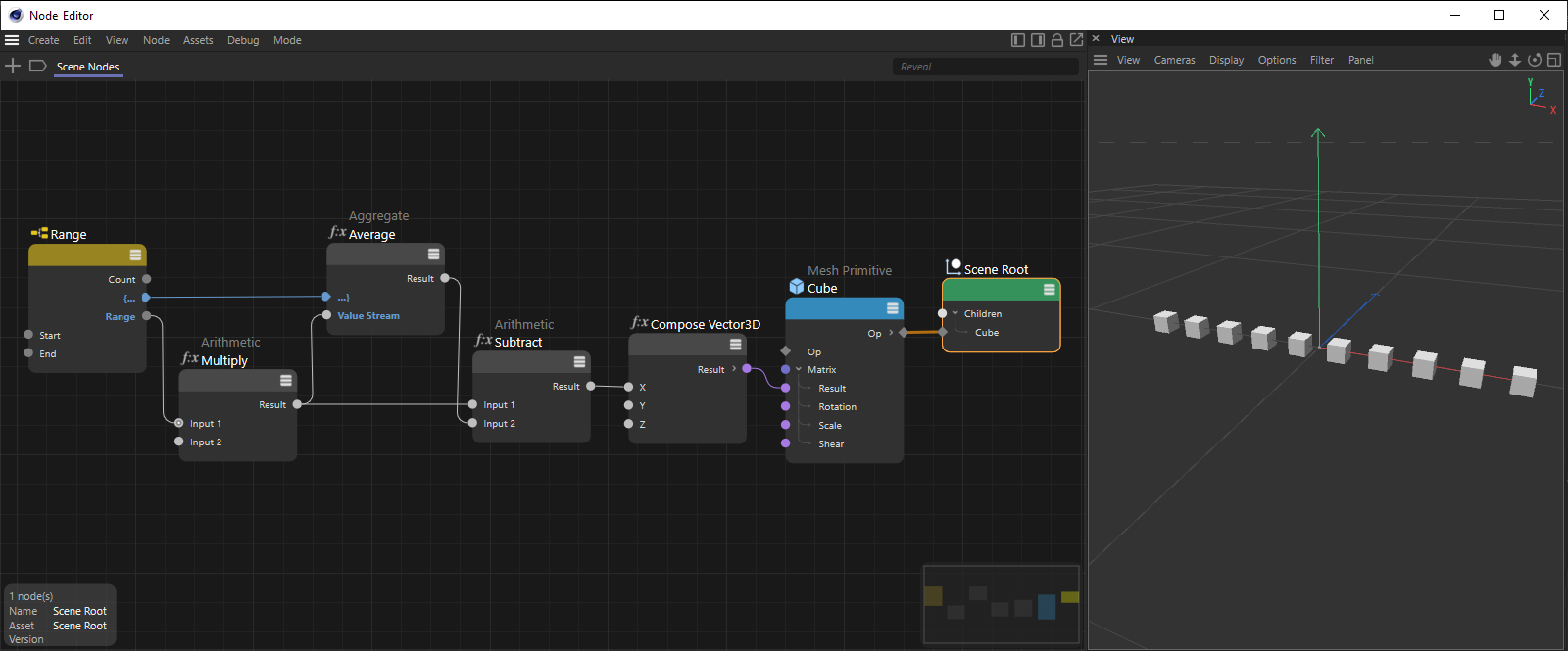 Example of linear distribution of object copies placed centered around the origin.
Nodes, such as the Range Node, which can be used to define loops, offer ports marked with a curly bracket. This allows Nodes of this type to communicate and synchronize with each other. This allows a sequence to be defined within the Node graph in which calculations take place.
In the example abov, the Range Node outputs a sequence of numbers between 0 and 10, which is multiplied by a fixed value to calculate different positions along the X-axis, which will then be transferred to objects.
To ensure that the positions are always calculated centered depending on the range output, a Aggregate Node in Stream Mode calculates an average value of all position values. This calculation must be performed first so that the Subtract Node can access the final result of this calculation. For this to work, the bracket ports of the Range and Aggregate Nodes will be connected. The symbols on these ports form a frame with an open and a closed curly bracket, indicating that this area - including the enclosed arithmetic node - is to be treated separately from the rest of the Node graph.
However, the bracket ports can also be used in a staggered manner to implement nested loop passes, as in the next example.
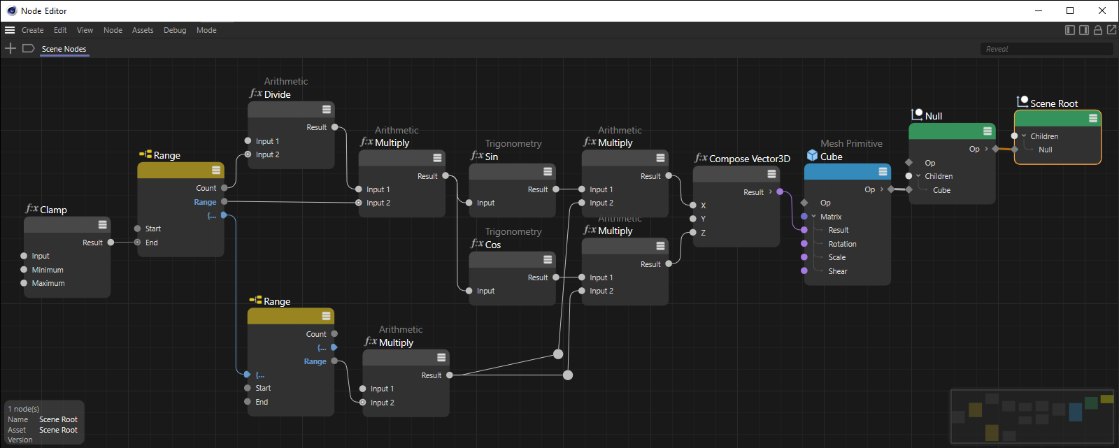 Range Nodes can be used to output ranges of numbers one after the other. The bracket ports can also be used to link several of these Nodes to create nested loops. For each output number of the left Range Node, the complete value range of the second Range Node is output.
In the example above, two Range Nodes are used one after the other. By connecting the bracket ports, these Nodes communicate with each other and synchronize the output of your values. Whenever the left Range Node outputs a new value, the right Range Node will run through all the values defined in it and output them one after the other. In this way, it is very easy to create regular grids for position values, for example, or to traverse UV coordinates. The X or U values will then be calculated by the first Range Node, for example, and the Y or V values by the second. In these cases, all bracket ports show only open curly braces. The subsequent Nodes are equally dependent on both Range Nodes.
Generally, these connections between Nodes used for synchronization are displayed in blue color and the ports that output a sequence of values also appear in blue color.
The context menu
Right-clicking on a Node/Port opens an extensive context menu consisting mainly of commands from the Node Editor menu. These are described elsewhere. Not described there are these:
This command is only available if the Node provides a Geometry output and if it is located within a group that has a Geometry output. By calling up this command, an automatic connection will be established between the Geometry output of the Node and the Geometry output of the group. As the command can also be called up using the shortcut Q when a Node is selected, it is possible to quickly extract geometry from an asset construction group, for example, in order to be able to directly examine the geometry calculations up to this Node. You can find more information on this in the discussion of the assets on this page.
An existing connection to the Geometry output of a group can also be removed by calling up the command again.
Herewith corresponding Nodes (e.g., basic geometry objects) can be switched from base Node to OP Node - and vice versa.
With a node, not all inputs listed in the Attribute Manager must also be listed as ports. Sometimes only the most important input ports are shown. If you call Add Input, all hidden ports will be listed here. If you select one, this input port is shown again (with All all input ports are made visible).
This menu item is not available if all input ports are shown.
Normally all outputs are listed. However, if outputs have been hidden (e.g. using the Remove Unused Ports command), they can be made visible again by selecting an output port listed here.
Connect Node
This entry only appears when right-clicking on a port that is not yet connected. A list will then appear from which you can select a Node to link. If there are several output ports per Node, move the mouse to the small black arrow and the output ports to be selected will be displayed. In addition to the complete asset list, the first entry here is Existing Nodes, which lists nodes that are contained in the current node view. In addition, there is the entry Group: Add New Output here, with which you can lead a port out of a group (see Input and Output group areas).
Note that this list is dynamically generated and suggests only matching Nodes.
Replacing Nodes
This replaces the 'feeding' Node for the current connected input port with one selectable from a list. Note that here the complete Node chain at the Node to be replaced (i.e. feeding it) is deleted. This only applies to Nodes to be fed: Nodes hanging on their output port are unaffected.
Textures
All loaded textures are listed here, from which you select one, which is then introduced into the input port with a Texture node. This command is only available when using the Material mode in the Node Editor.
Load textures
This command opens a file selection dialog with which you select a bitmap or a video, which is then introduced into the input port with a Texture node. This command is only available when using the Material mode in the Node Editor.
Remove port instance
Some nodes, such as the Redshift Ramp node, offer you this command. You can use it to delete elements such as layers or nodes.
Since these are again variadic ports, you can however also edit the number of these ports directly at the Node with the mouse. If the mouse is placed to the right of a variadic group port (e.g. next to the Ramp for a Redshift Ramp node), a plus symbol appears there, which can be used to add additional nodes in the color or value gradient. If the cursor is placed next to these ports, a cross symbol (x) appears instead, which can also be used to remove individual ports.
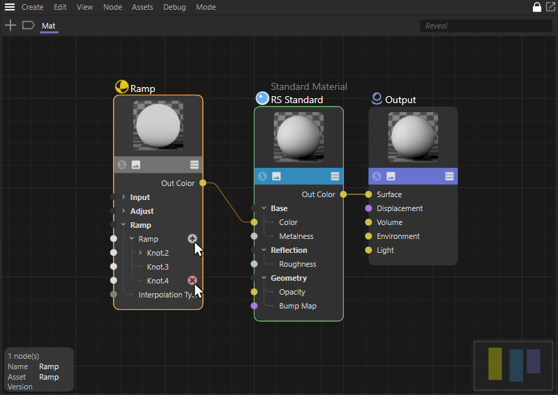 Variadic ports can be added or deleted directly on the Node.
Use this command to hide selected ports. This works only with unconnected ports. The hidden port then appears in the list just described under Add Input (and can thus be shown again).
Note also the command Show All Ports and the next two commands described there. This is a different functionality of displaying or not displaying ports.
When calling up these commands, several Nodes should already be selected, as the selected Nodes can be moved horizontally or vertically relative to each other in order to achieve an orderly placement within the Node Editor and thus improve the clarity and legibility of a circuit. Similar commands for automatically arranging Nodes are also available in the menu of the Node Editor for the entire graph or a selection of Nodes. However, this is mainly about avoiding overlapping Nodes. With the commands in this context menu, the selected Nodes are aligned flush with the left, right, top or bottom edges or centered horizontally or vertically. The following illustrations document this effect.
 The original setup can be seen at the top. Below you can see the results after selecting Align Top, Align Vertical Centers and Align Bottom, which align the selected Nodes at their top or bottom edge or centered at the center.
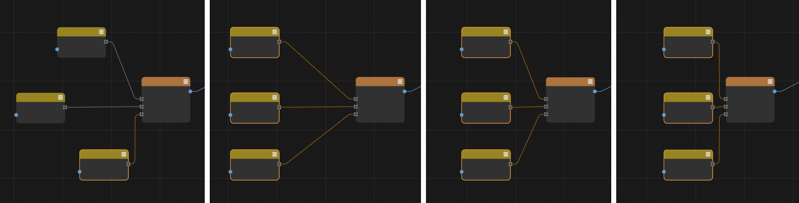 Alignment is used here on three Nodes placed one above the other (see initial position on the far right). The following images on the right show the results after selecting Align Left, Align Horizontal Centers and Align Right. The Nodes retain their vertical spacing and are only moved horizontally.
This command appears only when the context menu for a Node is opened and enables the Display Comment option in the Node's Basic Settings (or the Display Comment option for Redshift Material Nodes). This allows the text input of a comment directly under the Node. This can be very helpful to keep track of more complex Node graphs and, for example, to describe the function of individual sections of the graph in this way. Invoking this command again will also hide the comment if needed.
This entry appears only when right-clicking on a node and allows both selecting one of the default colors for the different Node categories or assigning an individual color by opening a color picker. The corresponding color is used to color the title line of the Node.
Details about these two debugging tools can be found here. These functions allow you to directly read the values provided by ports, making it easier to find miscalculations in your graph, for example.
Most of the parameters have a preset value that is predefined at Node recreation. With this command - listed only if the Node is not connected - you reset any values that may have been adjusted to this Default value.
Port out
Calling this command (only useful if the Node View shows the contents of a group) creates a connection to the outside or to the parent hierarchy. See also The input and output group areas.
This allows you to copy values/types of individual ports into the buffer (for a port with integer value 4, for example, it looks like this: int64:4). With Paste Value these can be inserted for other selected ports. As far as possible, data types are converted in the process.
This command copies a data type (for a port with integer value 4, this would be int64, for example. Of course, this makes little sense for such simple data types. However, since it is possible to create extremely complex data types (e.g. an Array Collection with different data types as output by Distribution scene nodes), you can save a lot of time by simply copying the data type and pasting it back in at the appropriate place. For example, in a Compose Container node, where you can also define data types, click on the button for Data Type on the far right and select Edit DataType... and copy the data type into it.
You can activate Solo functionality for material nodes. If this Node has multiple outputs, one of them must be defined as a Solo port. That's what you do with this option.
In the upper area of a Material Node you will find the Node preview. If a Node now has several outputs, this option can be used to specify which output is to be displayed there.
The connections
To connect one node port to another, proceed as described here.
Connections can also be selected, and as (almost) always Shift and Ctrl can be held down to add to or exclude from the selection (rectangle selections also work). What can be done with selected connections? They can be deleted e.g. with the known keys or edited via context menu with some commands described below (here only the commands not yet described elsewhere).
Deletes the selected connections.
Muted connections are shown with a dashed line. Here, values are not taken from the previously arranged Node, but from those defined in the Attribute Manager. This allows connections to be temporarily deactivated, e.g. for test reasons.
Other Node Editor components
The icons located in the upper right corner
You will find these icons at the top right of the Node Editor, described from left to right:
- Show assets on the left edge of the Node Editor: This displays an instance of the Asset Browser on the left edge of the Node Editor to enable the selection and addition of nodes or textures to a graph. Otherwise, you can also open the Asset Browser at any time by double-clicking in an unoccupied area of the Node Editor.
- Show attributes on the right-hand side of the Node Editor: This is particularly helpful when using an undocked Node Editor, which may hide the Attribute Manager. In addition, mouse paths can generally be shortened if settings on a selected Node can be displayed and edited directly within the Node Editor.
The attribute area in the Node Editor also has the advantage that it only displays Node parameters. This means that the selection of elements in the Object Manager or in the Viewport, for example, does not cause an existing parameter display in the Node Editor to disappear. - Lock Node view: Normally, the Node view always shows the Node material currently selected in the Material Manager, for example. If you do not want the view to switch when a new material is selected, use this to lock the node view. However, this can also help to distribute different groups or sections of complex circuits across several Node Editors and thus always have them in view.
- New Node Manager: this can be used to open a new Node Editor. This can be useful, for example, if you have Node networks with hundreds of Nodes and want to work in several areas at the same time. Or you want to have the Nodes of two Node Materials visible at the same time (see also previous paragraph). A newly created Node Editor has the lock activated by default.
The connection icon
The big innovation compared to the old Attribute Manager are the link fields, which have been replaced by the connection icon. Node inputs can either be fed with values by simply entering values in the parameter fields or - and this is new - connect Node inputs with the outputs of other Nodes, i.e. create a link (i.e. what Nodes are all about).
Click on the connection icon to the right of the parameter name and select any node from the Connect Node context menu to connect it to the input you have clicked on (you can of course also simply connect the ports in the node view). The selected Node is created and linked:
By the way, bitmaps can always be dragged from outside Cinema 4D anywhere onto a parameter (incl. parameter name, connection icon and GUI element) to link the corresponding parameter by means of an Image Node.
As soon as a parameter is connected with another Node, the following applies:
- a small arrow appears instead of the animation icon. Click it to show the parameters of the docked Node.
- the parameter can no longer be animated with the usual animation icon - this will be hidden (of course, you can still animate the parameters of the connected Node). This means that a parameter cannot be controlled by the Timeline and another node at the same time.
So the animation icon shows dependencies in the animation and XPresso context, while the connection icon symbolizes dependencies in the shading and renderer context.
The connection icon can assume these 3 states:
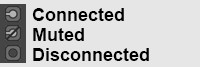
- Connected: The values flow from the linked Node into the Node input, to the right of the connection icon the linked Node name is displayed. This can be clicked on to select the associated Node and display its settings.
- Muted: There is a connection to another node, but its values are not adopted (but those defined in the Attribute Manager ).
- Unconnected: the values defined in the Attribute Manager are used.
When you click on a connection icon, the following commands are offered, most of which you already know from the Port context menu. So the connection icon also provides similar functionality that can be accessed by right-clicking on a port in the Node View.
Only the connection icon's own commands are described below.
Add Layer
Here you are offered selected ports of different nodes for connection. The corresponding node is created on the existing connection and then enables, for example, the mixing of color values with the results of other nodes.
Insert converter
Here you are offered nodes that can be used to customize value ranges, for example. The node selected here is added to the existing connection.
Copy
This can be used to copy the connected output port to the clipboard and use...
Paste (Link)
...be connected to another input port. This means that several inputs can be linked to the same output.
Paste (Duplicate)
This command connects the output port located in the clipboard with the clicked input. In contrast to the previous command, a duplicate of the whole - feeding - Node is created.
Remove
This is used to delete the node connected to this parameter and its connections.
Show in Node Editor
Displays the corresponding nodes/ports in the Node Editor. Alternatively, you can click on the connection icon while holding down the Ctrl key. This allows you to quickly link several parameters selected in the Attribute Manager to nodes in the Node Editor, for example.
Show Subchannels
Some Nodes like the Layer Node or the Gradient offer you this mode. Activate this to display, for example, the layer settings as parameters that can be animated or also controlled by the connection icon. In addition, the input parameters of the feeding Node can be shown when you activate on one of the layers. In the following example, these would be the inputs of the Circle node:
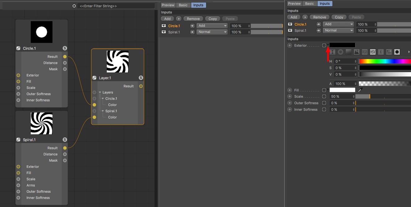
For the Gradient Node (click a handle and click one of the child connection icons to invoke the command), the parameters of all Nodes are listed.
Call the command again to switch back to the previous mode.
Inherit Interface
Some Nodes, such as the Distance or Value Node, can adopt the units and parameter representation of the subsequent, connected Node for input ports.
The Info Area
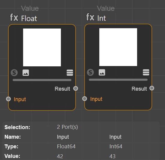 With multiple port selection it is also possible to compare the values.
At the bottom left you will find the scalable Info Area, which gives you some info for selected Nodes, connections and ports.
These are for Nodes:
- Selection: the number and type of selected elements.
- Name: the node name as defined in the Basic tab.
- Asset: the invariant Asset name as defined internally. Why is a distinction made between Asset and Name? You can always rename the Name and you will have this new name, different from the one mentioned in the Help. Since Cinema 4D R23, however, both names are displayed directly with the Node.
- Version: When you create Assets, you can specify a version number, which is then displayed here - including date and time. This way you always know which Asset version you are currently using.
- Asset ID/ID: these are unique, distinctive IDs. These are without much information value for you. For Asset developers, however, these can be interesting.
- Errors: all kinds of errors can be displayed here (e.g., if an autoconversion of data types fails).
For connections, these are additional:
- Selection: number of selected connections.
- Port Type: the data type that the port expects as input or outputs.
- Connected Type: the type of data that "flows" through the connection.
For ports, these are additional:
- Port Value: if the port is not connected, the value set in the Attribute Manager is displayed here.
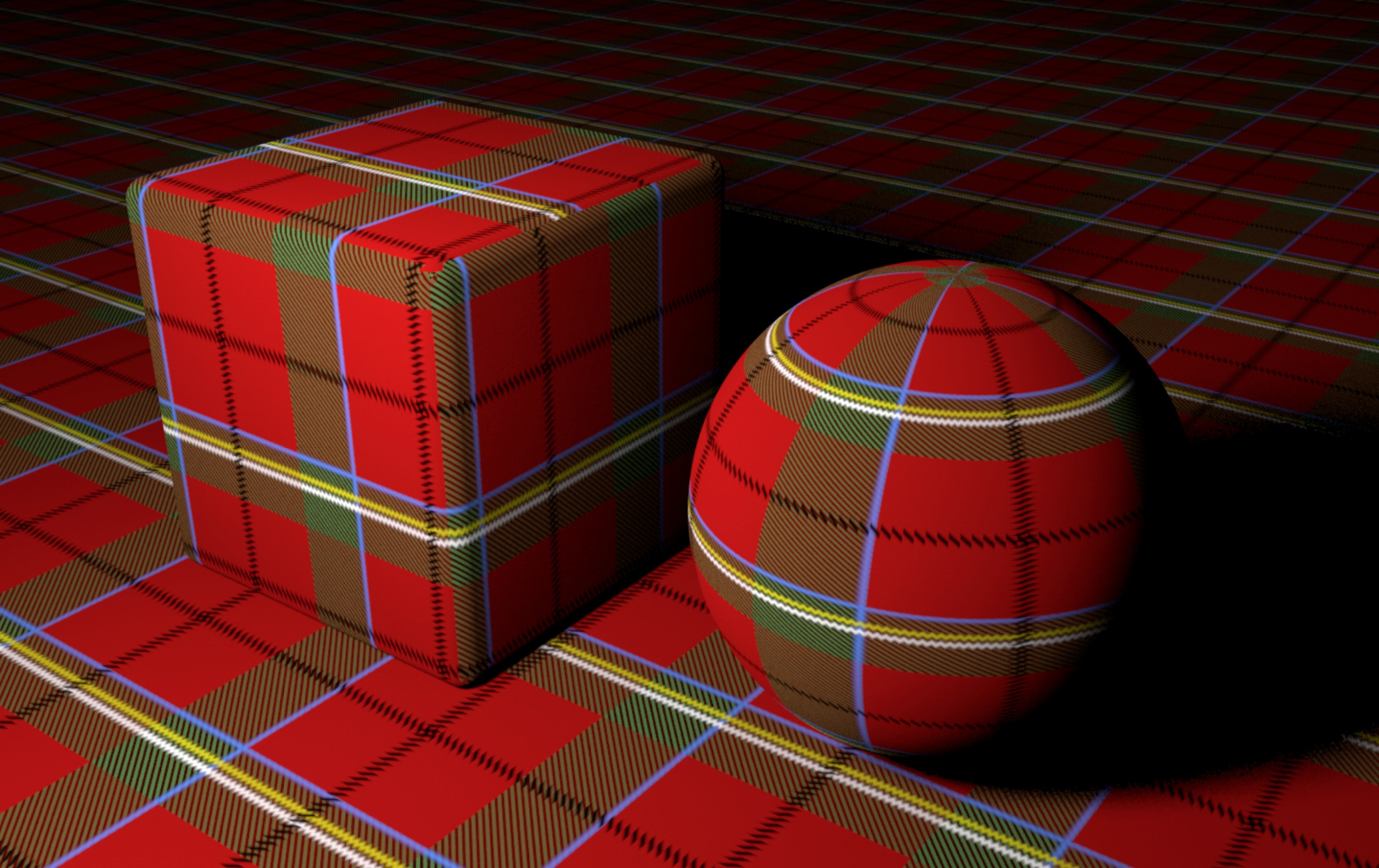
Material Node Example Scene
The following material was created entirely with Nodes, using no bitmap as texture.
Load the following scene:
You can start to see here what is possible with Nodes. Right-click on the material and select Node Editor to take a look inside the node graph. Note the 'Plaid' Group Node, this hides more Node networks.
Features of the Scene Node Editor
In contrast to the descriptions above, the scene Node Editor has some special features:
- Some nodes in the Scene Node Editor have a thick op connection, as can be seen in the following illustration between the Capsule node and the Scene node:
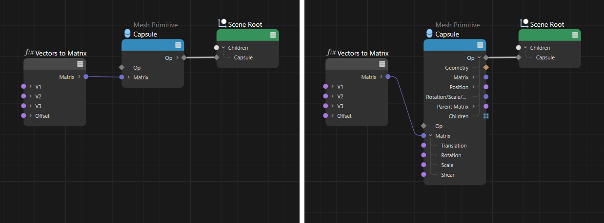
These connections are a bundle of different values. Open it with the small arrow on the Op output port to display the value type. To create visible geometry in the scene, an Op output should always be connected to the scene port. Other ports, such as the Matrix input in the figure above, can also be opened to set or read out individual components of this data format. - Nodes in the Scene Node Editor usually have to manage without a preview.
- Nodes in the Scene Node Editor do not have a Solo mode.
If you search for Oil Tank in the Asset Browser, for example, you will now only see 1 hit, unlike in older versions of Cinema 4D. This is due to the fact that not all Node versions (Base Node, OP Node) are displayed anymore. Instead, drag an Oil Tank into the Node Editor or directly into the Object Manager. The Oil Tank is then evaluated as a Base Node, Op Node, or Asset Capsule. You can switch between base and op node in the Node Editor using the context menu command Toggle Node Type.