Object Properties
By default, objects are shown from the viewpoint of a central perspective projection. Alternatively, choose other types of projection.
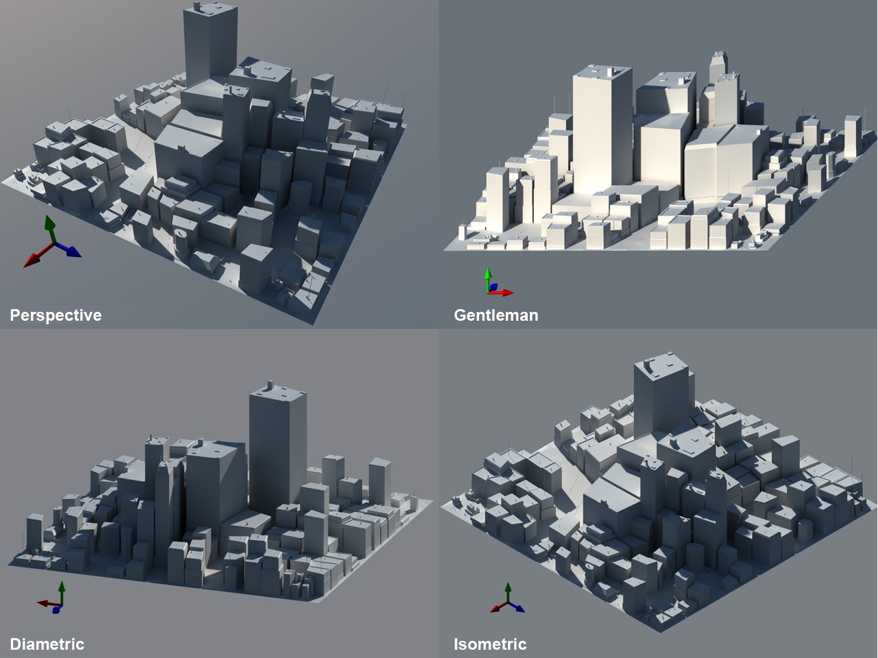 From left to right: Perspective, Gentleman, Diametric, Isometric.
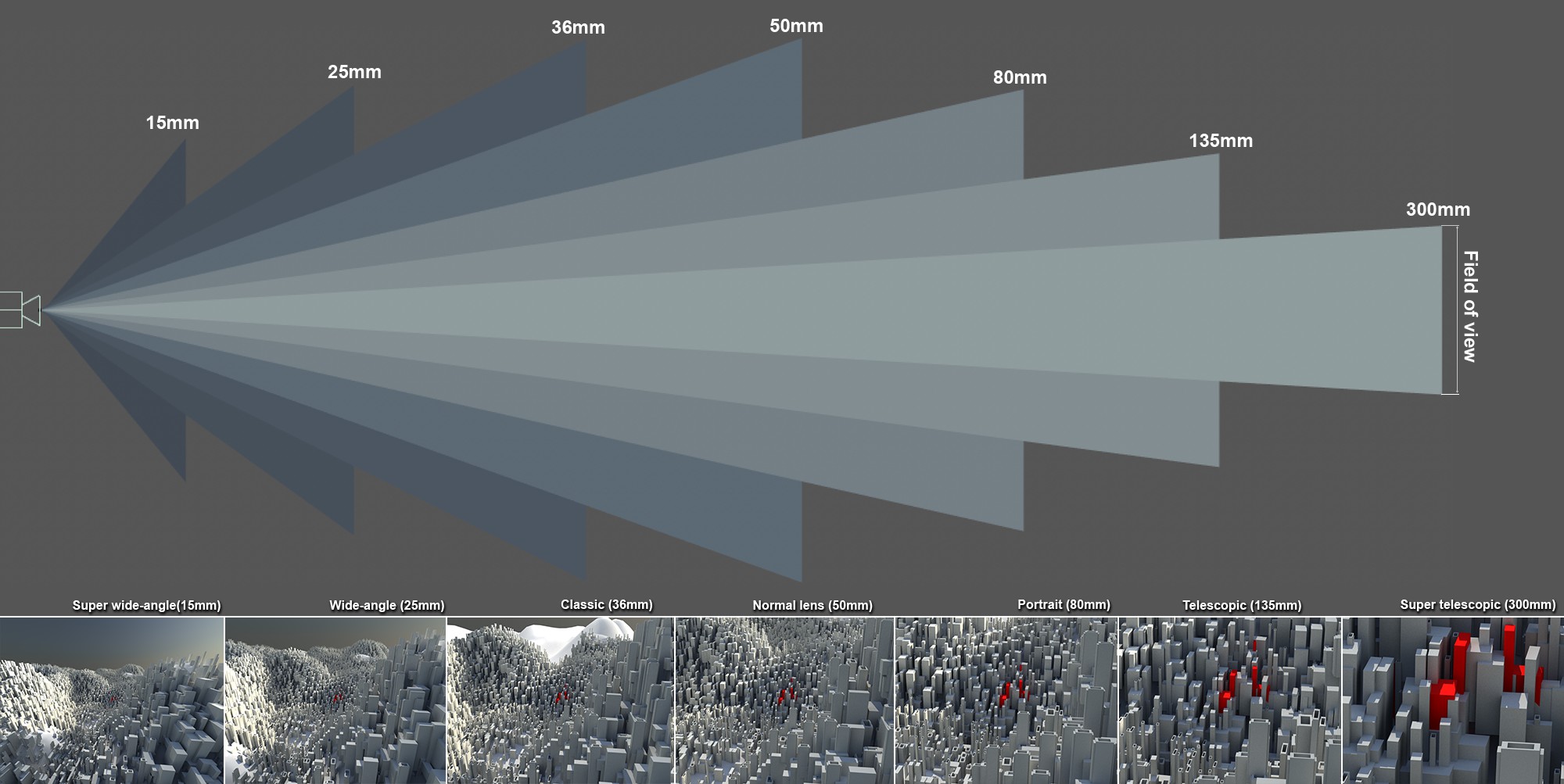 Increasing focal length and decreasing field of view from left to right.
In a real camera, the focal length represents the distance between the lens and the film. Small focal length values are used for wide-angle shots and present a wider view of the scene, but also distort the image (especially very short focal lengths). Larger focal length values zoom into the given scene accordingly. The greater the value, the less distorted the image will be until the perspective effect is lost completely with extremely large focal length values and the parallel projection effect increases.
The Focal Length is directly linked to the "field of view" in the formula illustrated below.
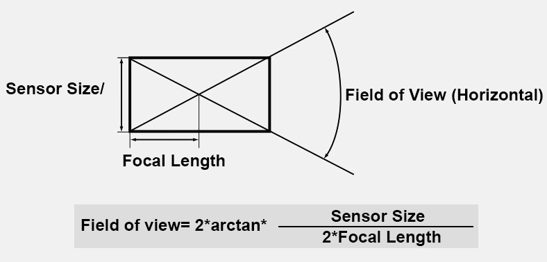
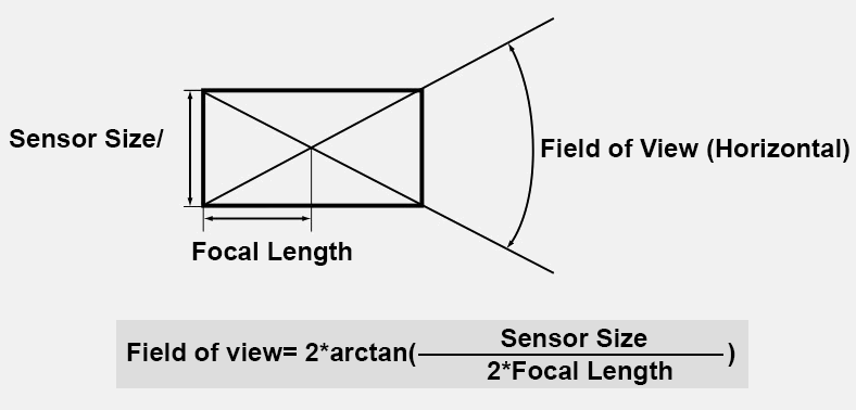
Larger Focal Length values produce a smaller field of view and vice versa.
Here you can select from several pre-defined focal lengths or you can define your own.
The following applies for depth of field (Physical Renderer): The larger the focal length value, the smaller the depth of field (the region in the direction of view that will be in focus) and vice versa. See also Depth Of Field.
Sensor Size (Film Gate)[1.00..2000.00]
In a real camera, this value defines the horizontal film or sensor width in the camera onto which the light falls. For common cameras, this is usually 35mm (technically speaking, actually 36mm). In reality, this value is mostly constant and cannot be modified - unless you buy a new camera.
In combination with the focal length, the Field of View (Horizontal) value is determined.
You can select from numerous sensor sizes or define your own by selecting Custom. If you modify the Sensor Size (Film Gate) value without modifying the Focal Length, the field of view will still change. Any depth of field, however, will remain unchanged.
The 35mm Equiv. Focal Length value is displayed since analog 35mm film is still very widespread in the world of photography despite the proliferation of digital sensors in varying sizes. Fans of traditional photography can use this as a reference for the image detail or the enlargement of the 3D scene or digital camera.
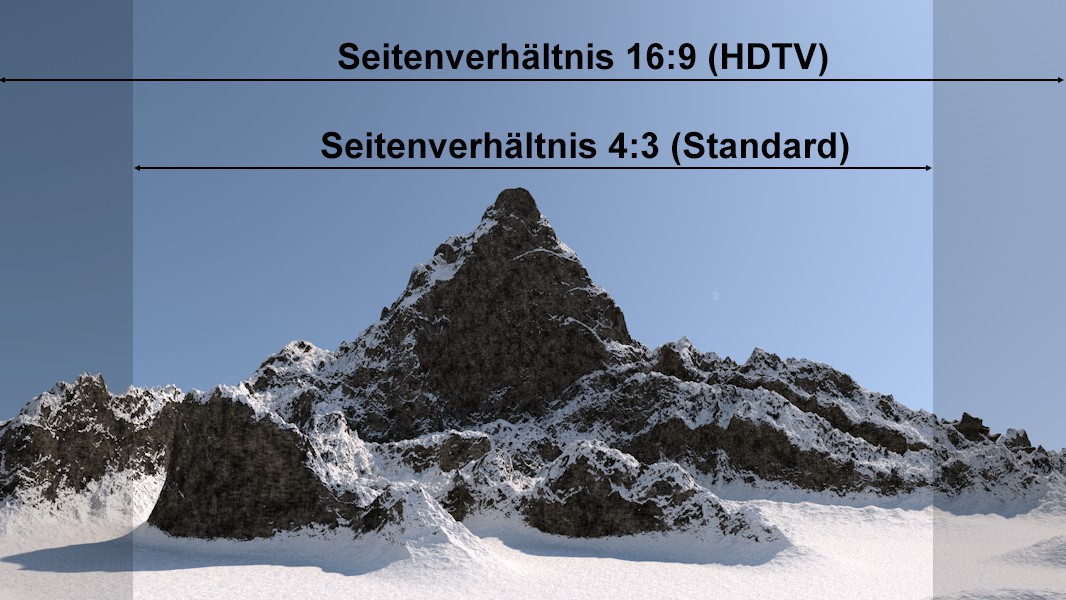
The sensor size has to be adjusted if the aspect ratio you want to render should be modified while maintaining the same perspective.
Use the following formula to calculate the sensor size:
New sensor size = old sensor size * (new Width / old Width)
Example: You have a scene in which the render format is set to 800 x 600 with a sensor size of 36 mm. You want to output the scene with an aspect ratio of 16:9 while maintaining the same perspective. First, you have to ascertain the new image width: switch to the Render Settings and set Film Aspect to HDTV (16:9). The Height value will be modified accordingly, which is what you don't want. Enable the Lock Ratio option and set the Height value back to 600. The following Width value will result: 1066.667.
Use this value in the formula above. The sensor size will be 36 mm = * (1066.667/800) = 48mm.
Field of View (Horizontal)[0..174°]
Field of View (Vertical)[0..174°]
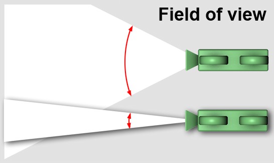 Camera from top: large and small (horizontal) field of view.
The field of view represents the camera's horizontal and vertical angle, respectively, to the scene. The field of view is directly linked to the focal length. The greater the focal length, the smaller the field of view and vice versa. A small field of view represents a camera with a telephoto lens; since only a small portion of the scene to be photographed enters the camera, this portion naturally appears very large on the light-sensitive surface of the camera, resulting in a zoomed-in image.
Incidentally, Field of View (Vertical) changes if the proportion between Width and Height are modified in the Render Settings.
The Zoom value can only be defined if a parallel perspective (this includes orthographic views) is used. This setting then defines the scaling of the view.
An important number here is 1024 because if a Zoom value of 1 will cover 1024 Cinema 4D units. This is always important when outputting precise pixel renders. Example: You have a sphere with a diameter of 12 cm and you want it to have a diameter of 120 pixels for rendering. Use the following formula to define the zoom:
Zoom = 1/(Width)*1024, which is defined in the Output tab in the Render Settings.
Precise pixel render outputs are, for example, needed if a rendering has to be adapted to fit existing footage (e.g., animated masks, satellite photos, etc.).
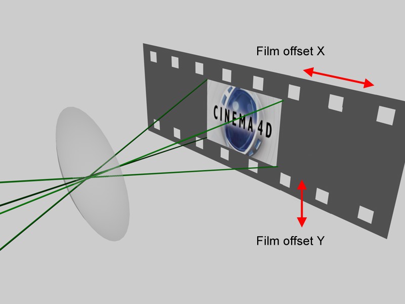
Suppose the Cinema 4D camera worked like a traditional film camera, with images being recorded onto photographic film one after the other. Now imagine if additional image information could be recorded by moving this film along the X and Y axis (beyond the strip of film in the example). This is exactly what these parameters do. Cinema 4D takes this one step further in that it does not restrict itself to the size of the filmstrip.
So what use is all this?
-
First, it lets you shift the part of the image displayed without changing the perspective.
This is especially useful for adjusting views in architectural visualizations. Perspective, linear direction and linear angles are not affected. - Second, the 16,000 x 16,000 and 128,000 x 128,000 pixel render limitation has been eliminated.
A special trick makes it possible to render images to any given size. This is how it works: Animate Film Offset X and Film Offset Y in steps of 100% for each image. Split the scene into separate parts that will be rendered sequentially. Choose an image format as your output format (don't choose video).
Once you are done rendering, you will have several images (none of which may exceed a resolution of 16,000 x 16,000 or 128000 x 128000 pixels) that you can then piece together in an image editor.
Example:
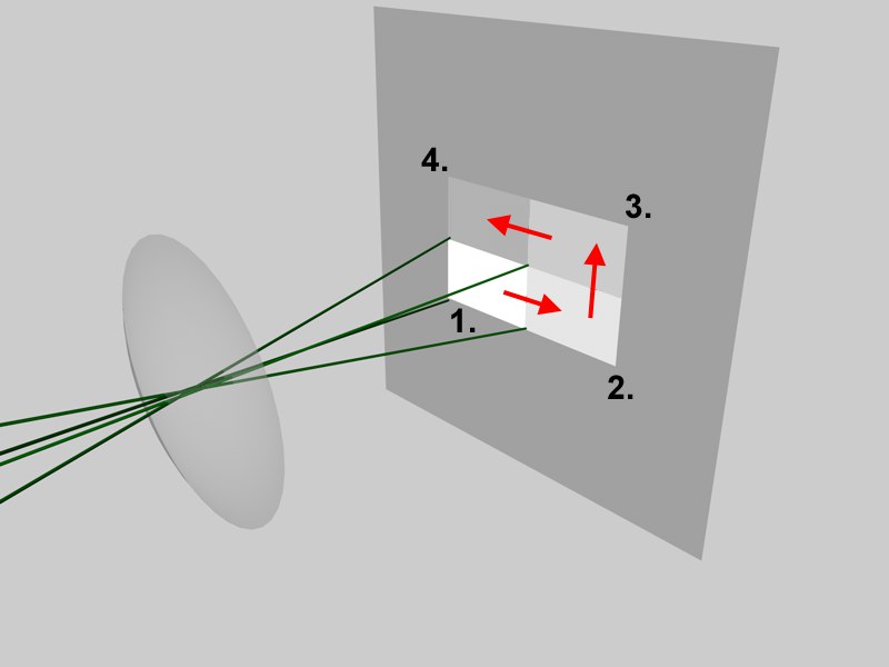
For the example, the scene was been split into four pictures. The camera's Film Offset X and Film Offset Y were animated over four frames as follows.
- First frame: Film Offset X / Y = 0% / 0%
- Second frame: Film Offset X / Y = 100% / 0%
- Third frame: Film Offset X / Y = 100% / -100%
- Fourth frame: Film Offset X / Y = 0% -100%
The result is four separate images that you can piece together in an image editor.
Note: This and the following 3 parameters are primarily designed for use with the Physical Renderer.
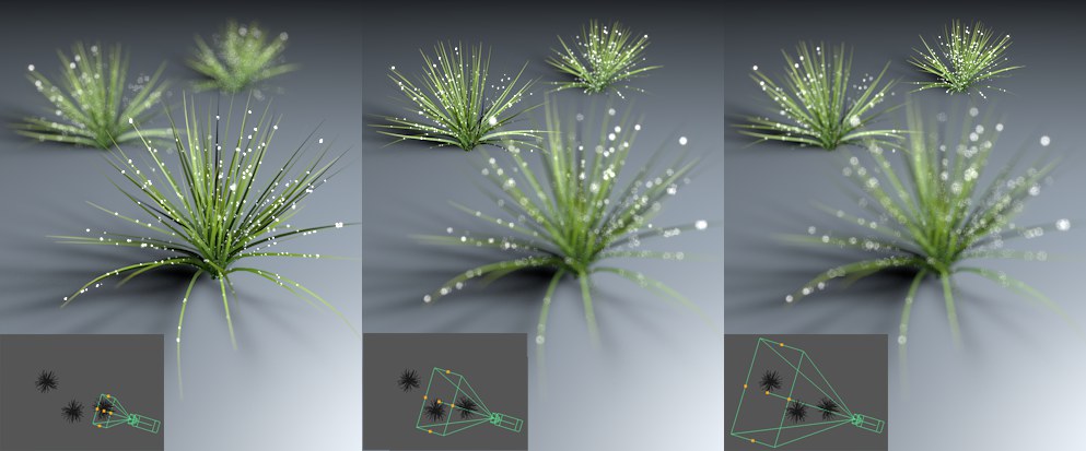 The Focus Distance defines the blur plane.
The Focus Distance, measured from the camera's origin out (=film or sensor plane), defines the distance to a plane that lies perpendicular to the angle of view, on which all objects are displayed perfectly in focus. In front of and behind this plane, all objects are rendered progressively blurred. This value can be defined interactively with the mouse in the Viewport by clicking and dragging on the camera's center front handle.
A second function of this parameter is to define the position at which a depth map should be calculated (see Start).
The arrow at the right of the setting can be used to interactively set the focal length in the Viewport (this only works in the Perspective or Parallel views) to a specific object. The camera will not be rotated. The distance to an imaginary plane lying vertically to the camera's angle of view on which the selected object vertex lies will be used.
If the camera has been assigned a Target tag, the target object will automatically be used by Focus Distance for calculation.
The Focus Distance can also be defined using any object. Null Objects are well-suited for this purpose. However, the camera will not rotate in the direction of this object. Only the distance in the camera's direction of view will be applied.
With imported scenes in particular, in which the object origins (axes) are centered globally, that the focus distance is always calculated up to the axis. In this case you have to move the axis to the correct position (the ![]() Axis Center command an help).
Axis Center command an help).
White Balance (K)[1000.00..10000.00]
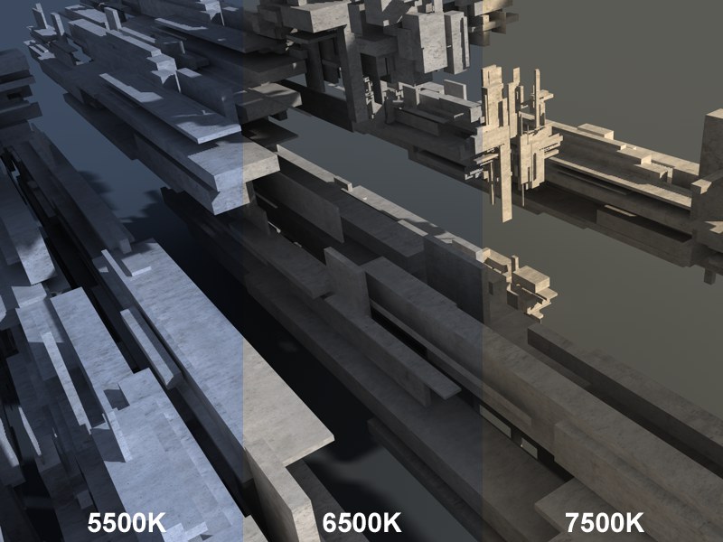 An outdoor scene (with sky) with 5500K, 6500K and 7500K White Balance, respectively.
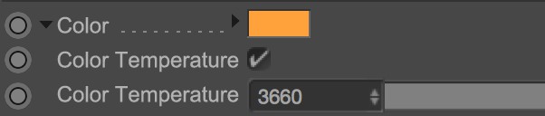
White balance is used to prevent light sources (e.g., sky, sun, candles, etc.) from colorizing white surfaces. Set the White Balance value to that of the light source's color (Tungsten refers to the filament coil in a light bulb). If the presets do not quite match your needs you can select the Custom option and define a custom temperature via the Custom Temperature (K) value. Color hues can be defined without having to change the color of the light itself.
As you can see in the image above, 5500K produces a slight blue hue and 7500K a slight yellow hue. The value 6500K (which is representative of daylight conditions), produces a grayed, cement-like hue (cement textures were applied to the objects in the image).
Color temperature is measured in Kelvin (the colors shown below represent the range emitted by an idealized luminous body):
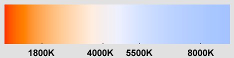
Of course white balance can be used to colorize renderings. The neutral value is Daylight (6500K). Generally speaking, lower values result in hues of blue and higher values in hues of yellow (directly opposite to the depiction above; the white balance, after all, is a corrective value).
Sometimes it is easier to apply white balance to lights instead of cameras. Enable this option to do so.
White balance will only work for light sources whose color is controlled via the Color Temperature (not the color chooser's K setting).
Note that this White Balance is a simplified method (does not take all elements into account (e.g., glowing materials)) of white balance. The camera white balance takes into account all elements within its field of view.
If enabled, the camera will be exported to the respective compositing application (see also here).