in
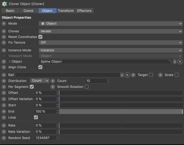
Object Properties
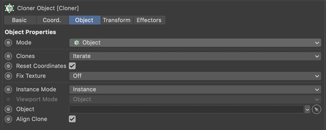
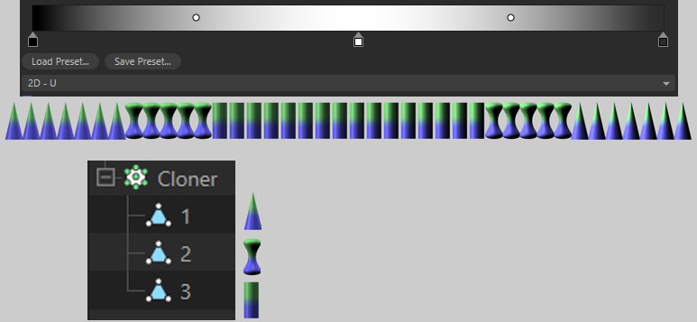
Here you can choose between the two basic modes, which distribution type should be used for the clones:
- Basic: This is the function that was used by default in Cinema 4D versions prior to 2026.1. Various predefined patterns and references can be called up via the Mode menu to determine how the duplicated objects should be arranged in space or alongside other objects. This is still the right setting if you simply want to place object copies along a direction, a spline, a surface or in a regular grid, for example. This is also the right mode for cloning on the positions of particles or matrices. Only for even more unusual distribution types do you switch to Advanced mode, in which nodes can then be used to control the clone distribution.
- Advanced: This mode allows you to control clone generation via Nodes. Some distribution types supplied in the Asset Browser are already available for this purpose, or you can configure a Nodes Distribution yourself and use it to configure the number, placement, rotation, scaling and coloring of the object copies. Here you will find more detailed explanations on how to configure your own clone distributions via Nodes.
For the Advanced Distribution type, you will find a link field here into which predefined Distribution Capsules can be loaded using the Browse button. You can also drag existing Nodes Distribution objects in the Object Manager into this field, or you can create a new Nodes Distribution using the Create button and link it here automatically. However, this type of distribution must then be filled with nodes in the Node Editor in order to display a distribution function.
The settings for a Nodes Distribution object linked here can be viewed by expanding the small triangle to the left of the Distribution link field, or you can select the corresponding Nodes Distribution object directly in the Object Manager to display its settings in the Attribute Manager. As is usual with Node capsules, double-clicking on a Nodes Distribution object in the Object Manager also automatically opens the Node ditor.
After selecting the Advanced Distribution Type, an Asset Browser can be opened, which automatically filters out only the available Nodes Distribution Capsules and makes them available for selection. Double-click on the desired distribution to assign it to the Cloner object. In addition, the selected distribution capsule is created directly in the Object Manager and can also be selected there in order to display its settings in the Attribute Manager. Alternatively, the Distribution link field can also be expanded in order to view and operate the settings of an assigned distribution directly in the Cloner object dialog.
If you prefer to search for these Nodes Distributions manually, you can find them in the Nodes > Distributions category of the Asset Browser. From there, the distribution capsules can also be dragged directly into the Object Manager or loaded there by double-clicking and then dragged from the Object Manager into the Distribution link field of the Cloner object.
The following distribution capsules are currently available:
- Cannonball Distribution
- Partition Distribution
- Projected 2D Grid Distribution
- Smart Hex Distribution
- Spline Bead Distribution
- Stack Distribution
After selecting the Advanced Distribution Type, a new Nodes Distribution can be created in the Object Manager and assigned as a distribution to the Cloner object. The Node Editor opens automatically, displaying the contents of this capsule so that you can configure your individual node-based distribution. The Node Editor can also be closed again at any time. By double-clicking on the Nodes Distribution capsule in the Object Manager, its Node Graph can be displayed again at any time in the Node Editor.
If you want to call up this start module for your own node-based distribution yourself, you can also find the Nodes Distribution capsule in the Asset Browser under Nodes > Asset Construction. From there, it can be dragged directly into the Object Manager, for example, and then linked as a Distribution on the Cloner object.
You can find instructions for configuring a manually added Compose Container node together with examples for creating your own node-based distributions on the documentation page for the Nodes Distribution.
A node distribution object assigned in the Advanced Distribution type can also influence the selection of objects grouped under the Cloner object via its Clone Type array. In this way, the node graph can also be used to determine where within the distribution which geometry should be used as an instance. However, the Cloner object itself also offers specifications on how its child objects should be processed via its Clones setting. You can therefore use this Clones from Distribution option to specify whether you want to leave the selection of the objects to be cloned to the Cloner object (option switched off) or to the Nodes Distribution used (option switched on).
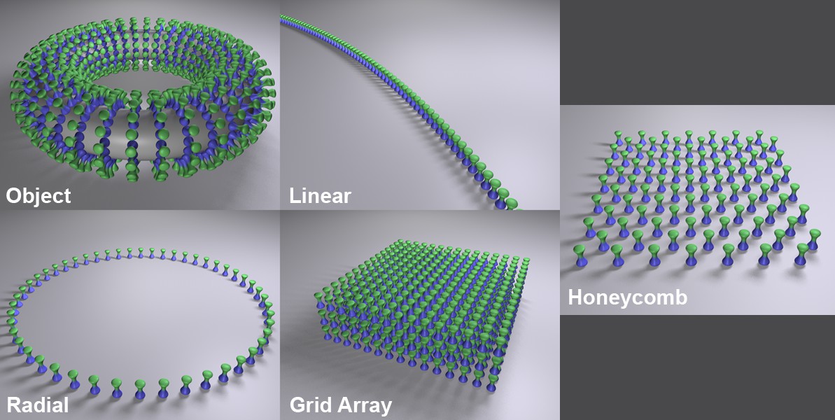
The distribution modes specified here are only available for the Basic Distribution Type and provide their own parameters, which are shown here in the Object tab. The following exemplary Distribution modes are available for selection.
To use node-based distributions - both those that can be created via the Asset Browser and individually configurable Node graphs - you must switch to the Advanced Distribution Type.
In this mode, the child objects of the Cloner object are arranged on other objects. There are two ways of telling the Cloner object which object the clones should be created on:
- The Cloner object is placed as a sub-object of the shaping object.
- Drag the Shaping object into the Object field.
If both are the case, the second case has priority.
The clones will be arranged as follows:
- Polygonal objects: points, edges, polygon centers, random distribution on the object surface, selections.
- Splines: Along the spline
- Particles (Particle Groups, legacy particle Emitters or Thinking Particle Groups): At the positions of the particles
- Matrix objects: A clone will be positioned at each matrix position.
In this mode, the objects are made child objects of the Cloner object - starting from the origin of the Cloner object - are arranged in a row, which can also have an arc shape. Each clone is moved, rotated or scaled a little, depending on what you have set under Position, Rotation and Scale further down in the dialog.
In this mode, the Cloner object's child objects are placed in a circle around the center of the Cloner object.
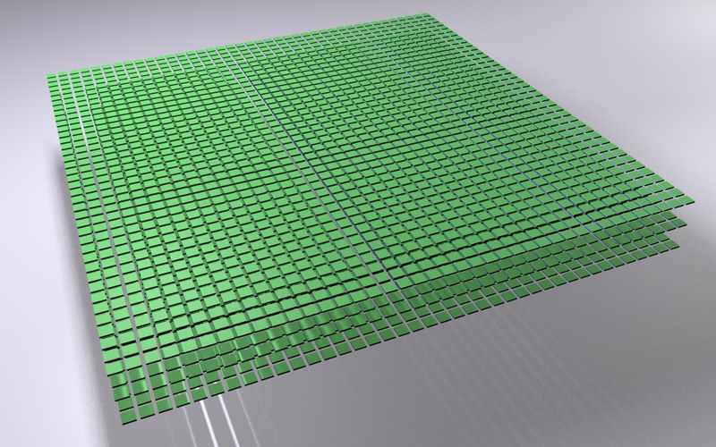
In this mode, the objects subordinate to the Clone object are arranged in a spatial grid. This is well suited for such grid-like effects, for example:
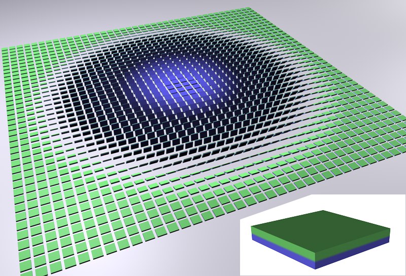 The cloned object at the bottom right is then varied in rotation in Grid mode using an Effector.
You can certainly imagine the spectacular effects that can be achieved if you animate the effector so that it passes through the grid.
As there are a large number of objects here and the editor display can therefore become very slow, the detailed settings of Cinema 4D work here:
- Editor: Options/Detail level (see Detail level )
- (see also Display Tag. The tag is placed on the Cloner object.
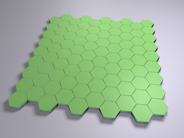
This mode provides a two-dimensional grid in which every second row is shifted horizontally so that the individual clone is aligned with the center of the clones above it. The result is a typical honeycomb pattern that can be used for brick walls or similar.
This functionality corresponds to that described under Linear mode.
This functionality corresponds to that described under Linear mode.
This functionality corresponds to that described under Linear mode.
The clones are fully-fledged duplicates of the objects to be duplicated. They consume the same amount of memory as if each clone existed as a separate object. Nothing else happens when you make the Cloner object editable. You will receive x full objects.
See Render Instance.
In principle, the same properties apply to this mode as for Render Instance (in particular the restrictions mentioned there). In addition, the clones are treated internally as a single object, which reduces memory consumption and further optimizes speed. This mode is particularly suitable for all types of vegetation. When it comes to cloning tens of thousands of trees or tufts of grass, for example, this mode is a must.
Multi-Instances work best when each instance consists of as few objects as possible.
Is it still worth using the Render Instance mode? Yes, this is still to be seen as a kind of reserve parachute. If undesirable behavior occurs with Multi-Instance - e.g., a certain functionality does not run as it should - switch back to Render Instance.
Some simplified - and therefore accelerated - display modes can be defined here for navigation in the Viewport. The render result will not be affected by this.
You have the following modes (the navigation speed decreases from top to bottom):
- Off: No instances will be displayed.
- Dots: The instance positions will be displayed with small dots.
- Matrix: The instance positions will be displayed with small squares (as usual for the matrix object).
- Bounding Box: The instances will be displayed with their bounding box. This allows the approximate clone sizes to be estimated.
- Full: The instances will be displayed in full.
The start value varies the random distribution of the child objects used for cloning in Random mode.
Objects
Here you can drag in particle groups, polygon objects, splines or MoGraph Matrix objects, for example, if you do not want to use the Cloner object in this way by arranging the shaping object as a parent object. Depending on which object is used as the shape, various parameters are displayed, which are described below.
You can use these links to jump directly to the description of the desired object type:
Polygonal objects
 Head model: © Bunk Timmer
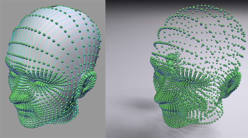
If you use the Cloner with a polygonal object, the clones will be arranged at its points, edges, polygons, surfaces or selections. Both polygonal objects and parametric primitive work. Subdivision surfaces can therefore also be used, whereby a vast number of points will be generated.
Aligning clones
The activated option aligns the clones: They are rotated with their Z-axis in the direction of the surface Normals or point or edge Normals. The remaining clone rotation can also be affected using the up vector described below.
If this option is disabled, the clone axis will be aligned with the axis of the object on which it is growing.
Up Vector
The activated Align Clones option clearly aligns the Z-axis of the clones, but not the rotation around it. Imagine a plane deformed by a Displacer Object and an animated noise, with clones arranged on each of its points. In the animation you will notice that although the Z-axes point in the direction of the respective surface Normal, the rotation around this axis varies more or less arbitrarily. If you now define an Up Vector (coordinate system: object on which the clones grow), this arbitrary rotation will be switched off. In principle, this works in the same way as with the Target Expression, except that you do not define a target object here, but select a predefined vector.
Alternatively, you can also use a Target Effector (see also Chapter 3.11 The Target Effector ), which does something similar.
Distribution
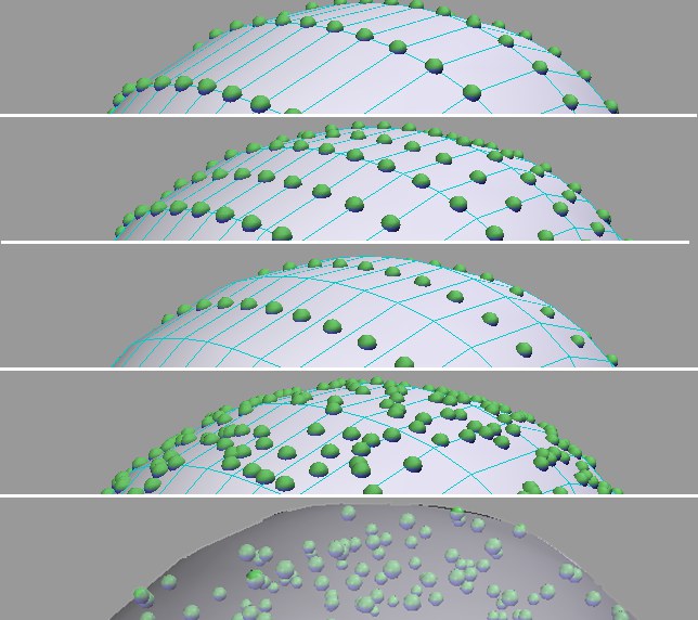 The modes from top to bottom: Point, Edge, Polygon Center, Surface, Volume.
Define here where the clones should be arranged:
- Point: One clone on each object point.
- Edge: One clone on each edge.
- Polygon center: One clone on each polygon center point.
- Surface: Randomly distributed clones on the entire surface of the object.
- Volume: Randomly distributed clones within an object volume.
- Axis: On the object axis, which normally results in exactly 1 clone. However, this mode is intended if you do not want to distribute the objects on a polygonal object, but on another clone or matrix object, for example. The clones produced by these (or their origins) will be used for distribution.
There are three parameters in Edge mode:
- Offset: Moves the clones along the edge (values less than 0% and greater than 100% are also possible, which does not restrict the clones to the edge itself).
- Scale on Edge: The clones are scaled in the direction of the edge.
- Edge scaling: Specifies the scaling size in the edge direction (can only be selected if Align Clone and Scale on Edge are activated). Please note that values higher than 100% are possible.
The additional selection menu is available in the Volume distribution mode:
- Volume mode
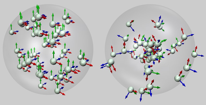 Left: Random mode, right: Surface with a spherical volume.
Here you select how the clones are placed in the volume. With Random, the clones are distributed completely randomly within the volume. The Surface mode first places the clones on the surface of the object and aligns their Z-axis in the direction of the surface Normal. The clones will then be randomly shifted far into the interior of the object volume against the direction of the surface Normal. As you can see in the illustration above, the objects (with their blue Z-axes) always point in the direction of their original surface position.
If you want to fill more complex volumes with clones, the Surface Volume mode is more suitable as it brings out the overall contour better: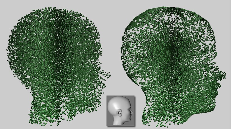 Left Mode Chance, right Surface. Head model: © Bunk Timmer
If it bothers you in such cases that the Surface mode twists the clones, use a Target Effector with a very distant target and, if necessary, a defined Up Vector.Note: Objects can be used in this context that do not work when dragged directly into the Object field (e.g., the Text Object. In these cases, it often helps to subordinate such an object to a Connect Object and use this for the clone arrangement.
In Surface mode, the two additional parameters Seed value (other values result in other random distributions) and Count (number of clones that are randomly distributed on the object surface) will be displayed. If you work with selections in this mode, the clones that are not within the selections are hidden, i.e., you have defined 473 clones to be arranged on the surface, for example, but only 34 are displayed due to a selection restriction.
Selection
If you have a point, edge or polygon selection saved using a Selection tag, you can drag the corresponding tag into this field.
All clones outside this selection will be hidden.
Enable
Here you can enable or disable cloning restricted to Selection tags.
Restrict to brush selection
This option restricts the clones to a currently active selection.
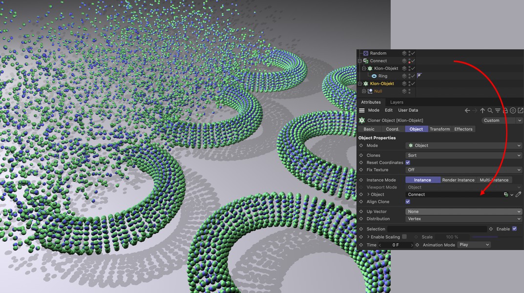
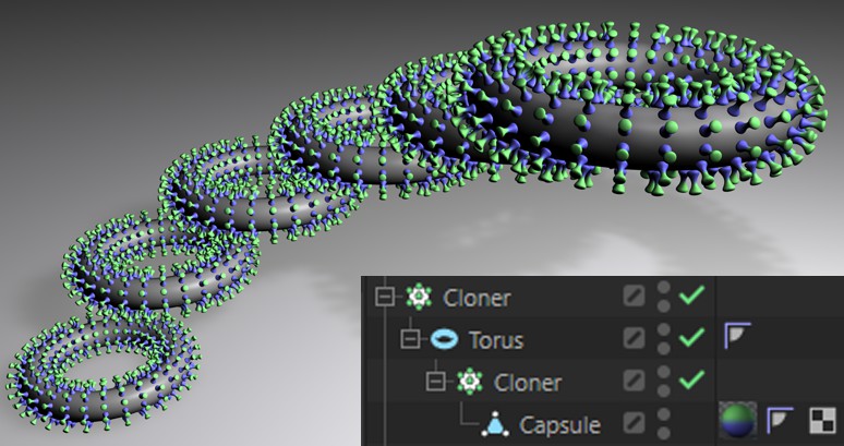
What is happing in this scene? The upper Cloner object (in Grid mode) clones a ring several times in a grid pattern. The Cloner object was then made a Child of a Connect object, which means that all rings will be internally regarded as a single object. This makes it possible for the lower Cloner object (in Object mode) to arrange spheres on the surface of the rings, i.e., on the entirety of the clones.
In addition, the Random Effector (tab Fallfoff: Shape Linear) ensures a random distribution of the clones in its effective zone.
Enable Scaling
Sometimes it is desirable to make clone sizes dependent on the underlying polygon sizes:
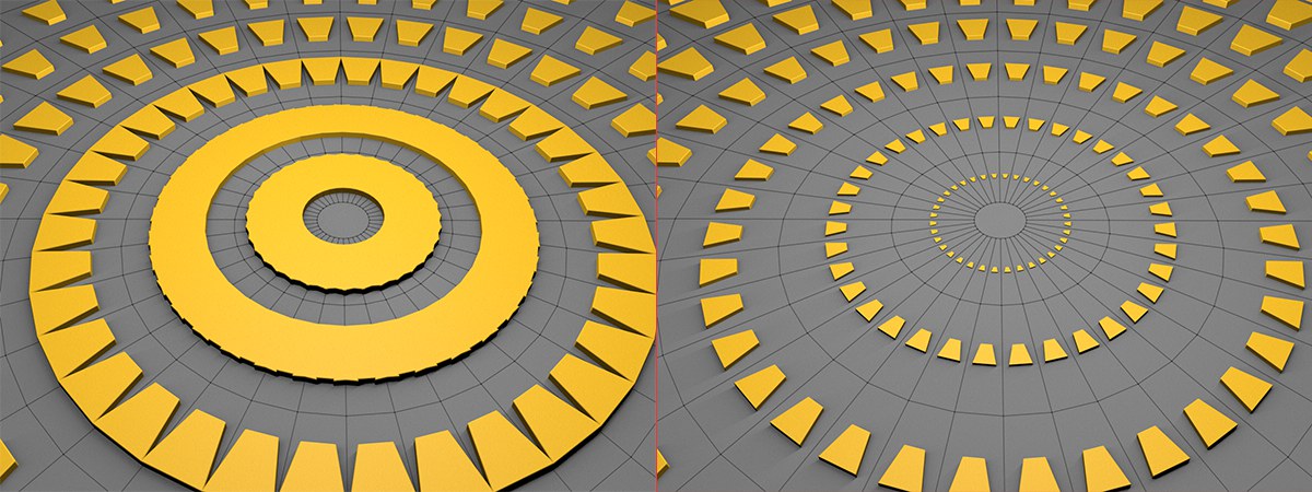 The Enable Scaling option has been deactivated on the left and activated on the right.
This works in the Distributions Point, Polygon Center and Surface. In the case of Point, all polygon sizes belonging to the point will be ascertained and the clones will be scaled accordingly.
The clone size can be defined using the Scale parameter.
You will get the best results if the object to be cloned is approximately the same size as the average polygon size. This is the only way to achieve a proportional, predictable scaling across the polygon areas with a Scale of 100 and a linear Scaling Spline. Good results will then be achieved with Scale values of around 100%.
At values of 0%, the clones will have an unchanged original size; with increasing values, clones will be scaled larger on large polygons and smaller on small polygons.
If you go below 0%, the opposite effect will occur: clones on small polygons will be scaled larger, on large polygons smaller.
Please note that when the Enable Scaling option is selected, the polygon area average will be calculated, saved and used as the basis for the individual clone sizes. This means that if you subsequently change polygon sizes and deactivate Enable Scaling and then reactivate it, all clone sizes will change due to a changed polygon area average.
Scale spline
This setting can be expanded by clicking on the small arrow to the left of Enable Scaling. This lets you control the scaling process very precisely, depending on the polygon size. Plot the polygon size on the X-axis and the scaling size on the Y-axis.
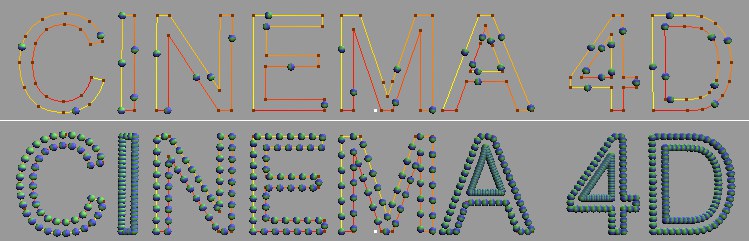
Splines
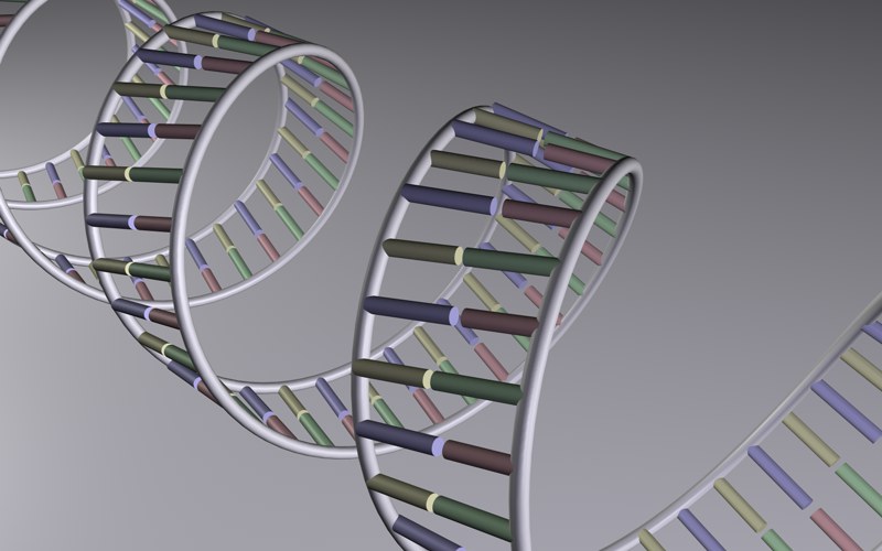 Simplified DNA strand using 2 helix splines, the base pairs are formed by clones.
If you use the Cloner object with a spline (basic spline objects also work, of course), the clones will be arranged on this.
Do not worry about the spline type (the Cloner object offers options to make the clone distance uniform).
Please also note the Spline Effector Spline Effector, which can transform any clone arrangement steplessly to a spline.
Aligning clones
The activated option ensures that the clones follow the course of the spline tangentially with their Z-axis. Otherwise, the orientation of the clones will be adapted to the world coordinate system.
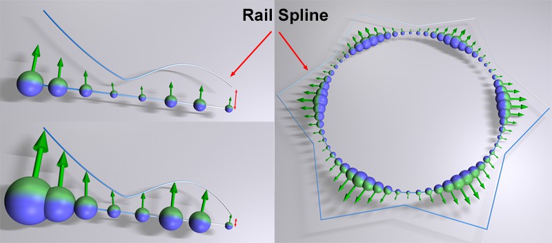
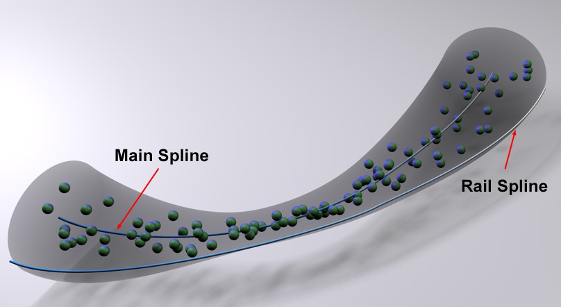
Rail
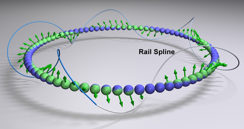 The clones will be aligned with the Rail spline. Target deactivated.
You can drag a spline into this field. The clones will then align themselves with their Y-axis (if the next option Target is activated, otherwise as far as possible) to the corresponding position of the Rail spline. What is the corresponding position? This depends on the position of the clone on the spline (the one on which the clones are lined up). If the clone is at the start of the position spline, it will also point to the start of the rail spline; if it is at the end, it also points to the end and in between accordingly.
Ensure that the main spline on which the clones are lined up is sufficiently subdivided. For straight splines consisting of only 2 points, it may be necessary to set Interpolation to Uniform or Natural and define a corresponding Points.
Target
Deactivate this option if the clones should align themselves freely on the railspline. Otherwise, their Z-axes are tangentially linked to the main spline.
Size
 Various size effects. Note the different distances between the spline starting points on the left and their effects on the clone sizes.
If the Rail Spline should have an additional influence on the clone size, use this option.
The variable spline point distances are used here to scale the clones. Make sure that the first point of the main spline and railspline are relatively close to each other. The distance between these two points defines the general size distribution of the clones. If the distance corresponds approximately to the clone size, the spline distance defines the other clone sizes relatively precisely.
Incidentally, the first clone always has the original size of the object to be cloned.
Distribution
Here you can define how the clone distances should be realized on the spline:
- Count: A total number of clones will be generated using the Count parameter to the right. The clone distances on the spline are not constant, but depend on the spline interpolation (e.g., Natural, Uniform, Adaptive). This is undesirable in most cases and can be switched off with the next two modes.
- Step: Use this mode and the Step parameter next to it to define the real clone distance along the spline. The spline will be completely filled with clones.
- Even: Here again you define a clone number using the Count parameter. The clones will be arranged at exactly the same distance from each other along the spline.
- Spline points: A clone will be arranged on each spline point without any further setting options.
- Axis: On the spline object axis.
- Group 1,2,3,4: If a MoSpline is cloned, these 4 options will be displayed. You can find details on the L systems here.
Per segment
 Deactivated at the top Per Segment, activated at the bottom (with Even = 50 in each case).
Depending on whether the defined clone numbers or increments are to apply per complete spline or separately for each of its segments (each segment is then regarded as a single spline), check this box.
Smooth Rotation
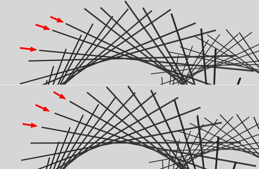 Smooth Rotation deactivated at the top, activated at the bottom (long cylinder cloned on a helix-shaped spline).
If there are irregularities as shown in the image above, which can be the case especially for splines with few defining points, you should activate this option, which leads to a more exact angle calculation of each clone.
However, undesirable side effects may occur in special cases:
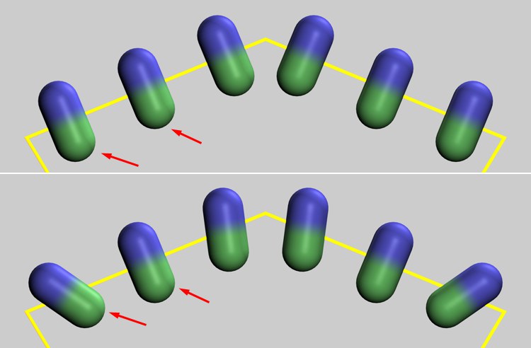 Smooth Rotation deactivated at the top, activated at the bottom.
The two marked clones are located on a straight spline section. If this option is activated, the clones will be rotated continuously, which will prevent tangential alignment (which is possible if the option is deactivated).
Offset
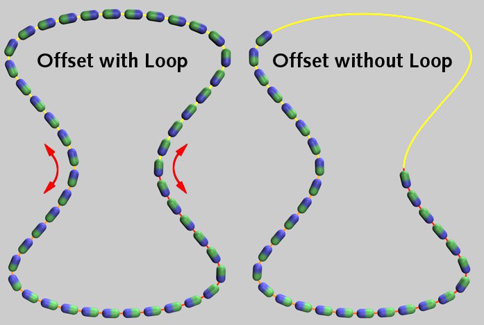
A spline always has a start (in Point mode: yellow end) and an end (red end). If the offset = 0, the clones will start at the beginning of the spline and run to the end of the spline. If you now increase the offset value, the first clone (and all subsequent clones) will move a little further. If the Loop option is activated, all clones will simply move along the spline in the loop. If the option is deactivated, however, the clones that extend beyond the end of the spline will be deleted.
In this context, note the parameter Speed, which causes all clones to cycle when the animation runs if the value is not 0 (you then do not need to set Offset keys).
Values less than 0% and greater than 100% are possible.
Offset Variation
You can use this value to introduce small irregularities into the otherwise perfect clone spacing.
Start/End
Limits the clone distribution along the spline.
Loop
For values of Offset (see above Offset) and Speed greater than 0, clones arriving at the end of the spline are deleted (Loop deactivated) or seamlessly re-inserted at the start of the spline (Loop activated).
Loop should always be activated if you want the clones to circle or run along the spline indefinitely.
Rate
Velocity works in principle like Offset, but you don't have to set any keys, the clones will move automatically when you play the animation. The parameter then defines the distance covered by the clones per second. In this context, please note the Soft Rotation option (see above) if jerky movements occur.
Rate Variation
This lets you assign a different (random) speed to each clone. If the variation is large enough (as is so often the case, values less than 0 and greater than 100% are possible), individual clones will also move backwards!
Random Seed
The starting value affects the random distribution of the velocity. Other starting values correspond to other coincidences.
Volume Spread
 You can use the volume area to make clones accurately follow a tubular volume.
If you use a Rail Spline, it can also define a volume within which the clones will be distributed. The spline point distances of both splines are used for this purpose, and this distance represents the radius around the main spline within which the clones will be distributed when the Volume Spread is set to 100%. At 0%, the clones will lie exactly on the main spline.
This is probably the simplest method for roughly following a set of objects along a spline without using particles (define a Velocity greater than 0). Imagine, for example, red blood cells in a vein.
Particles
Particles can be used as positions or matrix systems for cloning any other objects. In this way, any polygon objects or groups of objects can be attached to the positions of simulated particles, for example. Depending on the particle system used, there are slightly different options and procedures. You will therefore find explanations for the use of each of the three different particle simulation systems below.
- Standard particles: The current Simulate system introduced with Cinema 4D 2024.4.
- Legacy ParticlesGenerated by particle Emitters of older Cinema 4D versions
- Thinking ParticlesParticles generated by the XPresso-based Thinking Particles system.
Standard particles
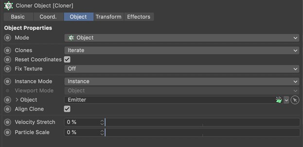
The new particle system introduced in Cinema 4D 2024.4 works with various emitter objects that add particles to special Particle Group objects. It is therefore also these Particle Groups that you need to assign in the Object link field. Alternatively, the Cloner object can also be sorted directly under the Particle Group in the Object Manager. In any case, the object that is to be cloned to the positions of the particles must be a Child object of the Cloner object. The following illustration shows these two usage options. If the same objects are to be cloned to the positions of particles from different Particle Groups, you can use a particle Multi-Group and link these in the Cloner object.
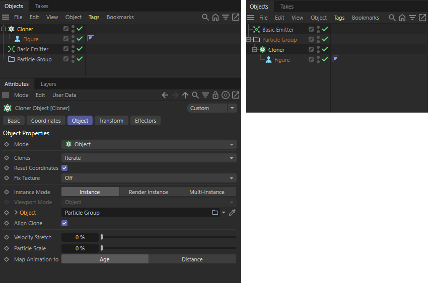 On the left, the link between particles and an object to be cloned was created via the Object Link fFeld on the Cloner object. The setup on the right has the same effect. There, the Cloner object is used directly under the corresponding Particle Group. The Object link can remain empty in this case.
As an alternative to using the Cloner object, a Redshift Object Tag can also be used on the Particle Group. There is also the option of linking a geometry to the particles and having it rendered instead of the particles. However, the options for controlling animations and stretching the particles along their direction of flight are missing.
Aligning clones
If Align is activated, the cloned object will be aligned according to the particle axis system. This should be desirable in most cases, as the axis systems of the particles can also be individually aligned and controlled within the particle simulation (see also the following figure). The rotational movement of particles can also be transferred to objects in this way.
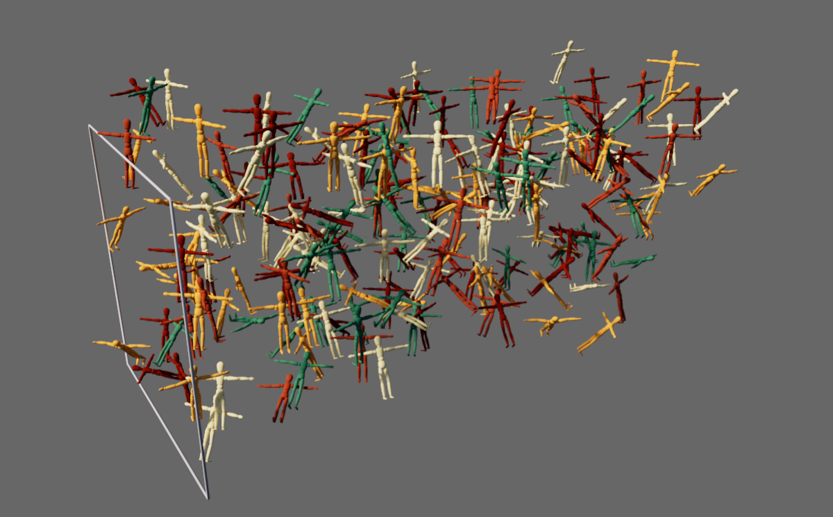 The individual alignment of the particle axis stems can be transferred to the alignment of the cloned objects.
Velocity Variation
If you want the clones to stretch in the direction of the velocity vector, you can define this here. The stretch is proportional to the particle velocity. Higher particle velocities therefore result in greater stretch than lower particle velocities with otherwise the same velocity stretch.
The following video gives an example of this effect. There, small cubes were cyclically accelerated and decelerated. In conjunction with a large percentage value for the velocity stretch, the cubes deform into quads. The supporting color change was realized by a Color Mapper Modifier of the particle system, which adjusts the colors of the particles synchronously to their velocity.
Particle Size
The particles have size information that can be defined at the Emitter or via the various particle modifiers using the Radius value. This radius is also used for uniform scaling of the objects that are cloned onto the particles. This size can be individually adjusted for cloning using the Particle Size setting. The following video shows an example of the transfer of variable Radius properties of the particles to the cloned geometries.
Use cloned objects with materials
Colors and alpha strengths can be transferred directly to individual particles via Emitters or special Modifiers. This color information is also automatically transferred to the objects that are duplicated onto the particles with the Cloner object. However, the moment you assign materials to the Cloner object or the cloned objects, this color will be overwritten. However, you can output the original particle color via a Color User Data Node in any material and combine it with any material properties.
Use the Presets ... button on the Color User Data Node and then select MoGraph/Color in the context menu.
Please note that the alpha information of the particle colors cannot currently be ouput via the MoGraph colors.
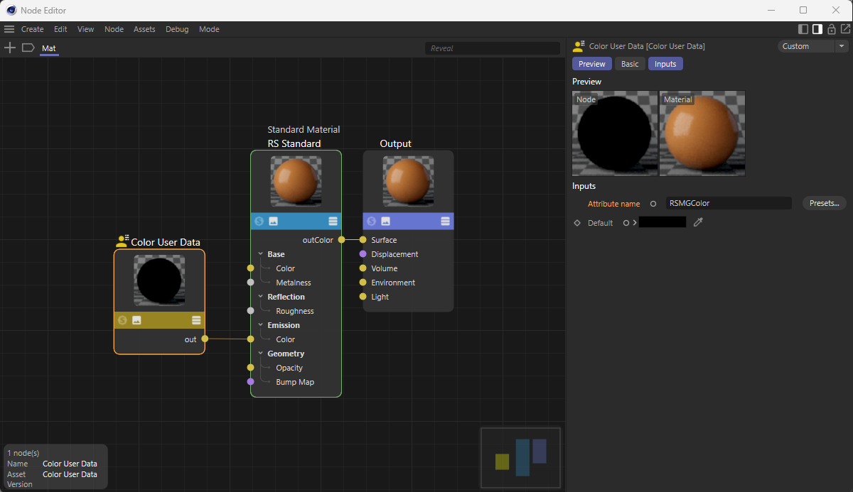 Here, the color information of the MoGraph clones will be read out and applied to the color of the emission.
Animation Relative to
The Cloner object can also be used to bind objects to particles that have their own animation in the form of keyframes. The playback of these animations can be synchronized with the properties of the particles using this setting:
- Age: The Age property of the particles shows the elapsed lifetime of each particle measured in frames, but can also be adjusted individually for each particle using modifiers. An existing animation on the cloned objects progresses at the same speed as the Age change on the particles. This usually results in the animations being played back at the same speed as they were originally created as keyframes.
- Distance: In this mode, the speed of the particles plays a role, as the distance traveled by the particles is used to control the playback of the animations. Slow-flying particles cover shorter distances in the same periods of time. This results in slower animation playback compared to fast-moving particles. The Distance per Second value can be used to define a reference value for converting the distance to a time value. The default setting of 100 cm means that one second of the animation of the cloned object is played in the time span in which a particle covers the distance of 100 cm.
The following video shows wheels cloned onto particles. These wheels were animated using two simple, linearly interpolated keyframes to complete a full rotation within 60 animation frames. You can clearly see how the rotational speed of the wheels varies depending on the velocity speed of the particles. The Distance setting on the Cloner object was therefore used here.
Distance per Second
This setting is only available for Map Animation to Distance. In the timespan in which a particle covers the distance defined here, one second of the animation will be played for the cloned object.
Legacy particles (the standard particle system before version 2024.4)
If you use the clone object with a Cinema 4D emitter, a clone is created for each particle. This and the numerous effectors give you far more options than the Cinema 4D particle system offers on its own.
Aligning clones
If Align Clone is activated, the clone will be aligned with its Z-axis to the particle velocity vector, which leads to tangential behavior along the particle path. To do this, the Tangential option (Particles tab) must be activated in the Emitter.
Velocity Variation
If you want the clones to stretch in the direction of the velocity vector, you can define this here. The stretch is proportional to the particle velocity. Higher particle velocities therefore result in greater stretch than lower particle velocities with otherwise the same velocity stretch.
Particle Size
In the emitter, you have the option of using the End Size parameter (see Emitter ) to realize continuous particle growth. The particle size here in the Cloner object is simply a multiplier for this.
Particles (Thinking Particles)
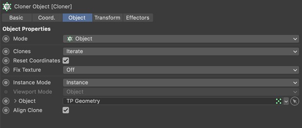
The Thinking Particles particles also work, of course. To do this, drag and drop the corresponding Thinking Particles group from the Thinking Particles settings(Simulate / Particles (legacy) / TP settings) into the Object field. Clones will then be created for the particles.
Include Sub-Groups
If the option is enabled, particle subgroups (as they are arranged in the Thinking Particles settings) of the group in the Objects field will also be included.
Behavior
You have two options here:
- Standard TP: Corresponds to the normal behavior of the Thinking Particles, except that the clone size can be varied using the Particle Size parameter. Particle Size is a multiplier for the Dimension parameter of the (for example) P Storm Node.
- TP Stretch: In this mode, clones can be scaled along the velocity vector using the Velocity Stretch parameter. The Particle Size parameter can also be used to define the clone size. Particle Size is a multiplier for the Dimension parameter of the (for example) P Storm node.
Linear Mode
In this mode, the objects that are made child objects of the Cloner object - starting from the origin of the Cloner object - will be arranged in a row, which can also have an arc shape. Each clone will be moved, rotated or scaled a little, depending on what you have defined under Position, Rotation and Scale further down in the dialog.
Clones
This mode primarily decides the order in which several objects subordinate to the Cloner object should be cloned.
The following modes are available:
Iterate
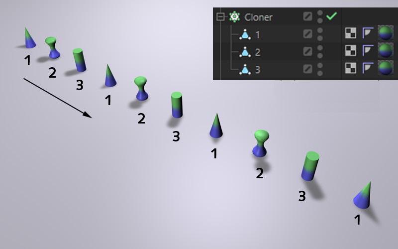
All objects directly subordinate to the cloner object will be cloned one after the other, as they are arranged in the object manager, from top to bottom and then from the front again.
Random
All objects directly subordinate to the cloner object will be used in a random distribution to generate the clones. A Seed value parameter will be displayed in each case, which can be used to vary the random distribution.
Blend
This mode has two functions: You can blend between parametric basic objects with different parameter settings, as shown in the following example:
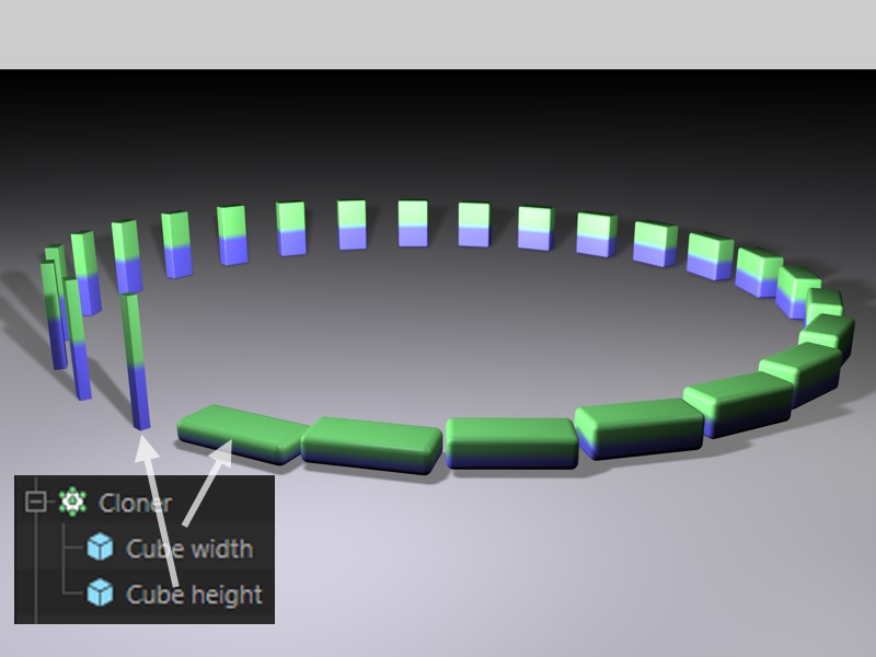
Here, two parametric cubes were cloned, each with different parameter values (here Size, Rounding Size). The Cross Blend mode ensures the interpolation of the object parameters. It can, of course, also be cloned using more than 2 subordinate objects. The parameters will then be interpolated according to the sequence in the Object Manager. Please note that the basic parametric objects must be of the same type (otherwise there will be no parameter interpolation). Parameters that cannot be interpolated, such as options or similar, cannot be changed continuously; the transition will then b abrupt.
The Blend mode can also be used to blend between polygonal objects with the same number of points (Structure Manager).
Examples
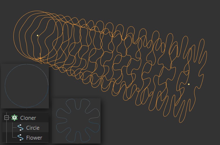
The Blend mode can also clone between spline shapes of different splines. This works best if both splines have approximately the same number of points.
Since light sources also be cloned and their colors or any other parameters blended, interesting effects can be created:
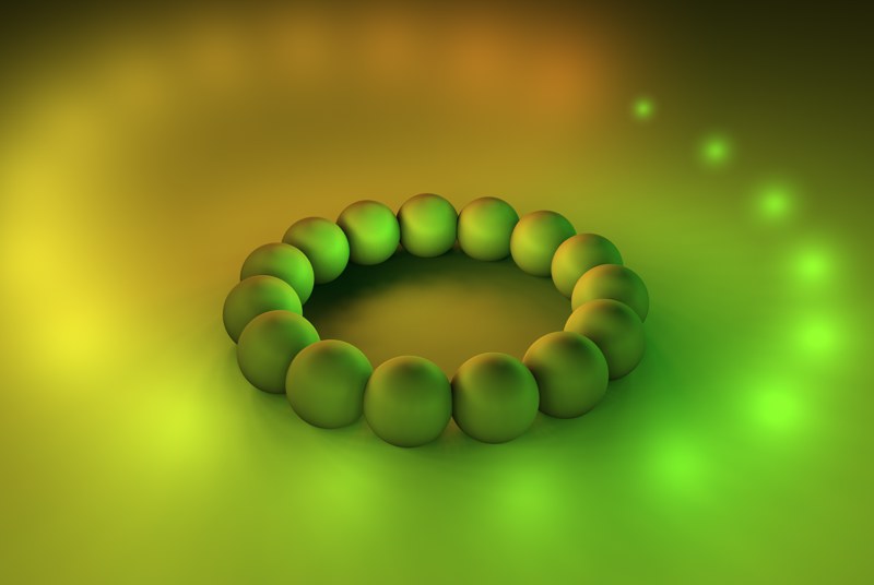 In addition to the color, the shadow density and the diameter of the visible light were also blended.
Here, 2 Cloner objects (each in Grid clone mode) have been subordinated to a third with Linear mode (Clones = Blend, Reset Coordinates disabled, P.X, P.Y and P.Z = 0).
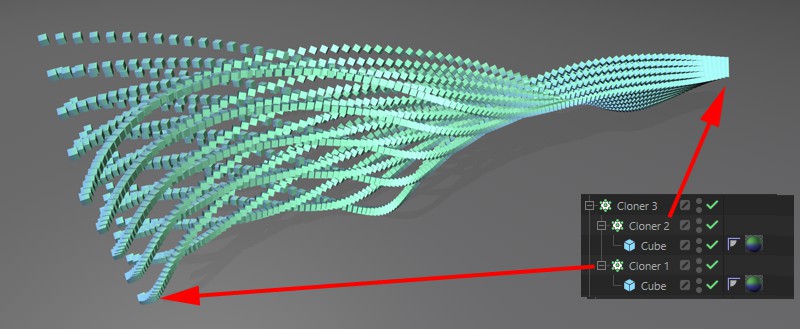 Cross-Blending also blends between different Cloner objects.
These cross blends can then be affected by Effectors (whose Modify Clone parameter must be increased). Incidentally, there are also very interesting effects in connection with animated Alembic files, e.g., if you cross-blend between 2 Alembic instances with different Offset values. Imagine an animated, cloned character (e.g., spectators in the stands) who all have different (e.g., Random Field in the Effector) animation states and therefore do not move synchronously.
Sort
The Sort mode will only have an effect when using Effectors (for those that support this, the Modify Clone parameter in the Parameters tab must be greater than 0). The corresponding Effector can then not only vary the position, size, angle, etc. of the clones, but can also vary the object sequence used for the clones, which is subordinate to the Cloner object.
Without Effectors, only the first child object will be cloned.
Example
Here, for example, a Shader Effect was used. The order of the child objects is evaluated and used accordingly for the clone arrangement (black: 1. object, white: last object).
Reset coordinates
If this option is deactivated, differences in position, scaling and angle between the objects to be cloned and the Cloner object itself will become noticeable as the clones will also be rotated, scaled or shifted.
If this option is activated, the first clone will adopt the position, scaling and angle of the Cloner object (for the XPresso fans among you: its matrix will be adopted).
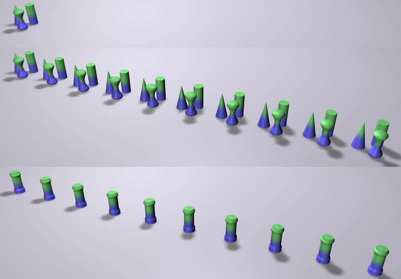 At the top are the three objects to be cloned, which have different positions, in the middle Reset Coordinates disabled, at the bottom enabled.
In addition, if this option is deactivated, position, size and angle animations of animated objects to be cloned will be adopted for the clones themselves.
Fix Texture
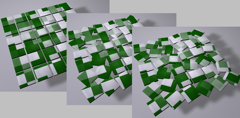 A clone arrangement with a texture in surface projection: On the left without an Effector, in the middle and on the right with the Random EffectorFix Texture set to Off or Straight.
When you texture a Cloner object, the Straight mode will define whether the texture should be projected onto the clone collection unchanged by Effectors and thus virtually pinned to the clones. If the clones are now moved or rotated by Effectors, the texture will move with them.
In Off mode, the clones will move through the texture space and will be captured by different areas of the texture depending at their respective position.
The Alternate X and Alternate Y modes do the following:
For each additional Material tag (except the first one) that lies on the Cloner object, the projection is reversed either in the X-direction Flip X or Y-direction Flip Y. What is that good for?
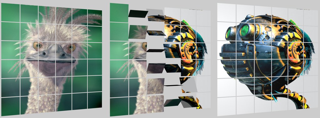 Unmirrored projection of textures. Copyright of the pictures by Peter Hoffmann (robot) and Fredi Voss (ostrich).
Suppose you project 2 textures onto such an illustrated clone conglomerate. An Effector will flip the clones and the unmirrored image (exactly corresponding to the texture) should appear on the other side. You can achieve exactly this effect by Alternating X/Y. To do this, the Cloner object must have 2 Material tags: one with Front and one with Back for Side (assuming that the clones consist of simple polygons without volume). The Material Tags must have Cubic projection defined (the texture must be projected in the Z direction).
If you have problems with this functionality, you can also use the Pin Material tag as an alternative (you can then ignore Alternate X and Alternate Y) after you have created 2 Material tags (also here: One front, one back for the side parameter) in the surface mapping for the Cloner object.
The options are useful for all projection methods except UVW, Camera and Frontal mapping.
Count
Enter the number of clones that should created here. Each clone will be moved, rotated or scaled by a certain value in relation to the previous clone, depending on what you enter further down in the dialog under P.X, P.Y, P.Z, R.H, R.P, R.B, S.X, S.Y, S.Z.
Offset
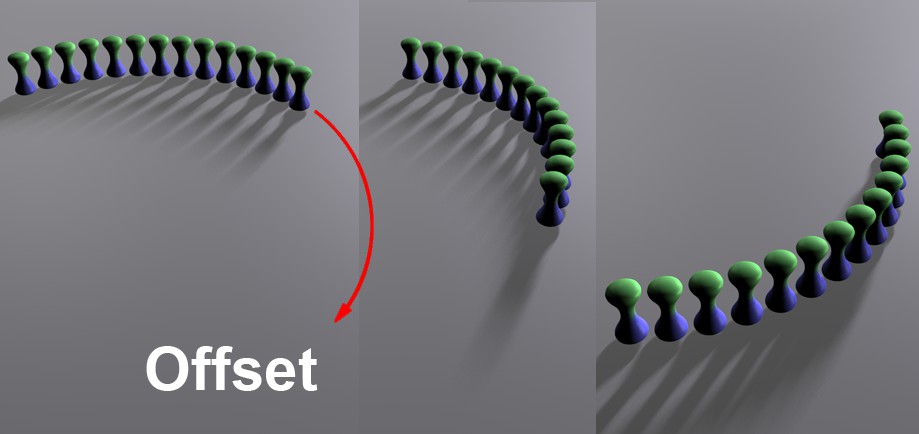
Offset will shift the first clone in the direction of subsequent clones, which will shift the entire clone series by the clone positions defined in the Offset value.
Note that this is not a continuous move, but a clone-by-clone hop forward.
Mode
With this mode, you can determine whether the following parameters Position, Rotation and Scale should apply per clone step (Per Step) or for the end clone (End Point: the values between the start and end clone are then interpolated). You can switch between the two modes at any time, whereby the values for Position, Rotation and Scale are converted so that nothing changes in the cloned result.
In this context, please also note the step effector Step Effector, which does something similar. In addition, a function graph can be used to define how this property change should take place along the clones.
Amount
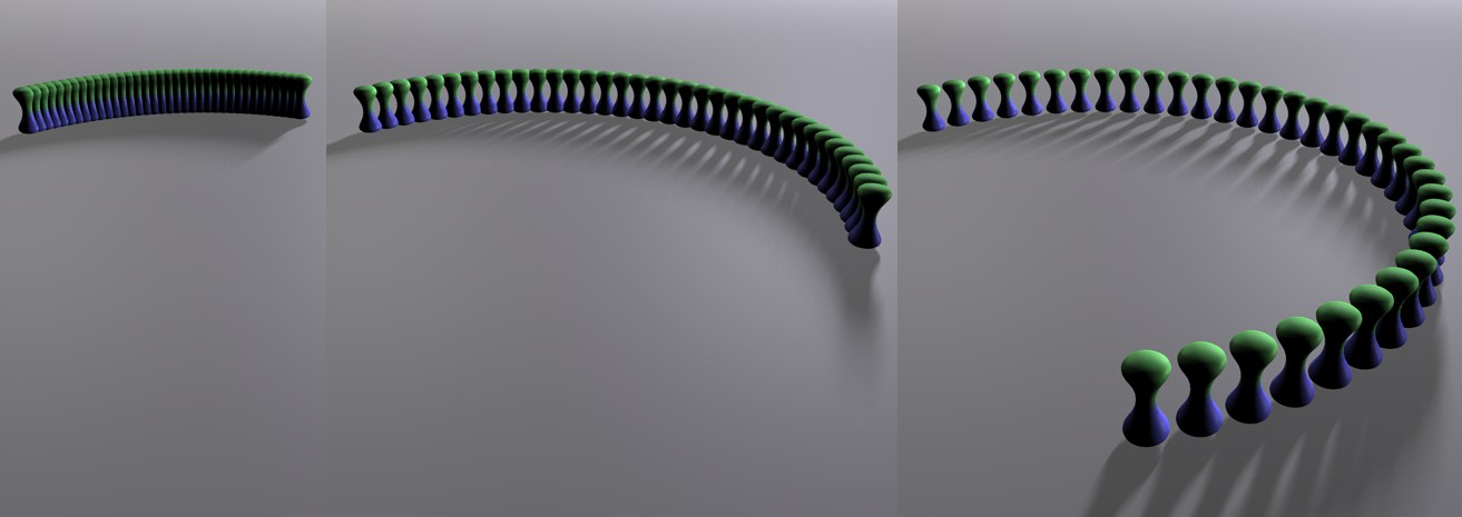 Increasing value for Amount from left to right, whereby the clones are only changed in their Position here (of course this also works with any changes in Size and Rotation).
This parameter is used to check the real effective value of the following 9 cloning parameters (position, rotation, scale) starting from 0. Mathematically speaking, Growth is merely a multiplier that acts on the 9 cloning parameters. This makes it easy to create animated growth effects.
P, R, S
You can use these values to define whether and how the position, rotation and size of the clones should be changed for the next clone.
If you are using the Per Step mode, the values here will indicate the difference to the previous or next clone. For the End Point, this will be the difference between the start and end clone with interpolated values in-between.
You can change the position of the end clone interactively in the view using the orange handle, provided you have not entered anything in the following step parameters.
The Step functionality
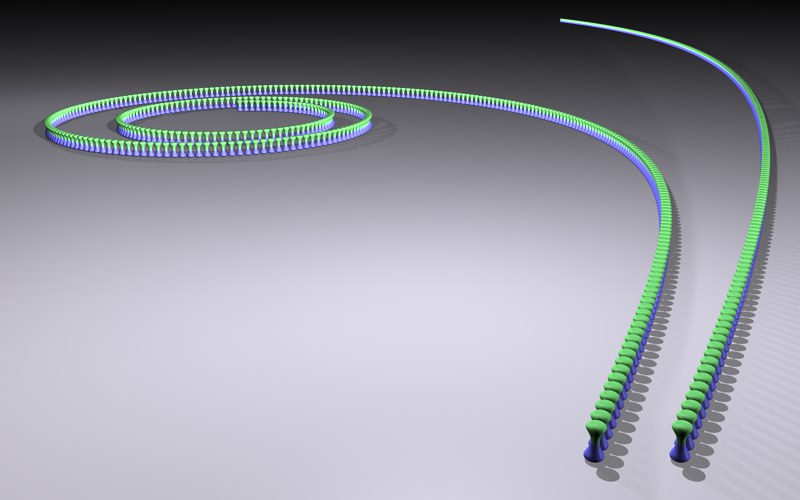
Contrary to what its name suggests, the Linear mode can arrange the clones not only in a straight line, but also in a curved or spiral arrangement. You can define this using the following Step parameters.
Step Mode
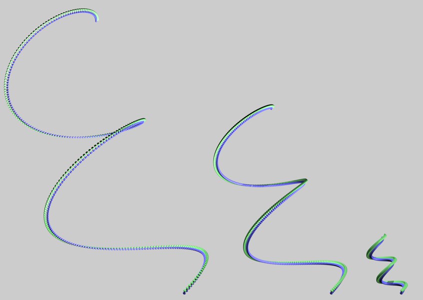
 From left to right the Step Modes Cumulative and Single Value.
Use the Step Mode to define whether the rotation change should increase evenly from clone to clone (Single Value) or steadily between the first and last clone starting from 0 (Cumulative). In the latter case, spiral cloning will result.
Step Size
 Step Size decreasing from left to right (the spiral shape is created by angles in each of the three angle fields under Step Rotation).
This reduces the step distance between the individual clones, which is tantamount to scaling the entire clone conglomerate (not the clones themselves!) starting from the origin of the Cloner object.
The Step Size can also be used for the animation of telescopic rods moving in and out (the Growth parameter is not suitable for this, as the rod diameter will also change):
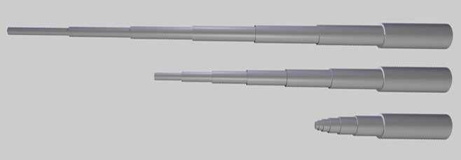 Telescopic Poles with varying Step Size and Cumulative activated for the Step Mode.
Step Rotation
Use the three following rotation input fields to define the curvature of the clone line. Values of 0 will result in no curvature at all, while increasing values will produce a correspondingly greater curvature.
Step Rotation
Values for at least 2 of these parameters lead to spirals as in the image above, while values in only one field lead to an arc perpendicular to the respective axis (1. Field: Y-axis, 2. Field: X-axis, 3. field: Z-axis of the Cloner object).
Radial mode
In this mode, the Cloner object's Child objects will be placed in a circle around the center of the Cloner object.
Reset clones/Coordinates/Pin Material
These functions work in exactly the same way as already described in Linear mode (see above).
Count
Use this to define the number of clones that should be arranged on the radius.
Radius
This is the radius on which the clones will be arranged around the Cloner object. The radius can also be changed interactively in the view by dragging the orange handle.
Plane
Use these options to define the level in which the circle and clones should be located. The decisive factor is the coordinate system of the Cloner object.
Align
If this option is activated, the clones will be arranged with their x-axis tangential to the circle. If deactivated the clones will be rotated with their axes to the coordinate system of the Cloner object.
Start Angle/End Angle
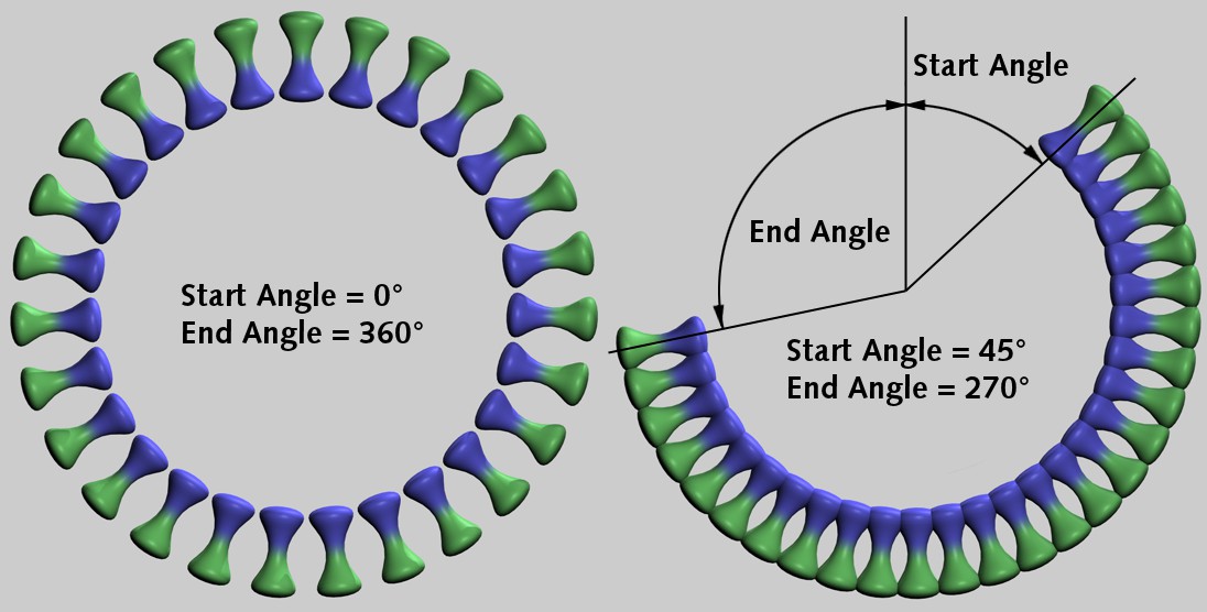
Use these two angles to define which section of the circle should be filled with the clones. Values less than 0° and greater than 360° are possible, although this can lead to overlaps.
Offset
This lets you rund the clones along the circle.
Offset Variation
If the clone arrangement is too regular for you, you can use this value to introduce random deviations from the ideal distribution.
Offset Seed
Where random values are used, there is often a Seed value. This varies the random distribution - in this case that of Offset Variation.
Grid mode
In this mode, the objects subordinate to the Cloner object will be arranged in a spatial grid. This is well-suited for grid-like effects such as:
The cloned object on the bottom-right will then be varied in rotation in Grid mode using an Effector.
You can certainly imagine the spectacular effects that can be achieved when you animate the Effector so that it passes through the grid.
As there are a large number of objects here and the editor display can therefore become very slow, the detailed settings of Cinema 4D work here:
- Editor: Display
- Display tag. The tag will be assigned to the Cloner object.
Reset Clones/coordinates/Pin Material
These functions work in exactly the same way as already described in Linear mode.
Count
Use the number to define the number of clones in the X, Y and Z directions.
Mode
Here you have the choice between:
- Per-Step: The Size parameters below refer to the clone distance (there are 2 new handles at the corners of the Cloner object; these can be used to adjust with a constant clone distance and a changing number of clones).
- Endpoint: Here, the Size parameters below refer to the dimension of the entire clone conglomerate (the two new handles at the corners of the Cloner object also work for this: they adjust the dimensions of the clone conglomerate with adjusting clone distances).
The values will be converted when the mode is switched.
Size
Use Size to define the extent of the complete grid clone conglomerate in the X, Y and Z directions. This can also be done interactively in the Viewport using the orange handles.
Form
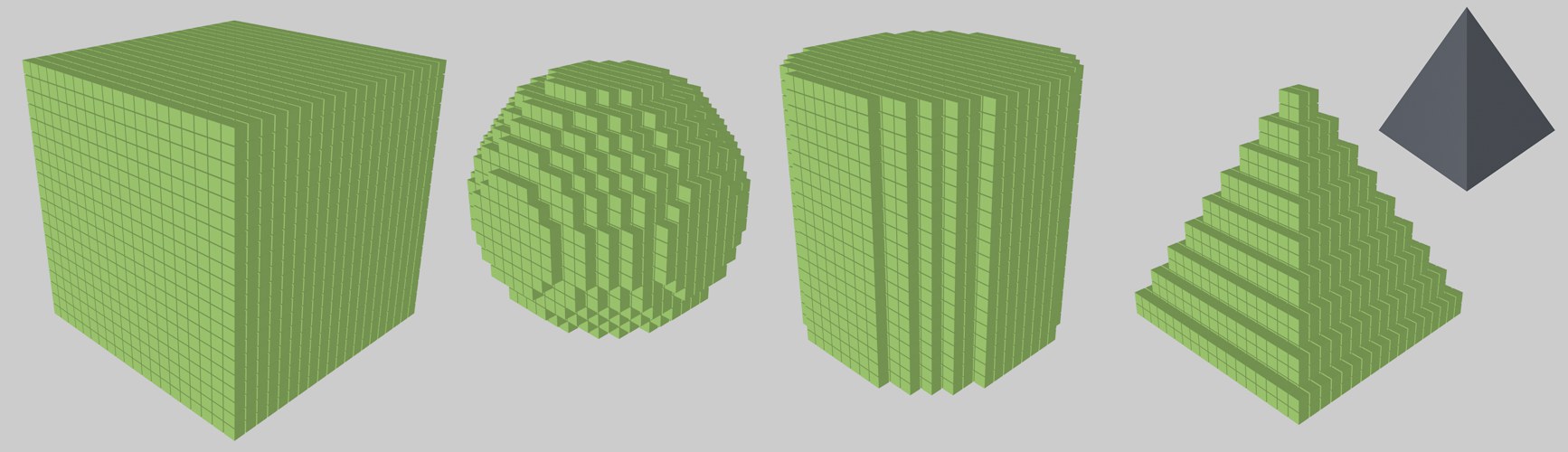 The various forms; on the right a cone was used to shape the form.
You can choose from the following shapes: cube, sphere, cylinder and any shape (Object). As you can see, the excess clones that do not fit into the shape will simply be ignored for the Cylinder, Sphere and Object.
Fill
By reducing this parameter, you can empty the inside of the shape so that gradually only the clones of the shell remain.
Object
Drag in any polygonal object (can also be a Generator), within whose volume clones are generated in the first place (this is faster in terms of calculation than if you use the Volume Effector instead, which can do similar things).
Please note that problems may occur if rows lie exactly on the surface of the object, as these may not be considered part of the volume. Then scale the object slightly.
Honeycomb Mode
In this mode, a two-dimensional grid arrangement (see also Honeycomb arrangement ), in which every second row is shifted.
In the Viewport, you will find interactive handles with which you can adjust the expansion of the honeycomb grid either in one axis (center handle) or in both axes (handles at the corners).
Orientation
Here you can define the object coordinate axis to which the honeycomb grid should be perpendicular. The axes in brackets indicate the plane in which the honeycomb grid will be located.
Offset Direction
Use this setting to define how the honeycomb arrangement will be created: for Height, every second vertical row will be shifted; for Width, every second horizontal row will be shifted.
Offset/Offset Variation
This parameter can be used to affect the shift of every second row: At 0% there will be no shift in relation to the adjacent rows; at 50% they will be centered, and at 100% they will be shifted by exactly one clone position.
The values to be defined here represent a maximum value that will be randomly varied by Offset Variation for each row to be moved.
Perpendicular Variation
This means that the row spacing of each row can also be varied randomly in the other direction (opposite the Offset direction).
Seed
As always, when it comes to random distributions, there is this parameter that provides other randomness (see also Seed value).
Count Width/Count Height
Here you can define the number of clones in width and height. Depending on the Mode, the honeycomb grid expansion (whereby the distances between the honeycombs will remain constant) or density will change.
Note that the total number of clones with a rectangular Form will be not the product of the two parameters, but almost exactly half. This is a result of what is defined for Offset Direction, the corresponding number applies to a double row that will be shifted in relation to each other.
Mode
This mode determines whether the following two parameters Size Width/Height define the Honeycomb grid dimension (Endpoint) or the cloning distance (Per-Step). Their values will be converted when the mode is changed, the result will not change the honeycomb grid.
The handles on the corners change depending on what you set here in the mode, Count Width/Height or Size Width/Height.
Size Width/Height
Define the height and width of the honeycomb grid with the same number of clones.
Form
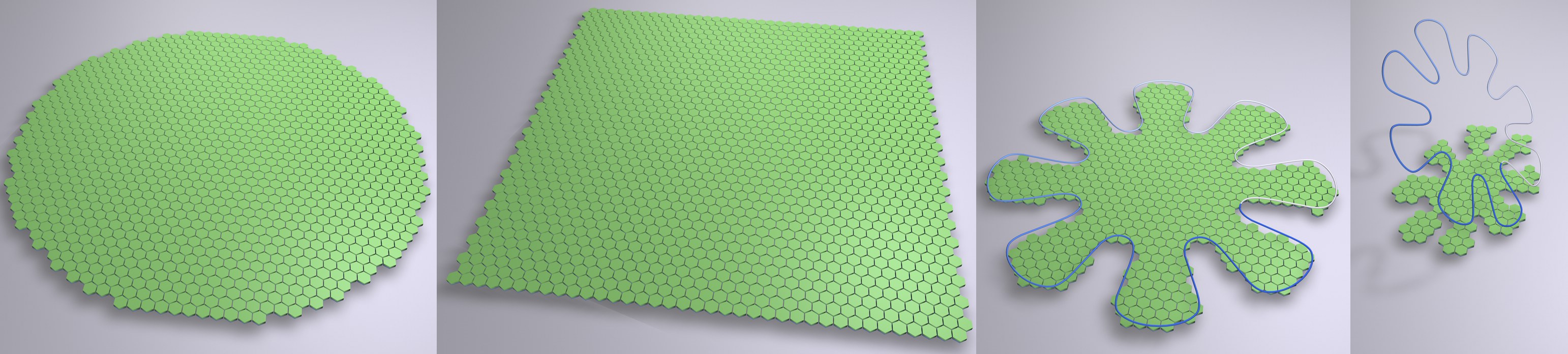 The different Form types.
As it is not always practical to create a rectangular honeycomb grid, you have a choice of several shapes. The Square and Circle are self-explanatory.
Spline can be used to create any shape.
Spline
Drag in a spline that is projected vertically in the direction of the honeycomb grid plane (see image above, right). Imagine the spline projected onto the clone arrangement in Form Square: only clones lying within the spline projection are generated.
Open splines are closed internally