Scene
Here you can select if the simulation should be calculated using the CPU or GPU. Complex calculations (dense mesh, many collisions) should be calculated using the GPU (graphics card) and only simple scenes using the CPU. With an active GPU option, the desired card can then also be selected as Compute Device for systems with multiple graphics cards.
Note also the following Limitations
If you have selected the GPU option in Device, you can select the graphics card of your system here. If several graphics cards are available, you can then select the fastest card or the one with the largest memory, for example. If there is only one graphics card, you can ignore this setting.
Here you can define the gravitation (a force in the negative -Y axis direction). Note that the Force object ![]() Gravity (the direction of its effect can be modified) can also be applied. Both will then be added.
Gravity (the direction of its effect can be modified) can also be applied. Both will then be added.
This gravity also automatically acts on particles that were either generated via a Liquid Fill Emitter or provided with a Liquid Contribution property above 0% by a Liquify Modifier.
This setting affects aerodynamic effects that can be activated in Rigid Bodies and Cloth. In their tags, you will find the two parameters Drag and Lift in the Forces tab. Increase these values so that you can create aerodynamic effects such as leaves sailing through the air or flags fluttering in the wind.
The higher the Air Density, the stronger the aerodynamic effects, while an Air Density of 0 eliminates the same. Corresponding objects then behave as if they were in a vacuum.
In the following scene, the air density is 0, 1 and 5 (from the back left to the front right).
With this setting you can slow down (slow motion) or speed up (fast motion) all effects concerning the simulation.
Please note that the simulation changes and sometimes becomes erroneous - the more you deviate from the value 1 (=real time).
Strange simulation behavior can occur in very small or very large scenes (see also Tips and Tricks), for example in an "explosion" scene.
This factor translates the Cinema 4D size ratios into those of the underlying simulation engine. Follow this simple rule of thumb:
If you have objects flying around that are predominantly 100 Cinema 4D units in size, leave Project Scale set to "100cm". If the objects are 1000 units in size, enter "1000 cm".
You only need to change this value if strange behavior, i.e., miscalculations, occur.
If you notice that there is a frame delay of 1 frame (i.e. the generator is 1 frame ahead in time) when playing a simulation with a Generator, you can activate the option here, which should improve the situation. The disadvantage, however, is that for internal reasons 1-frame delays can occur in other areas (e.g., animations). In this case you can cache the simulation and the animation, e.g., offset by 1 frame - or modify the tag's priority with the cache to Generator -100, for example (Simulation).
If this option is enabled, the simulation always runs over the entire preview frame range as defined using Preview Min and Preview: max (or interactively in the Animation palette). Disable this option to individually define the simulation length using the following two settings.
Start Frame[-2147483648..2147483647]
End Frame[-2147483648..2147483647]
Disable the previous option to define an individual simulation duration here. This is, for example, very useful if a swinging rope should collide with a character at a specific frame - at which point the simulation will begin.
Initial Memory Budget[10..100000%]
This setting is only available in the Scene Settings of a Simulation Scene Object and not in the otherwise identical Scene Simulation Settings, which you can access via .
When a simulation is run, numerous calculations are continuously performed and data, e.g. for the timely detection of collisions, is stored in the memory. Depending on the complexity of the simulation scene and the number of objects it contains, the amount of memory required for this can become relatively large, which can lead to problems during playback of the simulation. This is particularly important for scenes that contain several simulations or when simulating with hardware that has relatively little free memory.
For this reason, this value can be used to limit the amount of memory initially reserved for this simulation and its intermediate storage of data. If there is a lot of memory available on your hardware, you may be able to speed up the calculation and playback of simulations by using a higher value, as it is not necessary to repeatedly adjust or increase the amount of memory originally reserved, which may have been too small, during the simulation.
On the other hand, if the hardware has a smaller amount of memory or if several simulation scenes are used within a project, it can help to select a lower value here so that there is still enough memory initially for the other simulations in the scene.
In any case, the simulation can always independently increase the reserved memory during the simulation calculation in order to save the necessary data. However, this memory adjustment requires a certain amount of time, which can slow down the playback of the simulation (unless it was calculated as a cache).
In summary, it can therefore be said that
-
Lower value if: Generally only little free memory is available on the hardware selected for the simulation, or if several simulations are to be calculated within the same scenes.
-
Higher value if: There is a lot of free memory on the selected simulation hardware or if only a few simulation scenes and elements to be simulated are active in the scene.
The following applies to the Simulate Scene Settings: All tags, objects and connectors relevant for a simulation end up here when they are newly created (i.e. they initially have a scene-wide effect). If you later explicitly assign tags (exception: Collision tag) to a Simulation Scene object, it will be removed from the list here.
For the Simulation Scene Object: Drag here all simulation tags and objects that are to act exclusively for this simulation scene object (see also previous paragraph). The button on the right can disable these.
Here is a small example of the Pyro Simulation System.
Given are two spheres that have been declared emitters for smoke with Pyro Tags. Using the tag's Color option, the smoke of both objects can be colored differently, for example. You specify the appearance of the smoke or even the forces that should act by adding temperature or fuel in the Pyro section of the Scene Settings. There you can also change, for example, the Voxel Size, which can be used to adjust the level of detail and complexity of the entire simulation.
But what if only the emitted smoke of one of the two spheres is to be calculated more coarsely or swirled differently, for example? We would need Pyro settings for this, which we could assign individually to individual Pyro Tags or Pyro Fuel Tags.
This is exactly where the Simulation Scene object with its Elements list comes into play.
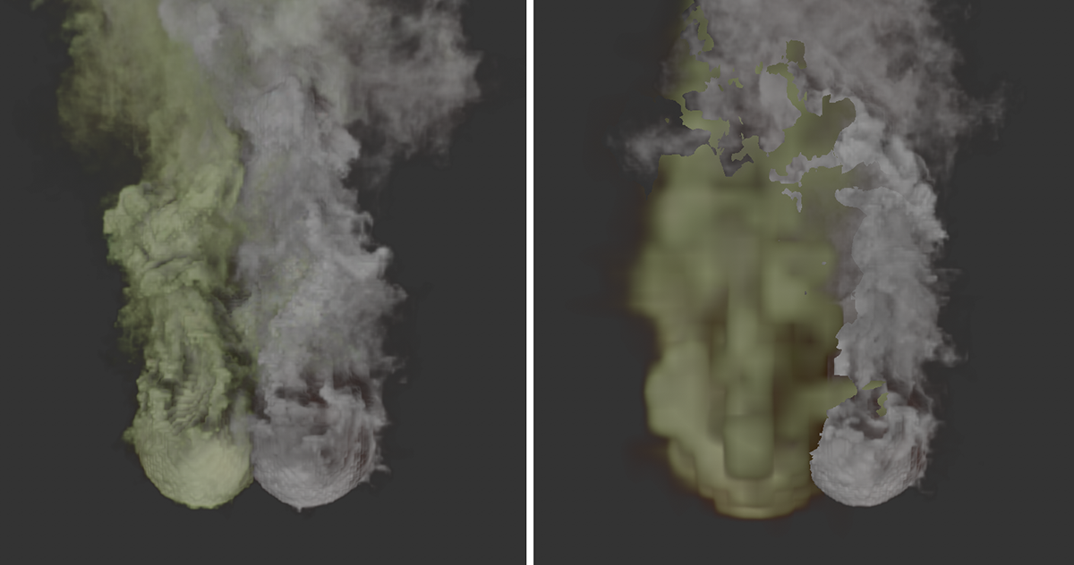 On the left you can see the initial situation. Two bullets have received Pyro tags and emit smoke. The default values from the Pyro tab of the project settings control the calculation accuracy and the calculation methods. On the right, a simulation scene object was created and the Pyro tag of the left sphere was assigned there as an element. Individual settings for the smoke of the left sphere can now be made at the Pyro settings on the Simulation Scene object. Here, for example, the Voxel Size was increased.
After calling the simulation scene, drag one of the Pyro tags to the Elements list. This creates a new Pyro object in the scene (Pyro (Simulation Scene)), which is now associated with this Pyro tag. In addition, directly at the Simulation Scene object you will now find a Pyro tab with all simulation settings, which can now be edited here individually for the linked Elements.
The already existing Pyro object remains and is from now on responsible for all Pyro and Pyro Fuel tags that have not been linked in a Simulate scene. You can recognize this Pyro object by its name Pyro (Default).
Now that individual pyro objects are available for the Pyro simulations, they can be used separately for computing and caching.
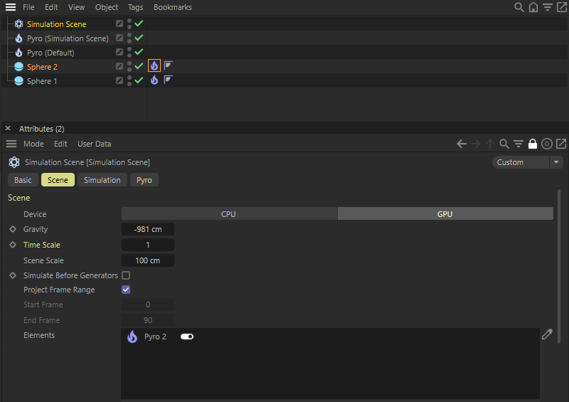 View of the objects of the scene. An additional Pyro object is bound to the Pyro tag of Sphere 2 via a Simulation Scene here.