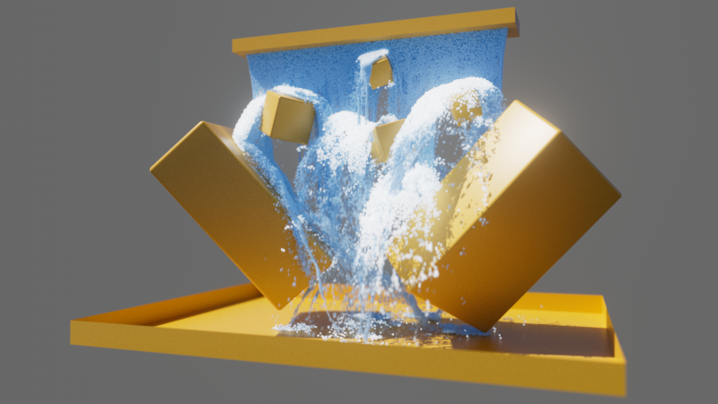
 A still image from the simulation of a waterfall with particles. The impression of flowing water was created by automatic color changes of the particles, a Flocking behavior, Gravitation and rendering with Motion Blur.
Cinema 4D 2024.4 introduces a completely new particle system that can not only process much larger quantities of particles faster than before, but also allows detailed influencing of the particle behavior. The use of logical Conditions, Groups and Modifiers plays a particularly important role here. These are new object groups that you can find - together with the new Emitter objects - in the Simulate menu. The older particle systems are still housed there so that you can continue to use your old projects. However, you should start new projects that benefit from particles directly with the new particle system, as this can now also use your graphics card (GPU) and is therefore correspondingly more powerful. You are already familiar with this principle from the other simulation systems in Cinema 4D, such as the Pyro fire and smoke simulation, the Cloth simulation or the simulation systems for Soft and Rigid Bodies.
Topics in this introduction:
Particles are often just point-like elements that can have different properties, such as colors, sizes, speeds or rotational animations. In this phase, particles are reminiscent of simple dust particles in the air, for example, which can be affected in their movement by forces such as gravity or wind. Particles are particularly interesting because we can link any other objects to them. For example, particles can also represent grains of sand, falling leaves or even complex models such as cars or people. This is made possible by the fact that the particles not only represent positions in space, but also have their own matrices that allow objects linked to particles to be scaled and aligned as required. Think, for example, of an arrow that has been shot or an airplane whose tip always flies ahead and aligns itself with the flight path.
Since both internal forces between the particles and external forces such as wind or gravity can act on the particles, it is also possible to simulate natural behavior, e.g., a herd galloping across a landscape or a flock of birds or fish. When working with very large quantities of particles, it is even possible to create massive structures without having to link objects to the particles. Think of snow or sand, for example. Since particles can also be used as center points for voxels, a Volume Builder can also be used to create polygon objects that can replicate the volume occupied by particles.
Particles can be used for a variety of abstract effects and animations without having to animate each element involved in the animation separately. The combination possibilities with the other simulation systems open up additional options that could previously only be implemented with great effort or via external plug-ins.
Particles can be conveniently created and operated using special objects in the Object Manager, all of which can be found in the Simulate menu of Cinema 4D. These particle elements are already sorted into logical groups, the meaning of which we will discuss in the following section.
The video above shows the simulation of a stylized waterfall with simple particles without assigned geometry. The color changes were also calculated automatically within the particle simulation.
To keep the files small and manageable, they do not contain any caches of the particles or the other simulations used. To enable smooth playback and rendering with Motion Blur, you should therefore calculate the caches for the Particle Groups contained. You will find a Calculate Object button in the Cache tab of the Particle Group objects.
Particles are always helpful if you want to animate complex, abstract structures or if you want to animate a large number of objects. The possibilities of particles go beyond those of MoGraph, for example, because the number of particles can be varied at any time based on rules. In addition, the simulation of physical behavior is practically already built in here. Particles can have individual speeds and directions of flight and react to their environment and other particles. Here you can find an example of this:
 A still image from the simulation of a waterfall with particles. The impression of flowing water was created by automatic color changes of the particles, a Flocking behavior, Gravitation and rendering with Motion Blur. A still image from the simulation of a waterfall with particles. The impression of flowing water was created by automatic color changes of the particles, a Flocking behavior, Gravitation and rendering with Motion Blur.
|
In addition to this rather typical aspect of particle animations, particles can also be mixed and interact with other simulations. For example, particles can also emit flames and smoke with the help of the Pyro simulation or influence the weighting values in a Vertex Map Tag. An introduction and further examples of the use of pyro simulations can be found on these pages.
Here you will find some particle examples:
| In this example, particles fly over a plane and the trajectories are traced by automatically fading Vertex Map weights, which then control the areas where aPpyro emitter produces smoke. |
| Here, the collisions of the particles with a plane are recorded in a Vertex Color map, which is used to change the displacement and the coloring at the "impact points" of the particles. |
Although the particles themselves have no mass and therefore cannot directly move other dynamic objects in the event of a collision, this is also possible with a little trick. Here, for example, we use a Field Force object that can be used to convert the velocities of the particles into forces that can set the plane suspended by a hinge in motion.
| Here, the particles act indirectly via a Field Force object on the articulated plane and cause it to vibrate in the event of a collision. |
In addition, the particles within the Particle Groups are managed like normal points. This means that they can also be deformed with deformers or, for example, converted into organic shapes in combination with a Volume Builder. You can find examples of this here:
| Particles can not only elastically collide with other objects, but also stick to them or slowly slide off. In this example, we use all these options in combination with a Volume Builder to represent a liquid. |
Particles can also appear automatically elongated, for example, depending on their speed. You will find the corresponding options directly on the Volume Builder.
| Here, the particles were simply emitted in a straight line, but then bent along a spline using a Spline Wrap deformation object. In addition, a MoGraph Tracer traces the trajectories of the particles and makes them visible as simple splines. |
In this scene, note that a cache must first be created for the Particle Group so that the deformation along the splines can be calculated (see Cache tab of the Particle Group. Use the button for Calculate Object there).
As an alternative to using a cache calculation, the Spline Wrapper can also be placed directly under the Tracer in order to deform the traced trajectories of the particles along the splines.
As already mentioned, the particle system offers various options to control the creation and properties of the particles. Let's take a look at these elements, which you can find in the Simulate menu of Cinema 4D and which appear as normal objects in the Object Manager when called up.
If you are directly interested in certain categories, you will find the links for quick access here:
An emitter determines the location of particle formation and which properties the particles are to be given at the beginning. These are often their initial direction of flight and speed or their color and size. Various emitters are available, depending on where the particles are to be formed:
 In each of these examples, 10,000 particles with a low propagation speed were chosen. From left to right, a Rectangle, a Circle, a Cube and a Sphere were used as emitter shapes.
 Two examples of the use of a Mesh Emitter. On the left, the slopes of a landscape have been converted to a Vertex Map, which is used to create particles on the landscape. On the right, a wavy polygon strip emits particles. Here, too, the distribution of the particles has been varied using a Vertex Map. In addition, sizes and colors have been varied. Separate modifier objects are used for this.
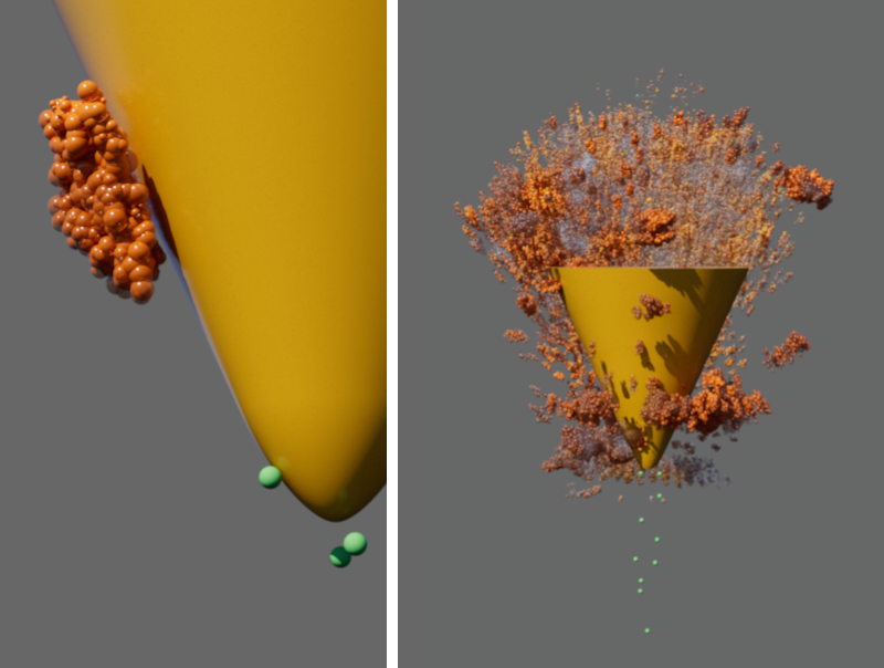 In this example, green particles hit a cone from below and collide with it. These collisions are used as triggers for a Reproduce Emitter, which replaces each colliding particle with many new particles.
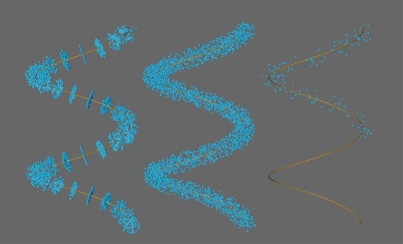 Particles can be generated, for example, in fixed sections, within a tubular volume or only on a part of the spline.
For all Emitters, it should be noted that they only define the Conditions that ascertain the location and initial properties of the particles. As soon as a particle has been generated, it no longer has a connection to the Emitter. It is therefore no longer possible, for example, to group objects that are to be used instead of particles directly in the Object Manager under an Emitter. Instead, all particles are managed in special Particle Groups. If you have already worked with the older Thinking Particles system, you may be familiar with this principle.
For this reason, an additional Particle Group object will automatically be created when the first Emitter object is called. All generated particles will then be managed in this group. It is also these Particle Group objects that will automatically be assigned a Redshift Object Tag in order to be able to render the particles directly as visible objects. Alternatively, these Particle Groups can also be used via MoGraph Cloner or Matrix objects to place axis systems or any other objects. It is also possible to use these Particle Groups together with the voxels of a Volume Builder object.
Particle Groups are required to manage the particles created by emitters. In addition, the appearance of the particles in the views and also the caching of the particles can be controlled via groups. At least one Particle Group is always required in the scene if you want to work with particles. Therefore, the first Particle Group object is also created automatically when you call up your first Emitter object.
Groups can also be created manually via the Simulate menu or sometimes directly, e.g. via Create Group buttons on the emitters.
Groups offer different shapes that can be used to display the particles in the viewports. Depending on the selected shape, the orientation or flight direction of the particles can also be read from it. These shapes cannot be rendered in this way, but by assigning a Redshift Object Tag, different shapes can also be selected in a Mode menu in the Particle section, which can be used for rendering. Without this tag, the particles are only rendered as spheres by default. These are the different display shapes on a Particle Group:
 Here different Draw Modes have been used on the Particle Group object. From left to right, these are Dots, Arrows and Ticks.
 Here different Draw Modes have been used on the particle group object, with Lines on the left and Handles on the right
In addition to the displayed shapes, the Radius of the particles can also be drawn as a circle using an option (see figure below). The radius represents the size of each particle. This is one of the properties that can be set directly on the emitter.
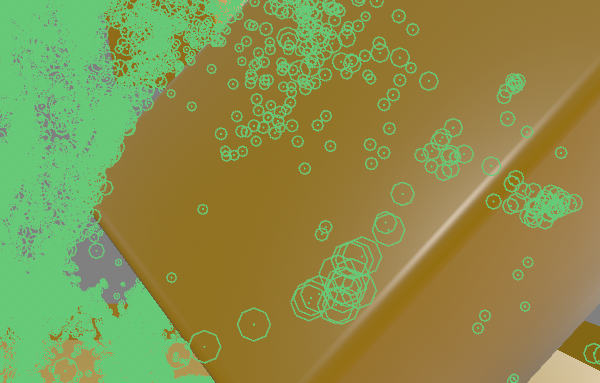 Here, the Dots display was combined with the Draw Radius option in order to be able to examine the particle size without rendering.
In addition to these more formative settings, the color of the particle display can also be influenced at the group. The emitters already give the particles colors when they are created, but these can also be replaced for the display in the views via the groups. This can be helpful if you want to directly recognize which particles are managed in which group when using many groups via the coloring of the particles. The color visible in the rendering can also be specified via materials that you assign to the groups.
 Here, the setting None was used for the Override Mode. The particles receive their colors directly from the emitter (shown on the left) or through special modifiers, such as the Color Mapper object. This also allows individual color gradients to be implemented, such as in the image on the right.
 On the left-hand side of the image, the Constant setting has been used and a new color has been selected in the group, which now recolors the original green particles. The right-hand side of the image shows the coloring in Direction mode. The particles are colored according to their direction of movement. Movements along the X-axis are colored red, along the Y-axis green and movements along the Z-direction blue.
Particle groups are at the heart of the particle simulation, as they contain the particles and make them available to the functions that define forces or assign colors, for example. These objects can be found in the Conditions and Modifiers groups discussed below. If, for example, you want to apply gravity to particles that are managed in different groups, you can also use Multi Groups. Several groups of your simulation can be specified in these. Multi Groups then automatically make all particles of the listed groups available without you having to change the existing group division of the particles. You can find an example of how to use them in the section on Modifiers.
As already mentioned, particles are initially only visible as spheres in the rendering and are therefore often only used as placeholders, e.g. for other objects. Shapes can be assigned to particles directly via a Redshift Object Tag, for example, which you can assign to the Particle Group in the Object Manager (right-click on the Particle Group and select Render Tags/RS Object). You will find a separate Particles category on this tag, in which you can choose from various display options:
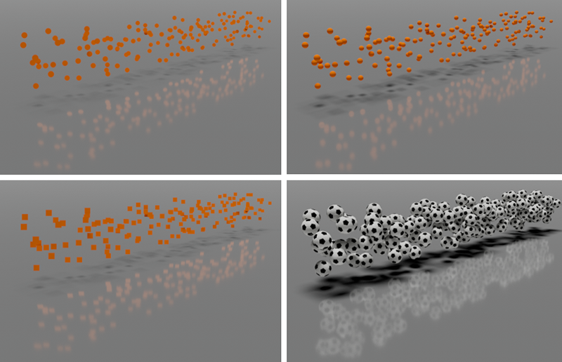 The left column shows the 2D shapes Point Instances (top) and Quad Instances (bottom). The top right shows Sphere Instances for comparison. Notice how the shading of the particles and their shadows are more detailed. Using Optimized Spheres would look identical. On the bottom right, a soccer ball object was called from the Asset Browser and assigned as a Custom Particle Shape using the Redshift Object Tag.
As can also be seen in the above illustrations, the colors of the particles are automatically adopted for the display of the standard shapes on the Redshift Object Tag. You only need to create a Redshift material if you want to use your own shapes or individual materials, e.g. with customized reflections or transparencies. We will therefore take a look at how you can evaluate the color properties of the particles within a material.
In addition to using the Redshift Object Tag, a MoGraph Cloner object can also be used in Object Mode, for example, to render any objects instead of the particles. In this case, however, you should still assign a Redshift Object Tag to the Particle Groups and select the Mode Disabled so that the typical particle spheres are not rendered in addition to the cloned geometry.
The use of the Cloner object even has some advantages over the Redshift Object Tag. This means that not only can different objects be cloned randomly and in sequence onto the particle systems, but can also be controlled via MoGraph Modifiers. The Cloner object also offers options, e.g., to display an elongation of the particle shapes according to the flight speed of the particles. It is also easier to use animated objects as particle shapes in this way, as the Cloner object can automatically synchronize the playback speed of animations with the speed of the particles, for example.
You will find all information on using the MoGraph Cloner object with particles on this page of the documentation.
In general, it makes sense to save simulations as a cache before rendering. This is particularly helpful if you do not want to render directly from the start of the simulation time, e.g., the first frame from which an Emitter emits particles, but only when several simulation images have already passed and the particles have already been distributed. The same applies if you want your particles to react to other objects or simulations, for example. Prior caching is also helpful for rendering with Motion Blur.
This can be started very easily directly at the Particle Group where you can find your own Cache category. Simply click on the Cache Object button to calculate and save a cache file for this group. You will be asked for a save path. Once caching is complete, the simulation will be deactivated and completely removed from the file. This also makes it possible to jump back-and-forth in time. The simulation result displayed is always correct.
Only if you want to change something in the simulation you can disable the Particle Group's Cache Mode and run the simulation again in order to be able to view the parameter changes. The simulation can then be saved again as a cache.
This principle of calculating caches is available for all simulation systems in Cinema 4D, such as Pyro simulations or Rigid Body simulations. By clicking on the Cache Scene button, you can therefore also directly calculate and save caches for all other simulations in your scene.
The particle system offers various options for assigning colors and alpha values. For example, you will find color settings directly on the Emitters that can assign a constant color or random colors from a color gradient. When discussing the Modifiers, you will learn about other options, e.g., for changing the color of particles.
If you use the predefined shapes of the Redshift Object Tag to render the particles, these colors are automatically read out and transferred to the displayed particle shapes without the need for a material. Even when using a MoGraph Cloner object, the colors of the particles are automatically transferred to the colors of the cloned objects, provided they do not have their own materials.
However, if you want to use already textured, custom objects, their own materials will be rendered instead. However, there is also the option of reading out the colors of the particles within a Redshift Material so that they can be used for any properties in the material.
To do this, first create a Redshift Standard Material, for example, and open it in the Node Editor. Then add the Color User Data node from the Asset Browser, which you can find there under Utility/User Data. In the settings of this node, you will find the Attribute Name parameter with a Presets ... button behind it. Click on this button to display the categories with color values available in your scene. Open the Particles group there. You will find the entry for the Particle Color. This selection now provides you with the color information of the particles at the output of the Color User Data node. You can therefore connect this output to the Color input on the RS Standard node, for example.
If you simply want to transfer the colors of the particles to the color channel of a material, you can also call up the Redshift Particle Material directly, which you can find under Create/Materials in the Material Manager, for example.
If your particles also contain alpha values, you can also have these read out in the material. Alpha values are values between 0.0 and 1.0, i.e., so-called Scalars or floating point values. These can be read out via a Scalar User Data Node, which you can also find in the Asset Browser under Utility/User Data. The correct channel must then also be selected there. You will therefore also find a Presets... button there. Select the entry for Transparency (XP) from the Particles group. The alpha values of the particles are now available at the output of the Scalar User Data Node. These could be connected to the Opacity input of the RS Standard Material, for example. It can also be used to control the Emission color or any Weight value, for example. You can also use the alpha values of the particles to control material properties other than Opacity.
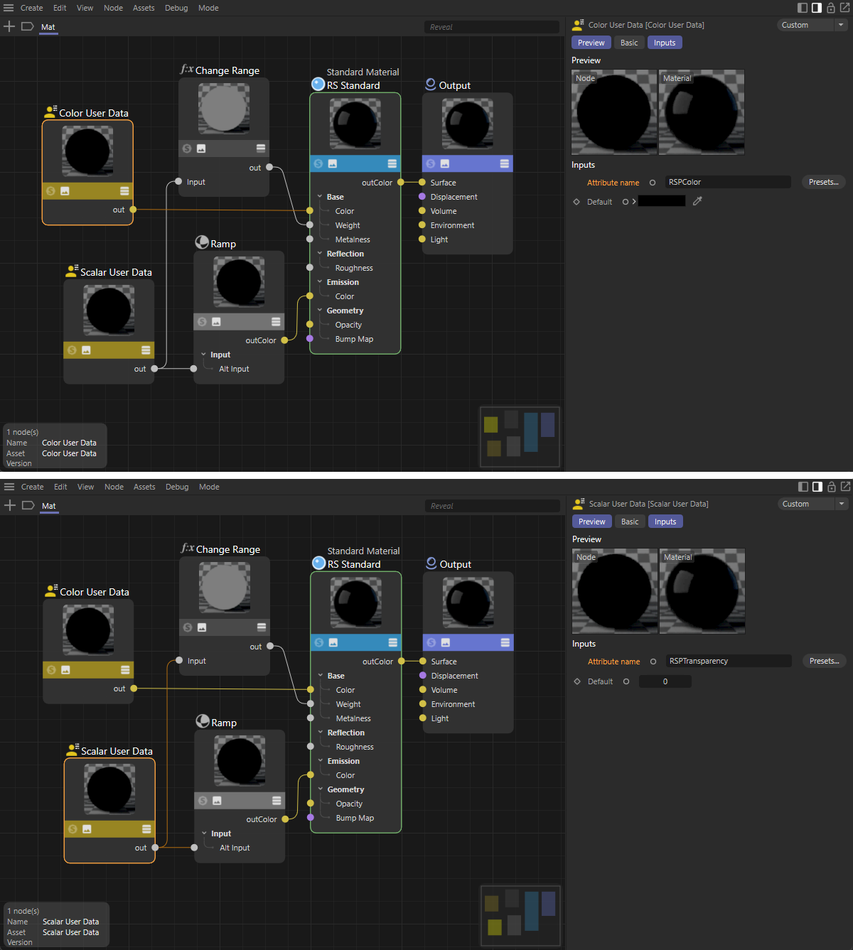 The top shows the configuration of the Color User Data node, with which the color values of the particles are read out as colors for the material. The lower half of the image focuses on the Scalar User Data node, with which the alpha values of the particle colors are read out here. The circuit shows two possible uses of these alpha values in controlling the color influence and the emission colors.
Once you have configured the material as required, it still needs to be assigned in the Object Manager. If you assign the particle shapes via a Redshift Object Tag and use one of the built-in shapes there, you must assign the material directly to the Particle Group. Only if you use custom objects will the material instead belong to the corresponding object that you have defined as a Custom Object in the Redshift Object Tag.
This also applies if you use a MoGraph Cloner object in Object Mode to clone other objects to the Particle Group. The material can then be assigned directly to the Cloner object. However, to transfer the particle colors to the cloned objects, MoGraph/Color must be used in the Color User Data Node Presets... to obtain the color value. It is currently not possible to use the alpha value of the particle colors in combination with a Cloner object.
|
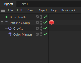
You have already seen how particles are created and managed in a group. The particles in a group can be influenced by forces and modifiers. Forces are already known from the old particle system, for example, and can be found in the Simulate menu under Forces. There you will find common forces, such as Gravity or Wind, to simulate gravity and air movements. Select the desired force object there and arrange it under the Particle Group. The particles in this group are thereby influenced by these forces. Here you will find all these force objects described in detail. The special Modifier objects, which you can find under Simulate/Modifier, work in a similar way. These are also usually grouped under the group whose particles they are supposed to influence (see adjacent figure). |
The Color Mapper modifier can be used to assign color and alpha gradients. To do this, first select the Source to be used for assigning the colors using this modifier:
The example shown below uses the Age Percentage property, which refers to the Lifetime of the particles indicated on the Emitter. The Lifetime of the particles is set to infinite by default (Lifetime = 0) and should therefore be limited manually at the Emitter in order to be able to implement coloring based on the Lifetime.
A particle that has just been created will then have an Age Percentage of 0%. This value increases linearly to 100% until it reaches the end of its life. In this example, we also define the Lower and Upper values accordingly. A read-out Lower value leads to a color removal at the left edge of the color gradient. Particles with an Age Percentage value of Upper lead to a color removal at the right edge of the gradient. This principle also works accordingly when using other particle properties, such as Velocity Speed or particle Radius.
You can edit the colors within the gradient by clicking on the small arrow to the left of the gradient to make its color tab settings visible. A clicked color tab on the gradient then makes its exact position and its color value available for editing below the gradient. New color tabs are created automatically by clicking on the gradient. Color tabs that are not required can simply be dragged up or down out of the gradient with the mouse.
Once the desired colors have been configured, you can also configure their alpha values. To do this, activate the Edit Alpha option below the gradient. This hides the color gradient and replaces it with a grayscale gradient. You can set as many of your own color tabs as you like and adjust their brightness values. White stands for completely visible colors and black for complete transparency. If you want to view the effect of your alpha values on the color gradient, also activate the Display Result option.
If you now place this Color Mapper modifier under the Particle Group and let the animation run, you can observe the color change of the particles (see figure below). The alpha values are not taken into account in the display in the viewport. However, as explained in the section on using materials for particle rendering, this alpha information can also be read out via a Scalar User Data node and used to control various material properties.
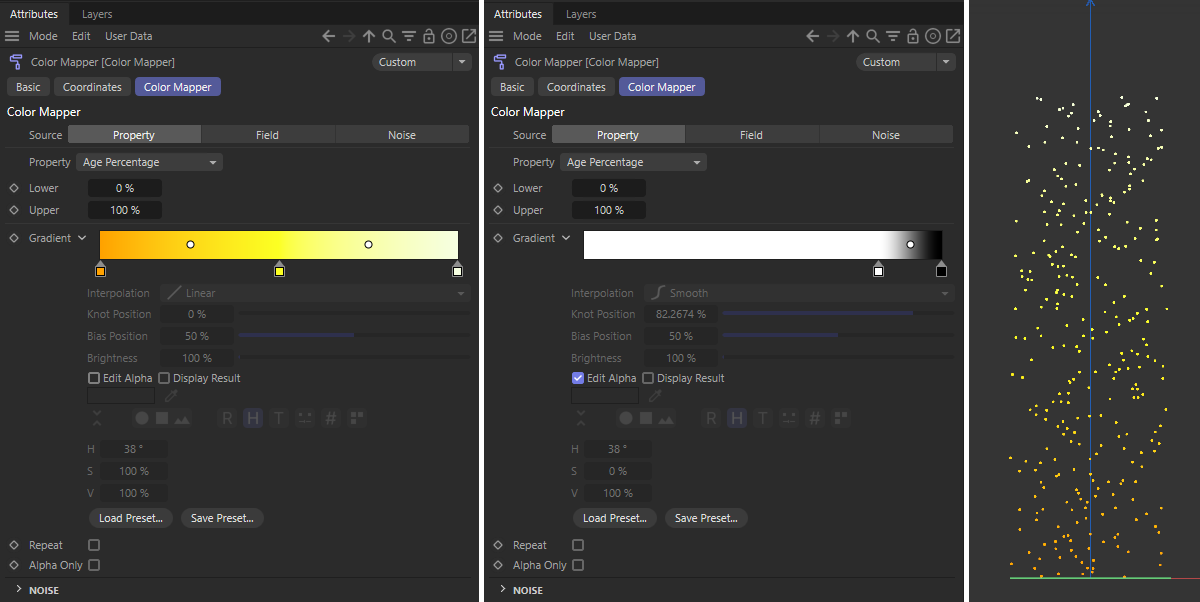 Here a Color Mapper modifier is set so that the Age Percentage of the particles is used to read out a color gradient. Depending on the state of the Edit Alpha option, the colors and the alpha values can be configured separately. On the far right you can see a possible result in which the particles change color according to their Age Percentage.
Similar to the Color Mapper, a Data Mapper can be used to evaluate particle properties, Field objects or Noise in order to influence individual properties of the particles. Below you will find some examples.
We first use a Data Mapper to link the distance traveled by the particles with the red component of their color. While the Color Mapper can only control the complete color and its alpha value, the Data Mapper can be used to control each individual color and alpha component. So to control a complete color value (red, green and blue), three Data Mappers would have to be used.
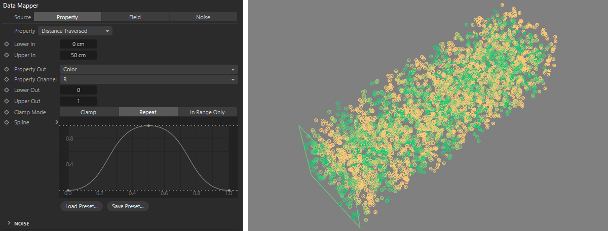 The distance covered by the particles is recorded here and evaluated relative to the Lower In input and Upper In input specifications. A component of a vector or a color, for example, can be changed via the Property Out setting and its Property Channel specification. Here, the red component of the particle colors is increased to 1 and reduced again to 0 every 50 distance units covered. This cyclical repetition is triggered by the Repeat option for the Clamp Mode.
As demonstrated above for individual colour values, the individual components, e.g. the velocity vectors, can also be changed. In the following example, a spherical field is used to change the X-velocity component between 0 and 100. The Lower Out value is applied to the outer edge of the field and the Upper Out value is used in the inner area of the field. As a result, the initially cuboidal particle flow is shifted to one side along the positive X-axis.
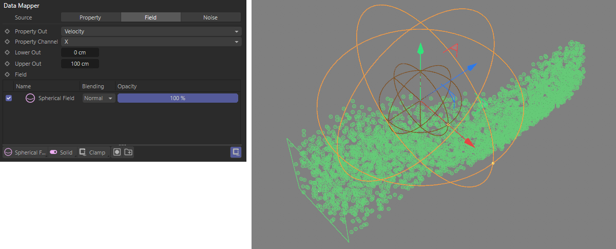 Here, a spherical field is used to increase the X-component of the particle velocities up to 100. In the outer area of the field, this component is reduced to 0 again. Therefore, the particle flow remains constant in its direction after leaving the field.
The same principle can be used to control the Radius size, for example. In the following example, a spherical field is used again. The particles are given a Radius of 2 cm on the outside of the field and a Radius of 0.1 cm in the center. If you activate the option for Draw Radius in the Particle Group, the Radius change can be viewed directly in the viewports without rendering.
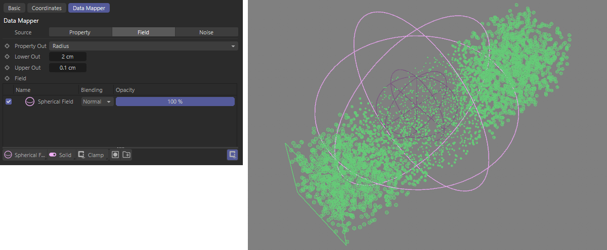 Here, the Radius of the particles within a Spherical Field is changed between 2 cm and 0.1 cm.
In addition to influencing colors and particle properties, particles can also be combined with physical simulations. For example, you will find a Collide modifier that can be used to evaluate distances between particles and another geometry. Particles can then be provided with the typical settings for Bounce or Friction, for example. To do this, Collider Tags must be assigned to the corresponding objects that are to interact with the particles. You can find these tags in the Object Manager under Tags/Simulation Tags/Collider.
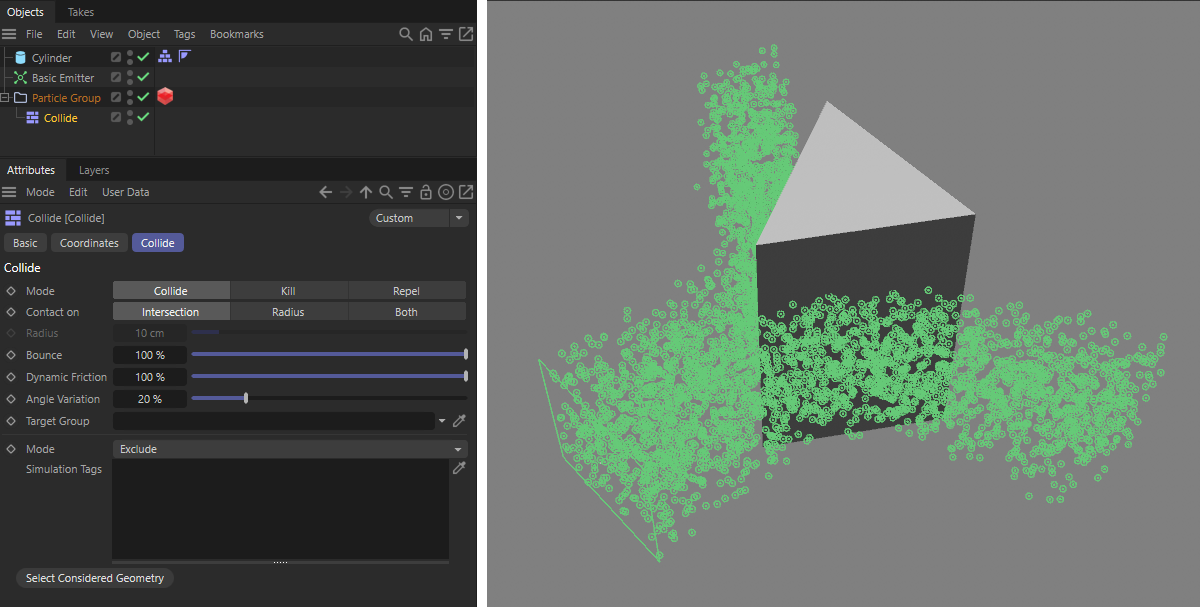 Thanks to the Collide Modifier, particles can bounce off objects that have a Collider Tag.
As you can see in the left part of the figure above, the Collide modifier also offers the option to specify a Target Group. This automatically assigns the colliding particles to a different group, which makes it easier to assign modifiers that only affect the bounced particles, for example. You can simply call up a new particle group from the Simulate menu and then assign it to the Target Group field using drag & drop, for example, or click on the Pipette icon behind the Target Group field and then click on the new Particle Group in the Object Manager.
However, it is also possible for particles to react to their neighboring particles, for example to simulate flocking or predator/prey behavior. These include the Flock Modifier, which can be used to calculate the forces of attraction and repulsion between neighboring particles.
In the following example, we use two Emitters that manage particles in two separate groups. The left-hand emitter produces white particles with a Radius of 5 cm, the right-hand emitter produces violet particles with a Radius of 1 cm. Both Particle Groups are combined in a Multi Group. To do this, simply drag the two Particle Groups into the Group Links list of the Multi Group. If you now assign modifiers under the Multi Group, they will automatically affect all the Particle Groups listed in it. We now drag a Flock Modifier under the Multi Group and adjust its settings and different radii to define the desired attractions and repulsions between these particles. In this example, this leads to an attraction between all particles, which results in a merging of the particle flows. The color and radius differences between the two original Particle Groups would normally be retained.
However, if we now add Blend Modifiers under the Multi Group, we can also mix the different colors and radii with each other depending on the particle distances, thereby further homogenizing and equalizing the appearance of the resulting particle stream. Since only one property of the particles can be mixed per Blend Modifier, we use two of them, one for the colors and one for the radii.
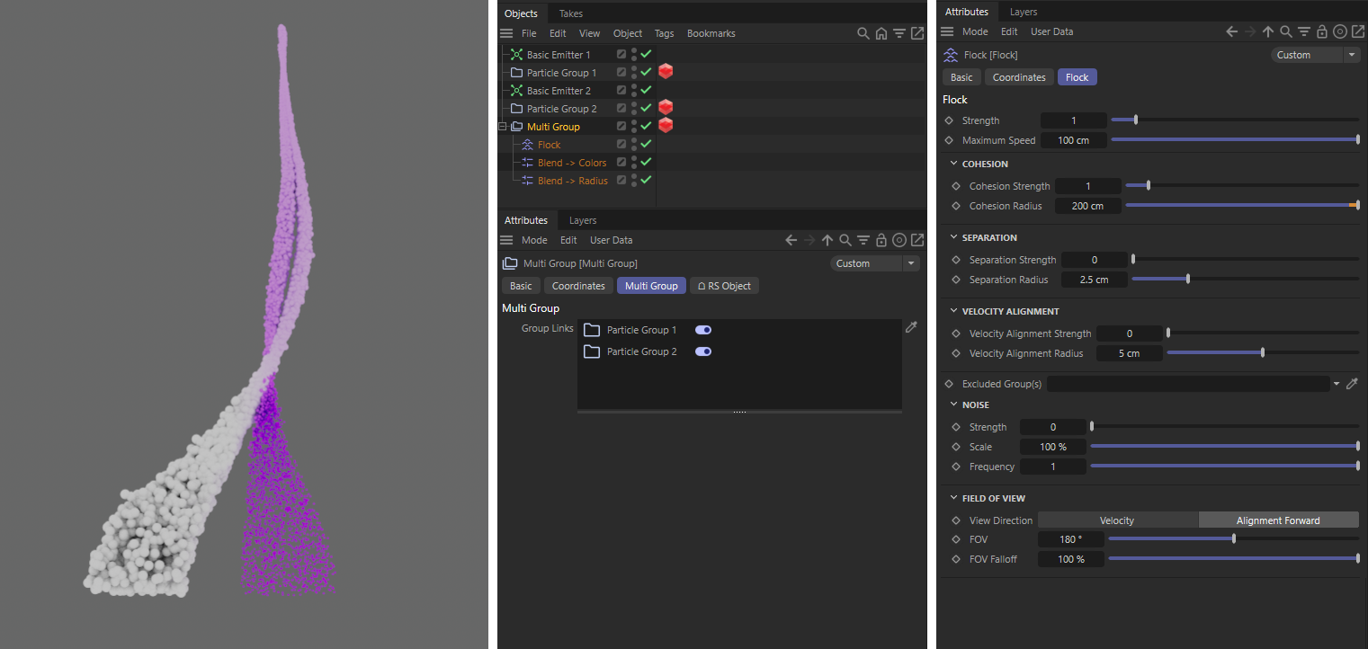 The neighboring particle streams of two Emitters can be merged with a Flock Modifier.
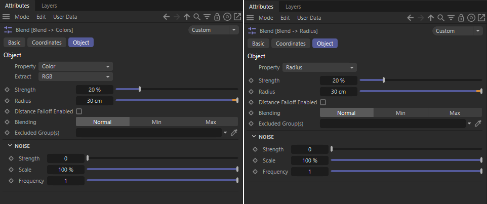 Blend Modifiers can be used to balance the properties of neighboring particles. Here, the Color values (left) and the Radii (right) are evaluated at a Radius of 30 cm around the position of each particle and mixed and balanced according to the Strength specification (Blending Normal).
The combination with the Pyro simulation of smoke or fire is certainly also obvious. A modifier is also available for this, which ensures that the particles are automatically moved by the density and temperature movement of the Pyro simulation. The best way to do this is to first save the pyro simulation in a cache file using the Pyro Output object. Don't forget to at least activate the options for Density, Temperature and Velocity for caching. Then place your Particle Emitter so that new particles are created in the area of affect of the Pyro simulation. These particles do not necessarily have to have their own speed. Think of the sparks in a campfire, for example. The particles could then represent these sparks by forming near the embers and being moved along by the rising heat and density.
All you need to do is assign a Pyro Advect Modifier to the Particle Group and select how strongly and to which Pyro components it should react. If you have not worked with Pyro simulations before, you will find a comprehensive introduction to the topic here.
You have now become familiar with the Emitters, the Particle Groups and also the Force objects and Modifiers with which particles can be created, managed and controlled. The groups are particularly useful for carrying out different modifications on the same particle stream. For example, we can divide the particles of an Emitter into different groups and color them differently or, for example, assign different properties to them. We have already mentioned the Collide Modifier, which can automatically move colliding particles to a new group. The Condition objects are specially designed for this function, i.e., for changing particles to a new group, but also for filtering particles within a group. The properties of the particles can be specifically read out there and then the criteria for a group change or the application of modifiers can be defined, for example, using logical comparisons. Let's take a look at examples of this too.
We start by calling a Circle spline in the XY plane and a Spline Emitter. The Spline Emitter uses the Circle to create new particles in its vicinity, which we assign a Lifetime of 200 frames and a yellow Color at the emitter. In addition, we call a Rotation force object and assign it to the Particle Group that was created together with the Spline Emitter. This moves all particles on circular paths like in a tornado or a whirlpool. Use the Angle Speed on the Rotation object to set the desired speed of rotation.
In the next step, we add a Condition under the Particle Group. This works like a Compare node in the scene nodes or in XPresso or like an if query in programming. We can therefore query a property of the particles and then compare it with our own values. If the check is positive, the corresponding particles can be specifically influenced by forces or modifiers that are grouped under the Condition.
In our example, we use the Alignment Property to select the rotational position of the particles in space as the value to be read out and use Extract Forward Dot Product to define that we are interested in the Z-axis direction of the particles. The alignment of the particles is initially ascertained directly by the Emitter and can also be updated during the particle flight, e.g., using the Look Modifier.
The lower part of the Condition settings then deals with our own specifications that need to be fulfilled. With Comparison Inside Range, we can define an angular range in which the Z-axis of the particles must move. The axis system of the Condition object is used as the reference system. In our example, the angles between the Z-axes of the particles and the Z-axis of the Condition object are calculated and then compared with the angular range between the Lower and Upper. If required, you can use the Chance value to define how strict this check should be.
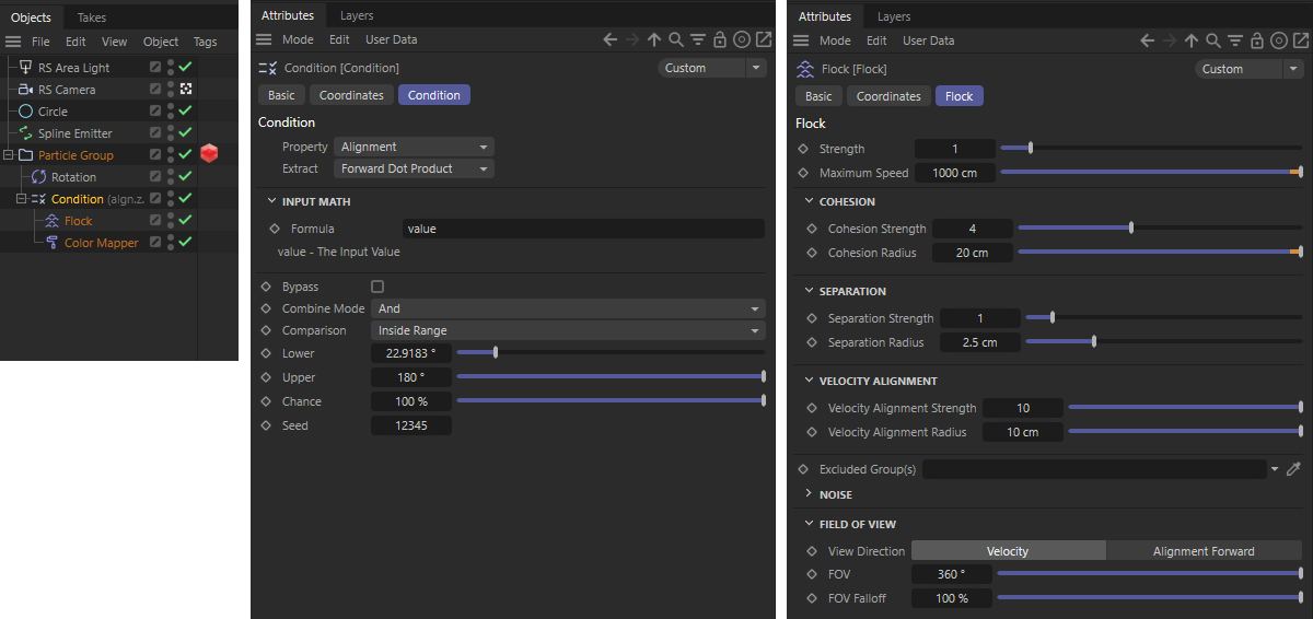 The conditions here compare the orientation of the particles with the axes of the Condition object. If the angle determined is within the specified angle range, modifiers grouped under the Condition object can have a targeted effect on these particles. In this example, these particles are specifically recolored and provided with a Flock modifier with attractive forces.
As you can see in the figure above, we then add a Flock and a Color Mapper modifier, which are grouped directly under the Condition. This means that these modifiers only affect the particles whose alignment meets the condition. The Flock modifier ensures interaction between the particles and the Color Mapper ensures uniform coloring. This is generally helpful to be able to see directly whether the right particles are being sorted out. The following animation shows a possible result.
In the next step, we add a second Condition, which this time queries the Age Percentage of the particles and - if this is over 25% of the Lifetime specified by the emitter - automatically deletes the corresponding particle. For this to work, a limited Lifetime of e.g. 200 frames must be specified in the emitter. By default, particles are generated without a Lifetime limit, which would generally make the use of Age Percentage impossible.
We place this new Condition under the first one and thus obtain an additional check of the particles. You can therefore use the Combination Mode setting to select how these multiple checks are to be combined. The default setting And ensures that both the first Condition and the second Condition must be positive in order to activate the modifiers placed under the second Condition. A Kill modifier is used there, which removes the particles.
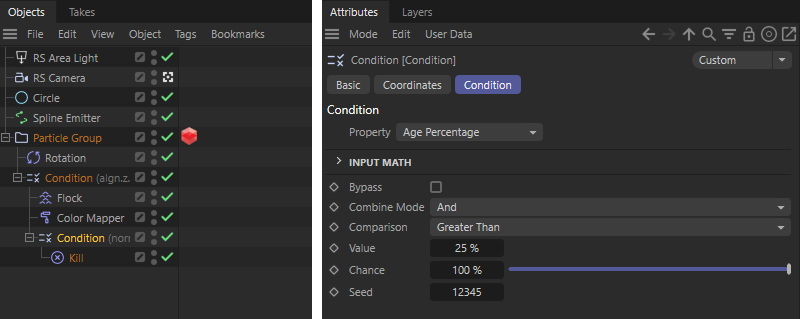 The second Condition supplements a second check regarding the percentage Lifetime and leads to the premature end of life of the particles.
The above example has shown how Conditions can be used to limit Forces and Modifiers to a specific part of the particles. An even stricter separation of particles can be achieved by a group change, which is also preceded by a Condition query. In the following example, we use a simple Basic Emitter as a basis with which particles are emitted in the Z direction and assign a gravitational force to its Particle Group (Simulate/Forces/Gravity). The particles then fall down when the animation is played. Now a Condition should ensure that the particles rise again after a certain period of time. This time we will select a Time Condition with which time intervals can be recorded and group them under the Particle Group. At the Condition, we switch to Pulse mode and set the Start Frame, Duration and Gap to 10 frames each. This will output all the particles under the Condition that appear from Figure 10 onwards for the following 10 simulation frames. The defined Gap was then provided for a period of 10 frames in which the Condition has no function. The cycle of 10 frames is then repeated.
Under this Condition, we sort in an additional gravitational force, this time using an acceleration that is twice as large but negative (see also the following figure). This results in the first gravitational force (with the default value of 981 cm) not only being compensated, but the resulting gravity acting with the same strength in the opposite direction.
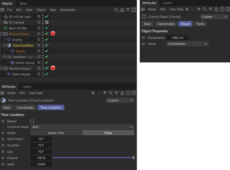 The Time Condition subjects the particles to a cyclic time interval with a negative acting gravity.
To end the effect of gravity on the particles, we add a normal Condition that queries the Age of the particles. Particles that are older than 20 frames should be sorted out and moved to a new group. To do this, we use the Switch Group modifier under the new Condition. We also call up a new Particle Group and assign it to the Switch Group modifier. The older particles are then directed to the new group (see figure below).
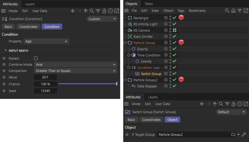 We use a second Condition and a Switch Group Modifier to move particles to a new group.
The sorted out particles in the new group are no longer subject to gravity, but can still retain the last direction of movement and therefore drift apart upwards or downwards. We therefore create a Data Mapper modifier under the new group and have the Y component of the velocity read out there and set to zero with the subsequent Output property settings. We simply leave the entire input range with Lower In and Upper In at 0. By using Clamp Clamp Mode and a linear curve in the Spline graph, our value 0 is output in any case, which we use for Lower Out and Upper Out.
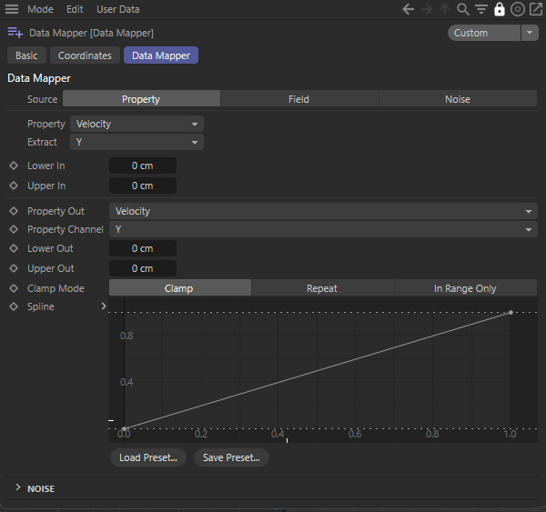 With these settings, all Y components of the speed vectors are set to zero.
The video shows a possible result of the simulation described above.
So far, we have always sorted the Forces and Modifiers directly under a Particle Group. This allows us to compress even complex particle controls in the Object Manager by collapsing the groups. However, Conditions and Modifiers actually affect everything that is available at their hierarchy level. The following example shows how you can make use of this.
Here you can see a single Basic Emitter whose particles randomly change the Y and Z direction in a fixed rhythm. Let's take a step-by-step look at the implementation.
First, create a Basic Emitter with a rectangular surface and compress it strongly along the X direction so that the particles only emerge in a narrow gap. Activating the Shot emission only generates the specified particle Count once from the specified Start Frame. We are initially trying a low value of 20 here. In the Properties of the emitter, we specify a custom Velocity Direction with the vector 0, 1, 1. This causes the particles to start at an angle of 45° along the positive Y and Z axes. The following figure shows these settings.
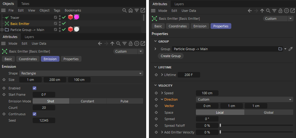 The settings of the Basic Emitter
Now we add two Time Conditions under the Particle Group. These are able to activate subordinate Modifiers at any time interval. We use the Pulse Mode for both, each with a Duration of 1 frame and a Gap of 10 frames. The difference lies only in the Chance value. This corresponds to a random variation of the results. The first Time Condition uses a Chance of 50%. This means that every 10 frames there is a 50% chance of activating the subordinate Modifiers.
The Time Condition in second place below the group uses a Chance of 100% and therefore receives all particles that have not already been processed by the first Condition. Under both Conditions, we use Switch Group Modifiers in which we link a newly-created Particle Group. With this setup, we randomly divide all 10 animation frames into two groups.
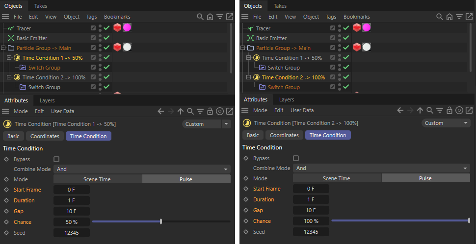 The settings of the two Time Conditions
As the following image also shows, Math Modifiers are used in both new groups. These multiply the Y and Z components of the speeds by -1 in each case and thus lead to a reversal of the direction of movement in the corresponding direction.
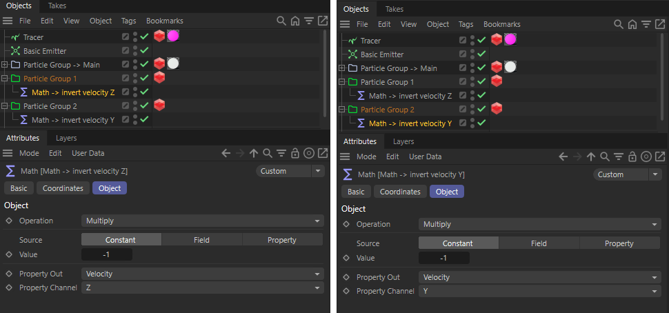 In the two new Particle Groups, Math Modifiers ensure that the direction of flight is reversed. The first group inverts the Z component and the second group the Y component of the speeds.
The trick now is to copy the particles back into the main group so that the Time Conditions are recalculated and a random variation of the flight directions occurs again in the next time cycle. This is done by a new Switch Group Modifier, which is placed at the end of the hierarchy (see left half of the following image). Since all Modifiers and Conditions are processed from top to bottom and Modifiers and Forces that are not in any hierarchy can access all particles, the particles of both groups are transferred back to the main Particle Group.
The right half of the image also shows the use of a MoGraph Tracer, with which the trajectories of the particles can also be traced as a spline. To do this, simply drag the main group of the particles into the Trace Link field. Via the From End Limit setting in conjunction with the Amount value. the traced paths are automatically shortened according to the specified number of frames.
If you also add a Redshift Object Tag to the Tracer, the Trace Paths can also be rendered directly without creating real geometry. You will find a Curve category on the Object Tag.
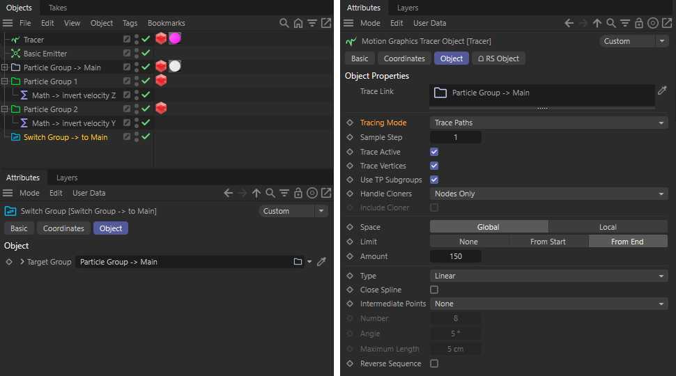 Changing the group at the end ensures that all particles are moved back into the main group so that the cycle can be repeated. An additional Tracer traces the trajectories of the particles.
As an additional effect, you can now, for example, add the option of automatically reducing the speeds in the outer area, which can create even more detailed shapes. We implement this via additional Conditions and Data Mapper Modifiers, which are directly subordinated to the main group (see the following images).
The first Condition checks whether the Y component of the particle velocities is greater than 0, i.e., positive. In this case, a subordinate Data Mapper is executed that uses a Field object as the Source. For example, we use a Spherical Field here. We select the Y component of the speed for the output and set values between 10 and 100 (see right-hand side of the following image). This assigns new values between 10 and 100 to all positive Y velocity components, which result from the affect radii of the Spherical Field. The value 100 is output in the core area of the Spherical Field and the value 10 in the edge area.
Now we have to take care of the particles that use a negative velocity along the Y-axis, i.e., fly diagonally downwards.
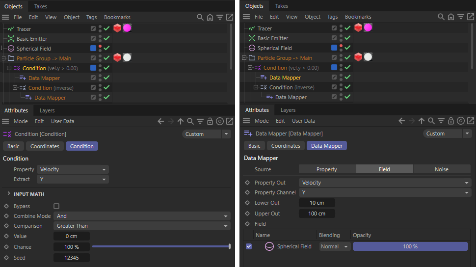 Scaling of the positive Y-velocity components over a Spherical Field.
We add a second Condition grouped under the first Condition, which uses the Inverse Combine Mode and thus receives all particles that were not processed by the upper Condition. In our case, these are all particles that have a negative Y-component for the velocity. A new Data Mapper under this Condition accesses the same Spherical Field and also writes new Y-velocity values back to the particles, only this time negative values (see following image).
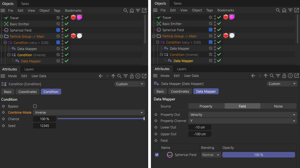 Scaling of the negative velocities along the Y-axis via a Spherical Field.
Then repeat this part of the circuit, only this time for the Z components of the velocities. You can also link the same Spherical Field again. In this way, you only have one Spherical Field object that you can use to control the entire decrease in velocity calculations.
 A possible result of the above particle circuit
To conclude this topic, the following section shows how you can isolate related particle systems in Simulation Scene objects despite this scene-wide use of Forces or Modifiers.
The particle simulation is also subject to a simulation environment, which is defined by default via the Scene Settings. You will find these when you call up the Scene Settings in the Edit menu. You will then find a Simulation tab in the Attribute Manager, where you can also find the settings for the particle simulation.
You can use isolated Scene Settings for your simulations if you use Simulation Scene objects and group your simulations under the respective components. Let's take a look at a simple example with regard to particle simulation.
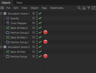
Let's assume you want to use three Emitters in the scene, two of which should be affected by the same effects and Forces. You could now work with a Multi-Group for the two Particle Groups of the Emitters and assign the corresponding forces and Modifiers there. However, an alternative to this is to classify the two Emitters and their groups under a new Simulation Scene object. You can also sort a Gravity force and a Color Mapper Modifier directly there, for example. Both particle systems are automatically affected.
The remaining, third particle system with its Emitter and Particle Group is assigned to a second Simulation Scene. This completes the separation.
The separation of the simulations even goes so far as to affect the caching. Even if you start caching for the entire scene at one of the Particle Groups in the first Simulation Scene, only the simulations within the Simulation Scene are taken into account.
For a particularly individual effect, the particles can also be given automatically or manually generated values. These values can be written and read directly via various modifiers. Here is another example:
Some properties can already be found directly on the emitters on a special Output page of the settings. For a Basic Emitter, for example, the Born option can be activated there, which automatically creates a property with the name born. The value of this variable is automatically set to false and only changes to true during the simulation phase if the particle has just been generated at the emitter. As each particle is individually marked with true or false, the born property can be used at any time during the simulation to query whether it is a newly created particle or a particle that has already existed for some time.
This is an example of an Automatic Custom Property, which is then also listed under this term in the Scene Settings for particles. Similar options for automatically generated properties can also be found on some modifiers, such as Flock, Blend or Collide.
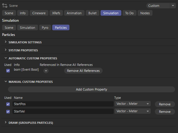
In the lower half of the figure above, you can also see that there is also a section for Manual Custom Properties. You can also create your own properties there using the Add Custom Property button and give them the desired name and data type. We create two additional properties there for this example, each of which uses the Vector - Meter data type and is therefore suitable for passing on positions or speeds, for example. We name these properties accordingly with the terms StartPos and StartVel. You can actually use any names here that you want to use to fill these properties with values or read them out within the simulation. You can find more information on creating custom properties on these pages of the documentation, among others.
Many of the common Conditions and Modifiers now make it possible to evaluate or write values for such properties, for example to specifically change the behavior of particles or to change everyday properties such as radius, speed or color. In our example, for example, we use the state of the born property via a Particle Condition and only execute the Node Modifier for a particle if it has just been created on the emitter.
The left side of the following figure shows the evaluation of the born property for a Particle Condition. The Particle Node Modifier grouped below the condition is then only executed for the newly created particles and contains two Set Custom Particle Property nodes, which fill our self-created StartPos and StartVel properties with the current position and velocity of the particles. All you have to do is enter the names of our properties and their Vector Data Types at the nodes and connect their Property Value inputs to the Position and Velocity inputs in the Particle Nodes Modifier.

We can use this stored information about the individual starting position and starting velocity of all particles, for example, to reset particles to this initial state at the emitter after an arbitrary period of time. The particles then behave exactly as if they had just been created and can then set off on their journey again. Identical starting positions and starting velocities, which are made up of the direction of flight and the velocity speed, generally result in identical trajectories for the particles. In this way, seamlessly repeatable (looping) particle simulations can be generated, for example. The following video and the scene linked next to it demonstrate this effect.
This is made possible by two additional Conditions within the Particle Group, in which the Age of the particles is queried in each case. Here we arbitrarily set an Age of the particles of around 49 frames, at which point the particles are to be reset to their original state. Since the Age also works with fractions of frames and particles can also get born between the animation frames of the simulation, the trick with the two nested Conditions is helpful in order to be able to filter out a certain range of particle Ages. To do this, we configure the upper Condition with the Comparison Greater Than and the Value 48 F and the subsequent Condition with the Comparison Less than and the Value 50 F. This means that under the second Condition we automatically only receive the particles that are on average 49 frames old.

Now we just need to write the stored start positions and start velocities back to these filtered out particles. Math modifiers, for example, can be used for this, as these can also be used to assign read property values to certain particle properties. Since vector properties can only be assigned individually for the X, Y and Z components, we use three Math modifiers and configure them as shown in the following figure. For example, the X component of the Position Target Property is replaced by the X component of our custom StartPos property. It should also be noted that the Multiplier should be set to 1. Otherwise, the value of a custom property could still be scaled.
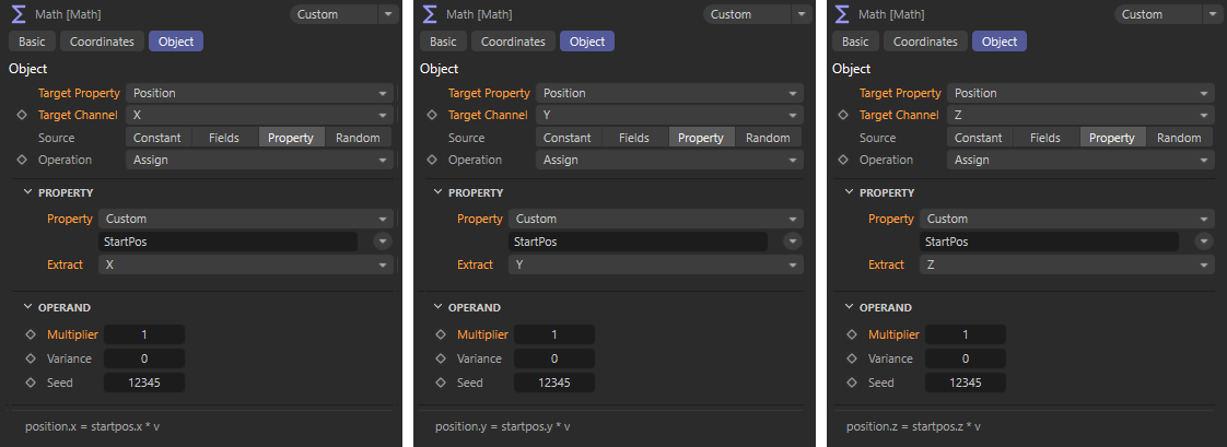
We repeat this assignment using three more Math modifiers, only this time we use the Velocity direction under Target Property and the name StartVel for the Custom Property.
As mentioned above, the velocity of a particle is a combination of the direction of flight and the velocity speed. The velocity vector therefore indicates the direction of flight by its direction and the speed at which a particle is traveling by its length. The assignment of the Velocity therefore does not yet contain the velocity speed of the particles. We now make up for this assignment with a final Math modifier.
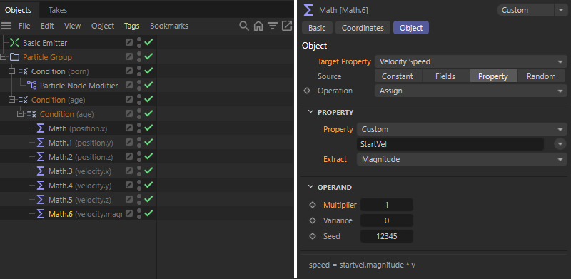
As can be seen in the figure above, the Length of our velocity vector stored in StartVel can also be Extracted and transferred to the Target Property Velocity Speed. If the option for Range is then activated on the Basic Emitter, the time period after which the emission should end automatically can be defined via the Duration value (see following figure). If we use 49 F there for the Duration, the emission of new particles ends exactly at the moment when the older particles are moved back to their original position on the emitter.
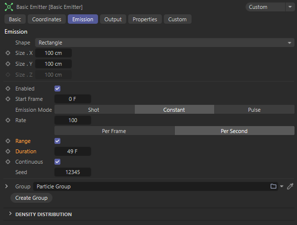
In order to render a loopable video of this simulation, we select the point in time at which the Emitter stops working as the first frame to be rendered. This would therefore be frame 49. The last frame to be calculated is therefore 49 plus the looped particle age (49 frames) minus 1 image, i.e. frame 97.