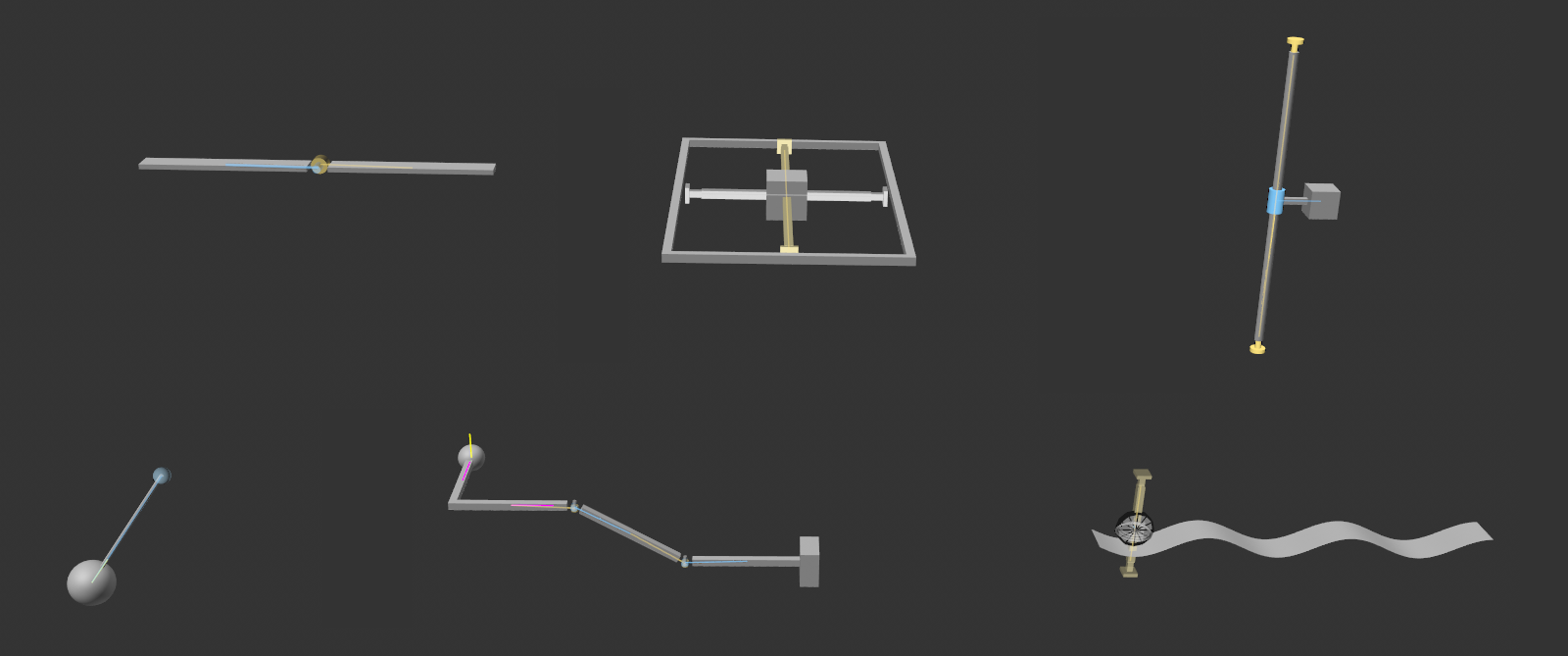
Connector
![]()
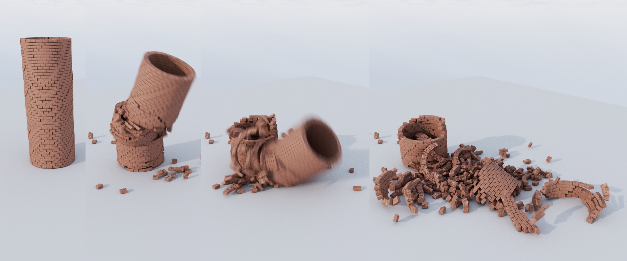 Breaking Connectors of the "solid" Type ensure that not everything falls apart, but only Connectors under the greatest stress: Very practical for debris parts that are still connected.
What are Connectors?
Connectors restrict the movements/rotations of Rigid Bodies and Soft Bodies (the latter only when using Bullet).
Connectors connect objects of the following type:
- Rigid Bodies.
- Soft Bodies (only in conjunction with Bullet Dynamics).
The Connectors therefore work together with both:
- The old Bullet Dynamics system, whereby the Connectors of old scenes are converted into the new ones.
- The new Simulate system.
Without Connectors, Rigid/Soft Bodies would only react to forces and collisions. For example, it would be very time-consuming to create a simple door hinge. With a Connector (Angular Type, Hinge mode ), however, this is possible without any problems.
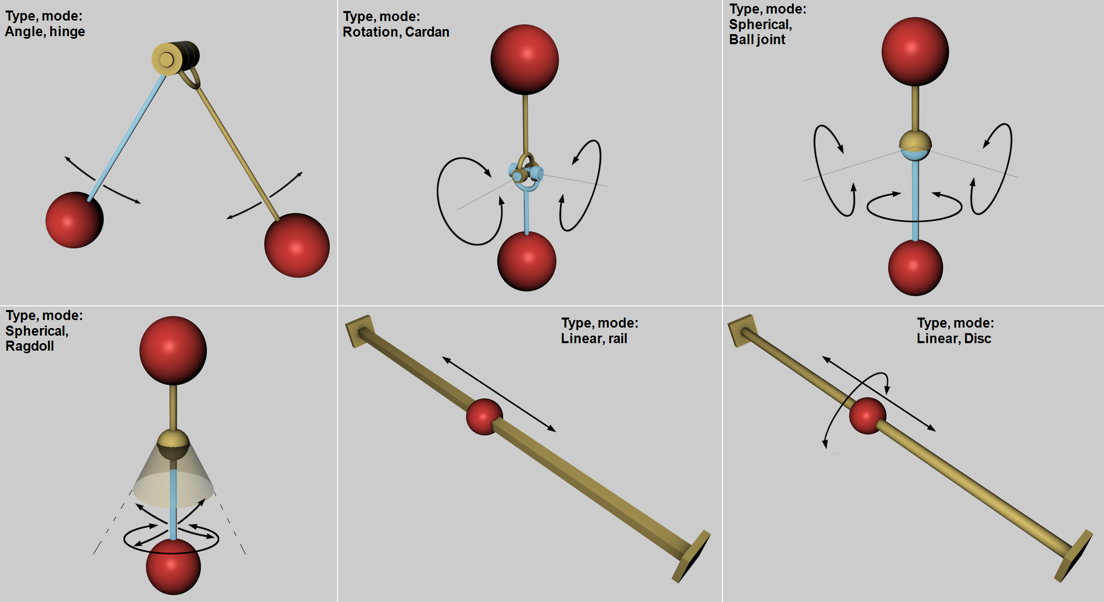 Some Connector types The arrows indicate the possible directions of movement and rotation. The Area, Box and Wheel Suspension modes not shown are basically combinations of the above.
Connectors of the Fixed Type are of particular importance. These do not allow any relative movements, but simply "only" hold Rigid Bodies together. The trick here is that if definable forces are exceeded, these can break, causing the object to break as well (see also above).
Connectors are displayed in the Viewport with a functional preview so that the restrictions can also be understood visually at a glance.
Non-functioning Connectors will be displayed in red when the simulation starts. This can happen, for example, if both linked partners are not Rigid Bodies.
Creating Connectors interactively
Connectors can already be created with objects without a Rigid Body tag. However, they only work correctly if Rigid Body tags have been assigned.
-
Select the objects to be linked in the Object Manager.
-
Call up one of the Connectors in the main menu under .
-
Slide or rotate the Connector in the Viewport to the correct position (where there is a hinge or parallel to the axis of a slider).
Please note that Connector objects themselves cannot be cloned. Cloning complete setups (e.g., a vehicle as in the example below to create autonomous vehicles) is not possible with the Simulate system - but it is possible with Bullet Dynamics.
The Connector object as a container for other Connectors
The Connector object is then a kind of container for many individual connectors.
Now, of course, it would be nice to give these many connectors individual properties. For example, this one special Connector should be the first to break. There are two solutions for this:
-
For the most important Connector parameters, there are link fields ( called selection or weighting) in which MoGraph Selection tags or MoGraph weighting maps can be accommodated (see also here), which control the corresponding properties at connector level.
-
The Connector object can be resolved by making it editable (C key). All contained Connectors are then packed as a Connector object under a null object. These only ever contain exactly 2 objects in their object list. You can then use this method to access the settings for each individual Connector.
Connector position
The connector position and orientation are important. These define the axes of movement and rotation. If you look at the image above, for example, the possible directions of rotation of the balls on the hinge are defined by the joint position, just as the position of the Rail Connector defines the direction in which the ball can move.
The hinge is usually positioned on an axis of rotation.
Once the simulation has started, the Connectors will automatically move along with their linking partners in a meaningful way. The Connector object therefore does not have to be placed somewhere hierarchically in order to function.
Consider the following simple scene: 2 cylinders, 2 cubes, each with a Rigid Body tag (you can download the finished scene below):
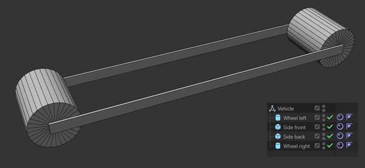
These 4 basic objects should be turned into a functional vehicle.
Without connectors, these 4 components will simply fall down without interacting with each other - apart from possible collisions. To turn the parts into a functional vehicle, you need 4 connectors of the Angle Type, Hinge Mode, which connect the 2 cubes to the rotational axes of the cylinders.
To do this, select the two objects to be connected and create an angle Connector. These objects are thus linked by a Connector.
The trick is that 2 Connectors are located in the first cylinder axis of rotation and the other two Connectors in the second cylinder axis of rotation. It does not matter where the Connectors are located on the axis of rotation. These can be moved axially without disrupting functionality. Of course, it makes more sense to move them to their "real" position, which in this case would be the bearings, i.e.,, where the "interfaces" between rotating objects are located in reality:
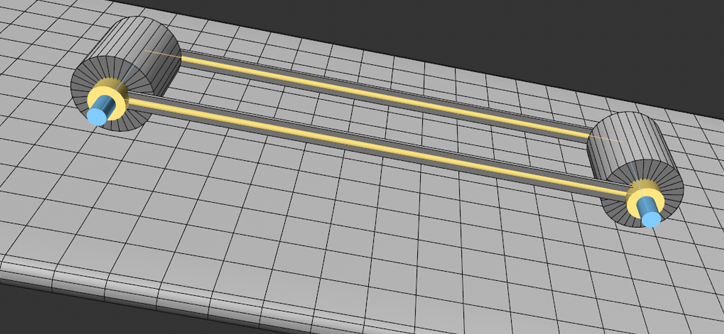
And with this you have actually already created a functional vehicle that can roll independently on an inclined plane. The 4 objects form a fixed group with rotating cylinders.
Automatic positioning
These rules apply when creating new Connector objects or Connectors:
-
If there is only 1 object in the object list, the newly-created Connector will lie at the world origin. The object is thus initially connected to the center of the world - the Connector object can then of course be freely positioned/rotated.
-
If there are 2 objects in the object list, the connector will also be created in the world origin, but will connect both objects - the connector object can then, of course, be freely positioned/rotated.
-
If there are 3 or more objects in the object list - including the clones of Cloner objects - the Connectors will be positioned in the middle of the connected object pairs. If you now rotate/move the Connector object, all the Connectors it contains will bel moved or rotated accordingly.
Imprecise Connectors?
If you have the feeling that the connectors are not doing 100% of their intended job, i.e., they will give way or bounce too much, then it usually helps to focus on the precision of the simulation calculation (primarily represented by the parameters Substeps and Iterations).
Another reason could be extremely large differences in the masses of the objects. Physics simulations generally don't like that very much.
5 Connector commands, but only 1 day?
Even if you can call up 4 different connector types under , it will be only one connector object with different type or mode settings. These can be changed at any time.
Other interesting facts
-
If the simulations of many objects are too similar, the
 Turbulence object can provide a remedy, e.g., by creating a little disorder in a collection of clones.
 -
Do you want to build walls and towers that will collapse? To prevent the spring effect when defining the Rigid Bodies at the start of the simulation, Trigger On Collision can be defined. Higher values for Substeps also prevent overly "elastic" fixed connectors.
-
To illustrate this, you will find some Connector types including Rigid Bodies in motion in the following scene:
