Substance Connector
Direct asset exchange with Adobe Substance 3D Sampler
This functionality enables the direct exchange of Substance 3D assets between the Adobe Substance 3D Sampler and Cinema 4D. All you have to do is open both programs at the same time. No separate installation, e.g. of a plugin, is necessary.
The Substance Plugin for Cinema 4D automatically appears in the Export options of the Adobe Substance 3D Sampler. Individual asset parameters can also be marked directly for transfer to C4D. This therefore also allows you to edit these properties directly in Cinema 4D without having to re-export from the Substance 3D Sampler. We take a closer look at an exemplary interaction between the applications below.
Overview
- Creating a material from a photo in Adobe Substance 3D Sampler
- Working in the Substance 3D Sampler interface
- Edit the material
- Make textures tileable
- Adjusting the physical size of the material
- Modify the material and reveal individual settings
- Export the material to Cinema 4D
Creating a material from a photo in Adobe Substance 3D Sampler
To demonstrate the interaction between the programs, we will go through a typical example step by step, first creating a material from a photograph in Adobe Substance 3D Sampler and then transferring it to Cinema 4D. A simple mobile phone snapshot of a small hard case was created for this purpose, as is used, for example, to transport camera accessories. The surface is protected by a fine-mesh fabric, as shown in the following illustration. You can load the image used in this example as a zipped file by clicking on the following file icon.
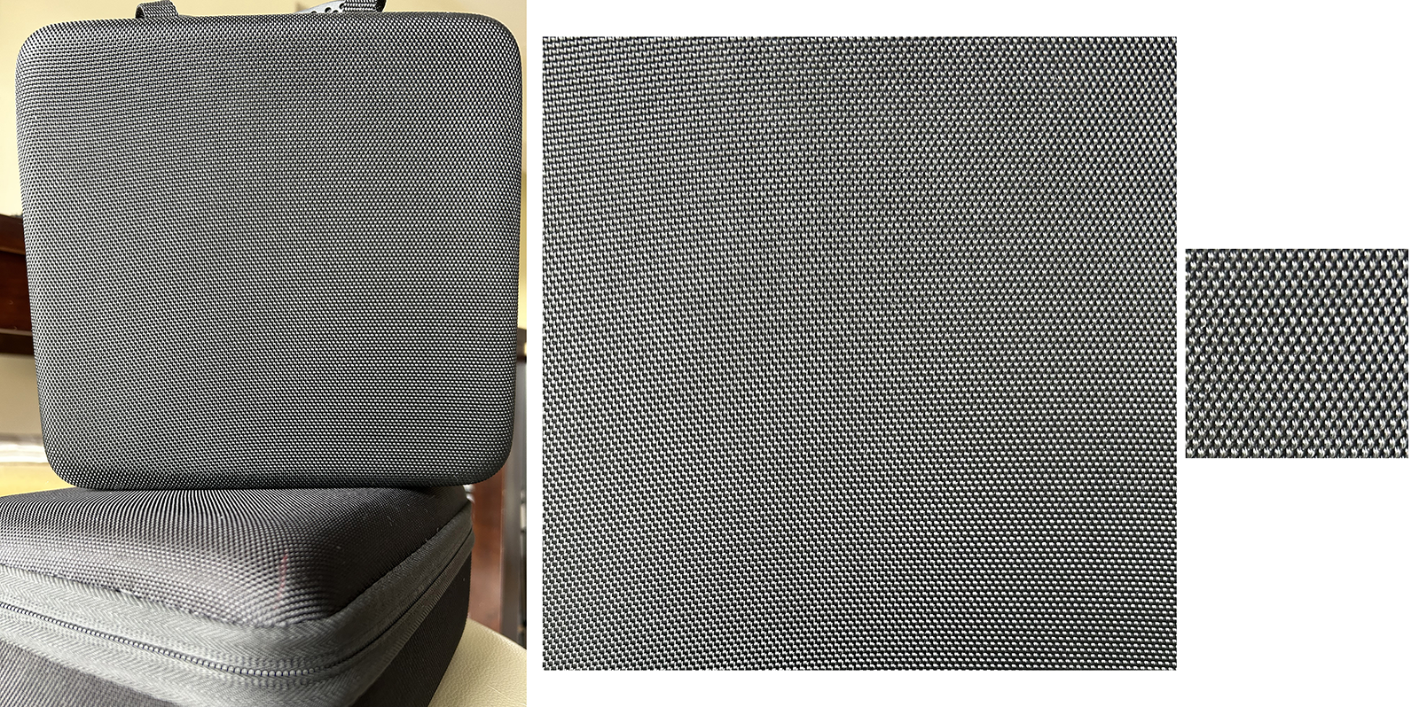 On the left you can see the original cell phone photo of a small hard case, which was transformed with the help of an image editing program such as Adobe Photoshop, a small segment of the tissue structure was cut out (right in the figure).
After opening the Substance 3D Sampler, press the button for New Project. This opens a dialog box in which you will find an area for loading an image directly at the top. Simply drag the corresponding image - in our case the image section of the fabric - into this field or click on the text link for your Computer to use a typical file dialog to select the image file.
Below this area there are various buttons from which you can select the Convert image to material function. The following illustration shows these steps.
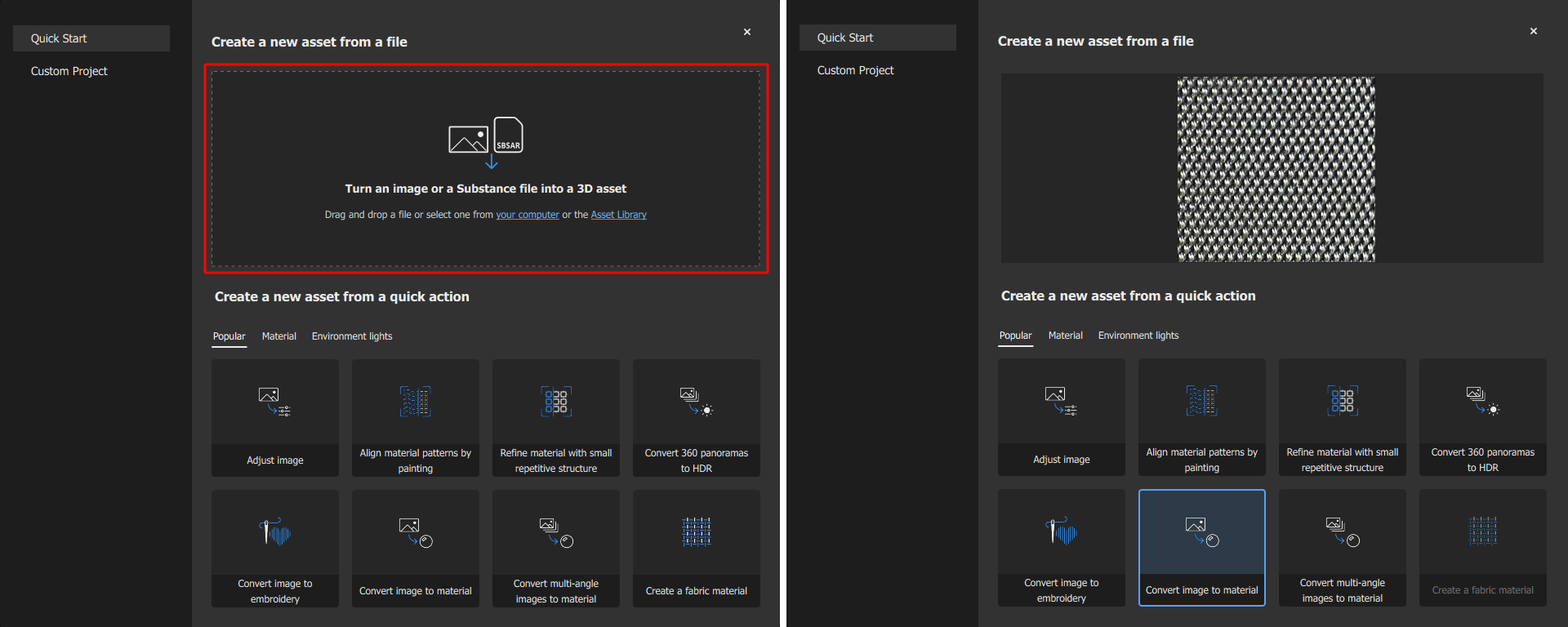 After starting a new project, an area appears into which an image can be dragged (marked with a red border on the left). Below this, there are various buttons that indicate what should happen with the assigned image. In our case, we click on Convert image to material (marked blue on the left).
After clicking the button, you can specify the type of material to be created and its basic gloss behavior. In our case, we select the entry for Fabric (i.e. woven fabric) and Matte as the material type (for rather dull, non-metallic surfaces) for the assigned fabric structure. Both can be corrected later on the material so that no mistakes can be made here. Simply choose what seems plausible to you.
After clicking on the Create button at the bottom right of the dialog window, the main interface of the Substance 3D Sampler is displayed.
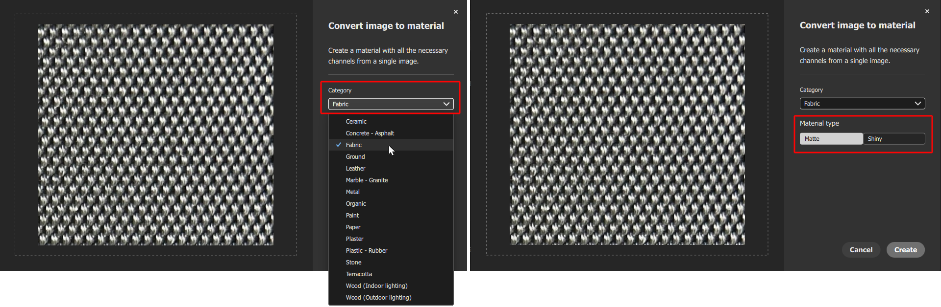 The type and basic gloss behavior of the material can be specified. However, these properties can also be edited at a later date.
Working in the Substance 3D Sampler interface
The material created in the above steps then appears on a geometry in the Substance 3D Sampler's standard interface. Here we briefly outline the most important elements in the interface and their most important functions:
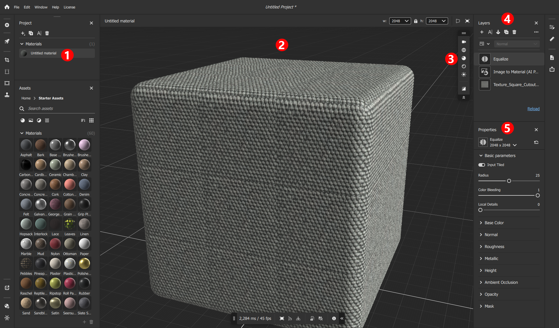 The new material in the Substance 3D Sampler interface and markings for the most important managers and settings.
|
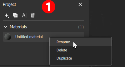
The Project Manager is located at the top left (see number 1 in the full view of the interface above), in which the material that has just been created is listed. Right-click on it to change and assign the desired material name, for example. This makes sense, as this name is then also adopted when transferring to Cinema 4D. |
The main window with a view of a geometry and the material assigned to it is marked under the number 2. Navigation in this window can be controlled by placing the mouse pointer in this view and then performing one of the following actions:
- Mouse movement with the left mouse button held down: The viewing direction is rotated around the center of the view.
- Using the mouse scroll wheel: Zooming the view in and out.
- Mouse movement with the right mouse button held down: Zooming the view in and out, as an alternative to using the scroll wheel.
- Mouse movement with the middle mouse button held down: Moves the viewer position.
|
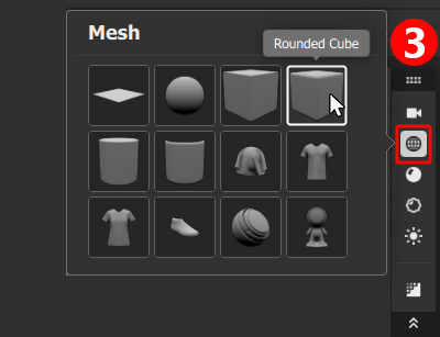
The icons to the right of the view provide access to camera, object or lighting options. For example, clicking on the icon with the wireframe sphere opens a context menu in which alternative shapes can be selected. The material is displayed in the view window for inspection on the shape selected here. Although this shape is irrelevant for the subsequent export of the material, the use of a shape that matches the material makes it easier to assess the property intensities, e.g. for the displacement or the normal map, and also to configure the physical size of the material. |
|
All layers of the active material are stirred in the area marked here with the number 4. These layers can represent complete material descriptions or just typical image processing functions, e.g. for adjusting brightness and contrast. Similar to layer-based image editing programs such as Adobe Photoshop, upper layers can cover or process lower layers. The order of the layers is therefore important and can be rearranged by dragging and dropping with the mouse. |
Edit the material
The creation of the material from a linked image is already accompanied by the use of three layers:
- "Name of image file": The basis of the layer stack is the linked image from which the material is to be created. The name of this file is displayed as the background layer, i.e. the lowest layer.
- Image to Material (AI Powered): This layer calculates all typical properties and textures for the underlying image layer. After clicking on this layer, the initially selected material type or its gloss behavior, for example, can be corrected at any time in the settings window.
- Equalize: This effect, which is added by default, enables the contrast in the material to be adjusted, which is useful as the underlying image is often not created under optimal lighting and therefore the edges of the texture stand out clearly when the material is tiled several times, for example.
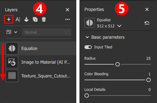
The first editing step should therefore also deal with this Equalize layer. After selecting this layer, four basic parameters become visible in the Properties area:
- Input Tiled: Activate this option if you want the contrast adjustment to be calculated across the edges of the texture tile. The color values from the left-hand texture edge can then also be used to adjust the color values from the right-hand texture edge, for example. This is useful for all materials that are later to cover a surface by repeating them several times.
- Radius: This distance defines the area to be used for adjusting the brightness and contrast.
- Color Bleeding: Intensity with which adjacent color values are mixed together and thus homogenized.
- Local Details: Intensity of preservation of fine details despite the general color and contrast adjustment.
As the material should be tileable, make sure that Input Tiled is active and adjust the setting so that the colors and contrasts no longer show any noticeable repetition patterns. The following illustration compares the original appearance with the adapted material version. If required, this customization can also be overwritten individually for individual material properties. The additional categories such as Base Color, Normal or Roughness in the lower part of the Properties are provided for this purpose.
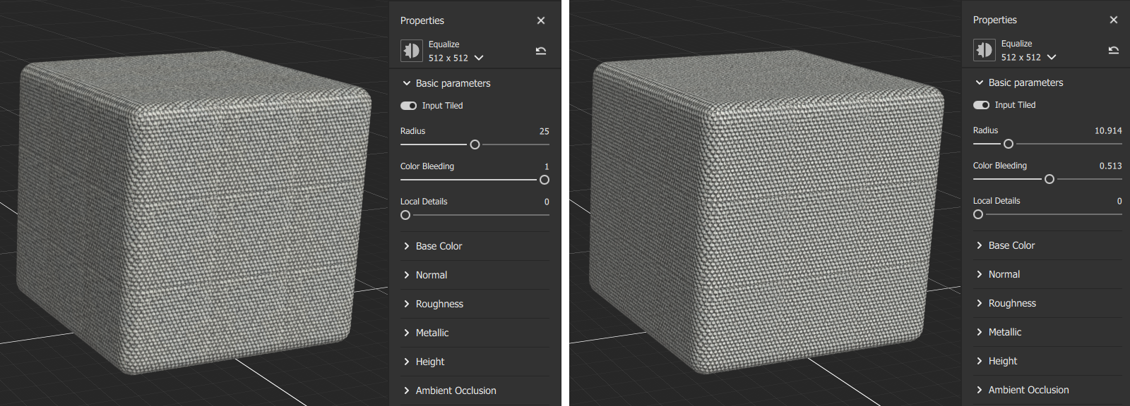 On the left, the result with the default settings of the Equalize layer, on the right after adjusting the settings.
Make textures tileable
The still visible borders between the material tiles are due to the fact that the pattern captured in the image is slightly distorted and therefore, for example, the lower edge of the texture does not fit seamlessly with the upper edge. To compensate for such distortions in a tileable pattern, we add a specialized layer. To do this, click on the + symbol at the top left of the Layers area and select Auto Tiling.
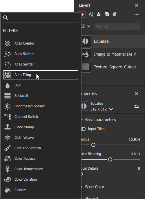 The Auto Tiling layer can analyze a texture automatically or manually and rectify it so that the texture boundaries are no longer noticeable during tiling.
Depending on the linked texture, Auto Tiling will attempt to automatically rectify the texture and identify a seamlessly tileable area within the texture. If this fails, a red warning will appear at the bottom of the screen, which you can simply close. The effect can also be supported manually by clicking on the Advanced settings button of the layer.
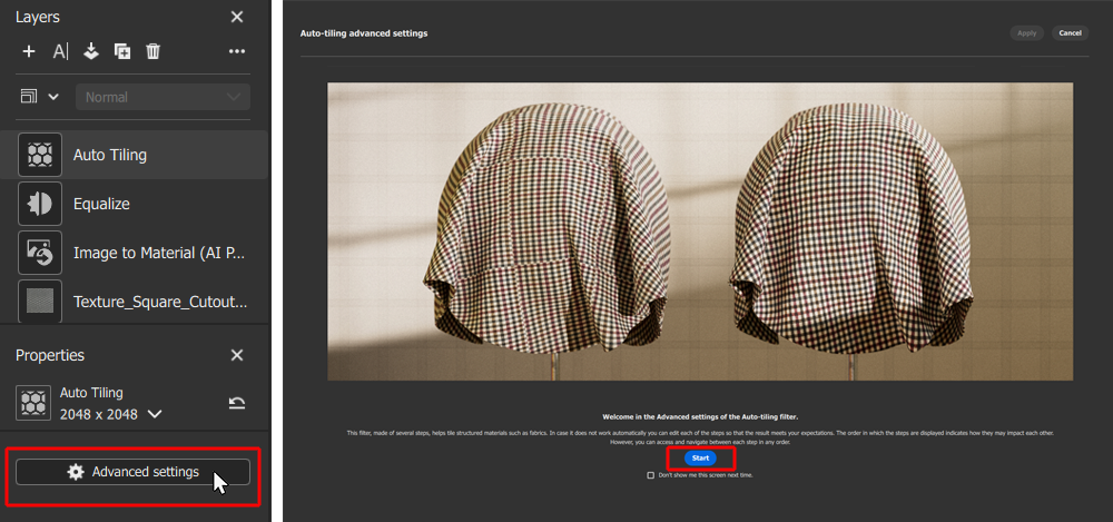 On the Auto Tiling layer, clicking on the Advanced settings button opens a guided process to detect and compensate for distortions in the texture.
Click the Start button in the introduction dialog of the Auto Tiling layer to start the analysis of the linked texture. The process begins with the selection of one of the automatically generated textures for the different properties of the material. Which material property is chosen here does not matter in the first instance. It is only important that the pattern it contains is clearly recognizable so that recurring elements can be identified (see following illustration).
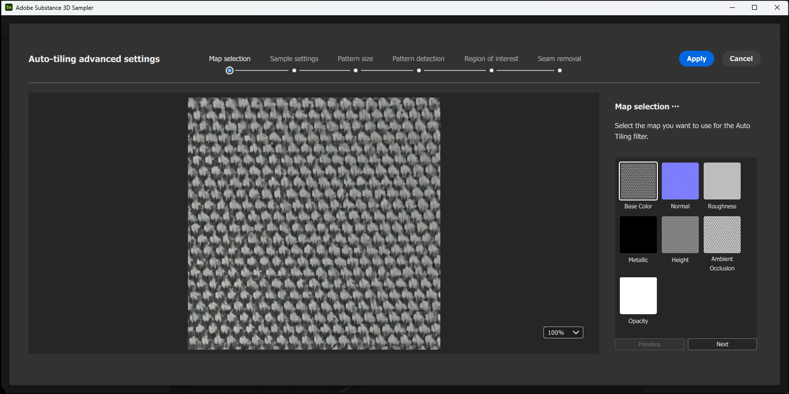 Select one of the material properties for the evaluation. By clicking on one of the image tiles in the right-hand area of the dialog window, select one of the automatically generated maps on which the structure to be tiled can be easily identified.
In our example, the map for the Base Color is already sufficient for the assessment. However, the Height or Ambient Occlusion maps would work just as well. The Next button takes us to the next preparation step (see following illustration). Three controls are available to compensate for obvious rotations of the structure as well as shearing in horizontal and vertical directions. The aim here should be to bring the structure intended for tiling into a grid of columns and rows that is as homogeneous as possible. Minor deviations from this are compensated for in the following step, which you reach again by pressing the Next button.
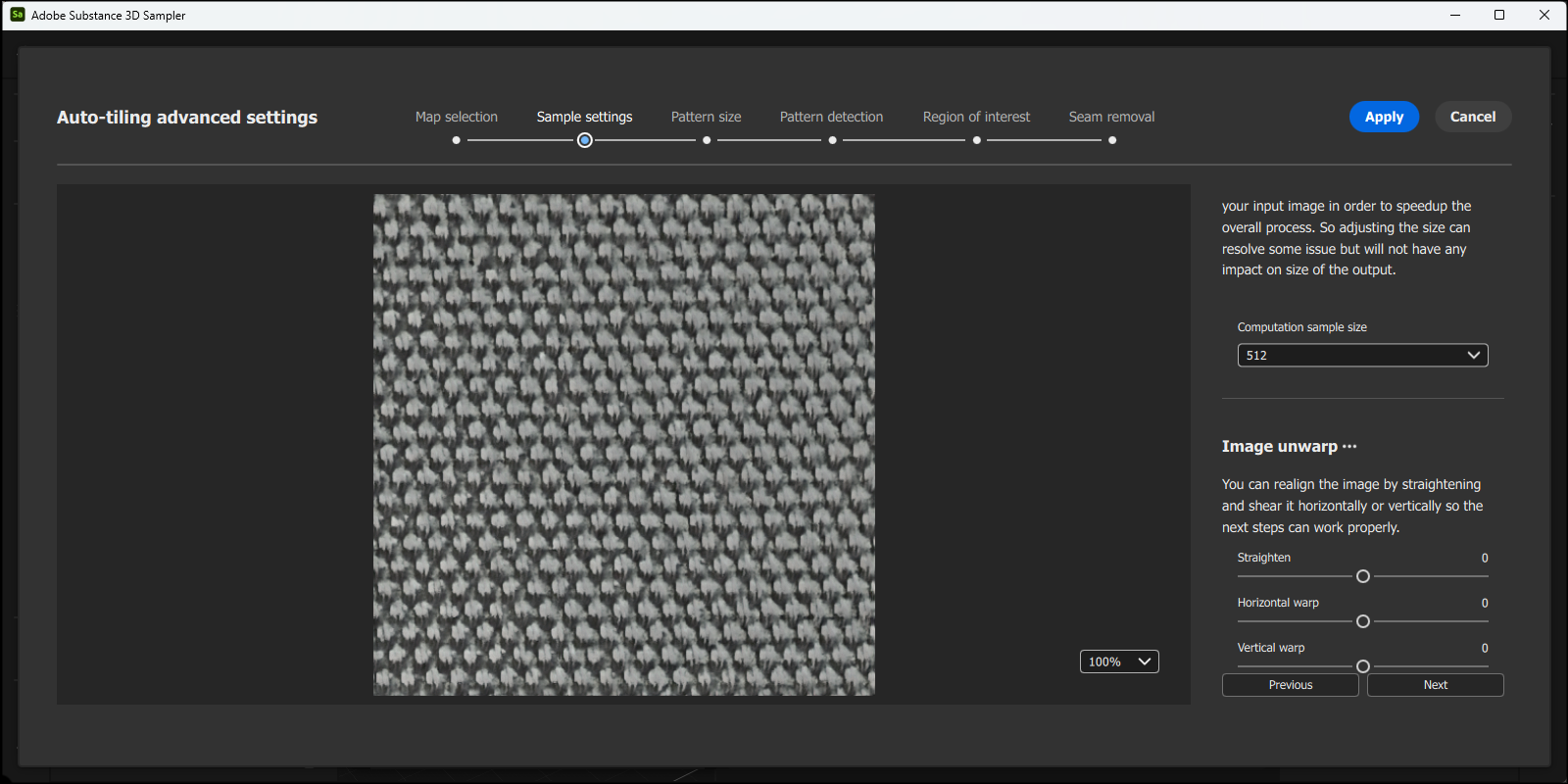 In the second step, rotation and shearing of the structure can be compensated.
In this step, repeated and similar sections of the map are automatically searched for and marked with lines. Normally you do not need to correct anything manually here, as long as the selected map was contrasty enough to recognize the structure well enough. Alternatively, you can activate the option for Custom size and use the corresponding slider to search for alternative pattern sections in the map. However, as can be seen in the following illustration, Larger size already provides good recognition of the structure in our example, which is why we leave it at that and switch to the next step via Next.
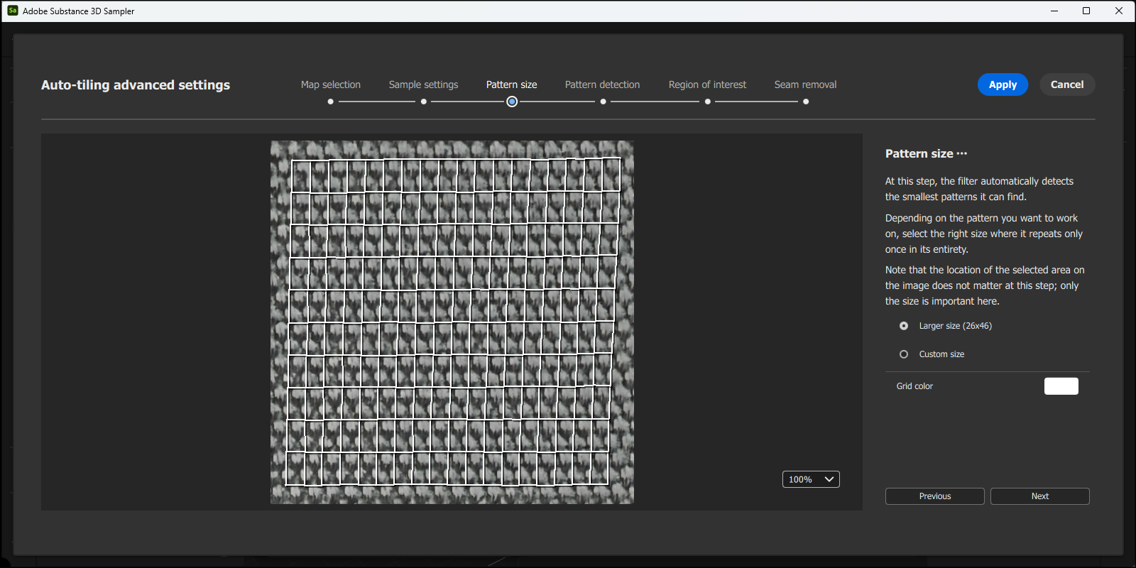 The smallest units of a repeating pattern are automatically recognized and marked by lines.
The previously automatically recognized structure is now marked by dots, which can also be moved individually with the mouse. In our case, however, we trust the automatism and therefore refrain from approaching certain areas and manually checking and, if necessary, correcting individual point positions on the grid. Instead, we move on to the next step and press the Next button again.
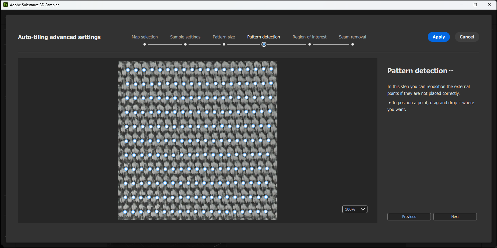 The corner points of the recognized pattern structure are marked by dots, which can also be moved with the mouse if necessary, e.g. to correct misplacements.
In the next step, the corner points of the tileable pattern are highlighted in color again. This time, however, it's about a frame that can be individually scaled to determine the position and size of the final texture tiles within the maps. We reduce this frame slightly here by grabbing and moving the thickly marked areas on the frame to gain some distance from the edge of the original maps.
Only the cells marked in blue are used to calculate the texture tiles. Since the outer edge of the maps is still based on our linked image, the alignment of the texture tiles can be slightly improved, as they are now completely inside the maps (see following figure).
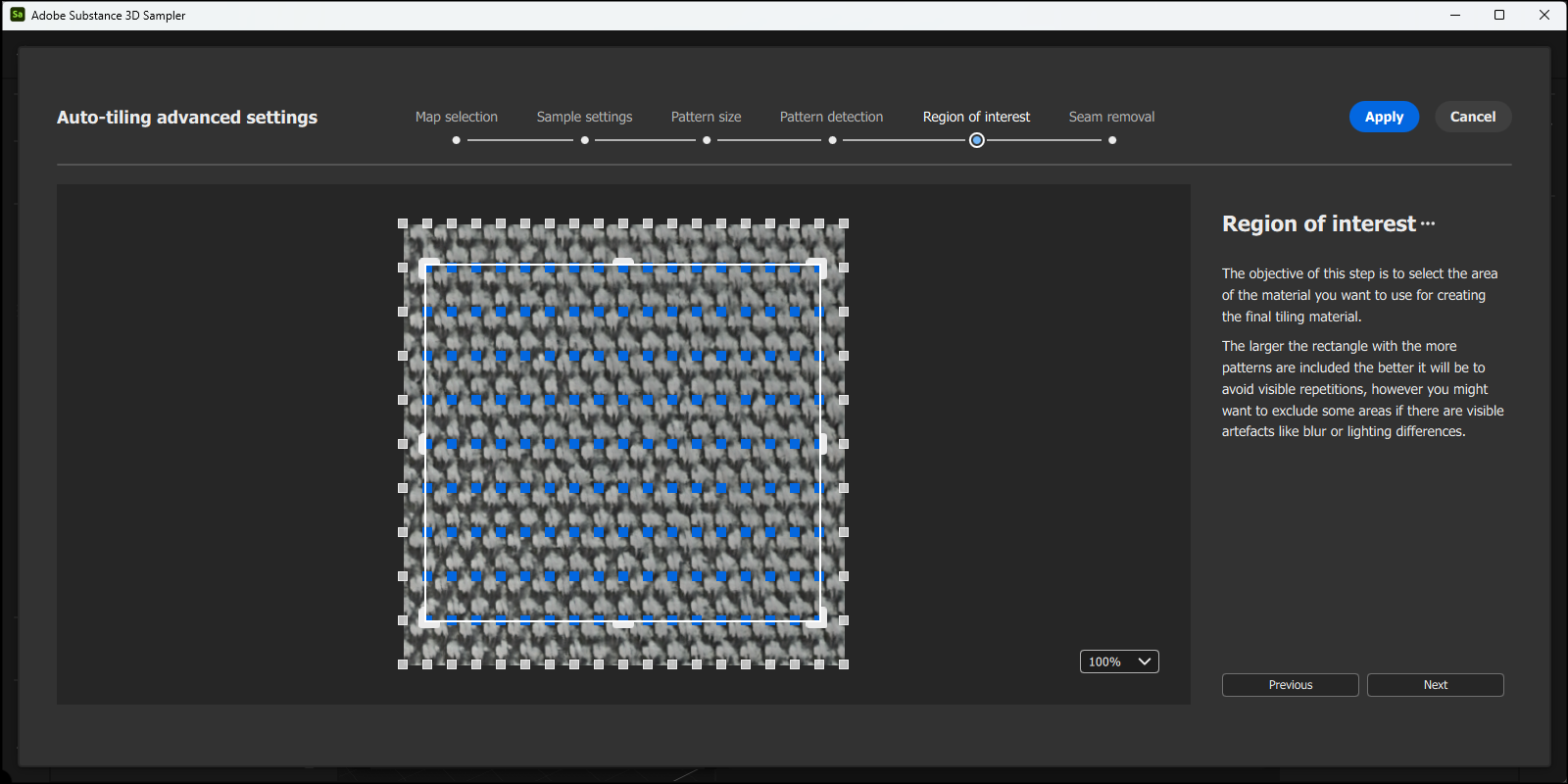 An individual frame marks the edge of the final material tile.
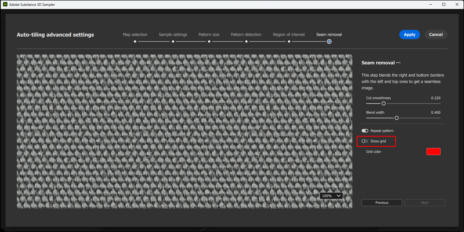
The final processing step is reached again via the Next button and now allows the material in the tiling to be inspected for the first time. Please also note the scaling factor in the bottom right-hand corner and the Show grid option. The number of visible tiles can be controlled and the standard border of the individual tiles can be hidden.
This is helpful to be able to examine the transition between the tiles, which can be controlled using the sliders provided. If you are satisfied with the result, complete the work using the Apply button. You then return to the standard interface and can inspect the corrected material on the assigned geometry.
 In the final processing step, the transitions between the material tiles can be calcualted.
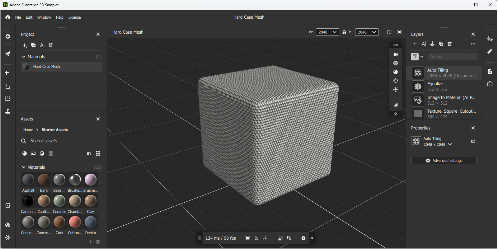 The corrected tiling of the material.
Adjusting the physical size of the material
A major advantage of Substance 3D materials is that they can be given real dimensions if they are based on image textures. This makes it easier to adapt the number of material tiles to the respective object size and thus achieve a realistic surface representation. The ruler icon on the right-hand edge of the interfaces is available for this scaling specification, as can also be seen marked in red in the left-hand part of the following illustration.
 Manual specification for the physical size of a material tile.
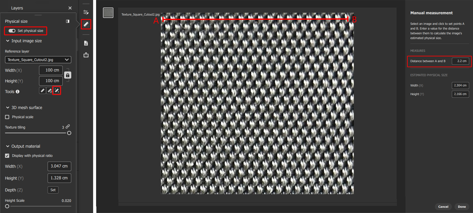
A special dialog opens where the option for Set physical size must first be activated. This is the only way to activate the corresponding input options. The third icon in Tools (see red marking in the figure above), which is used to activate manual dimensioning within the linked texture map (see right-hand side of the figure above), is particularly practical. There you can draw a line between structures whose real distance you know or can at least estimate well directly on the image texture display by holding down the left mouse button. The position and end points of this dimension line can also be edited later by dragging the end points of the line with the mouse. This line between the A and B end points is highlighted in red in the figure above.
Finally, enter the real distance between the marked end positions of the line in the right-hand part of the dialog. Please note that decimal places must be indicated by a point and not by a comma. In the best case, measure a comparable structure distance on the real material to determine this distance. In our example, we use a distance of 2.2 cm. Finally, press the Done button to return to the normal interface.
 Manual specification for the physical size of a material tile.
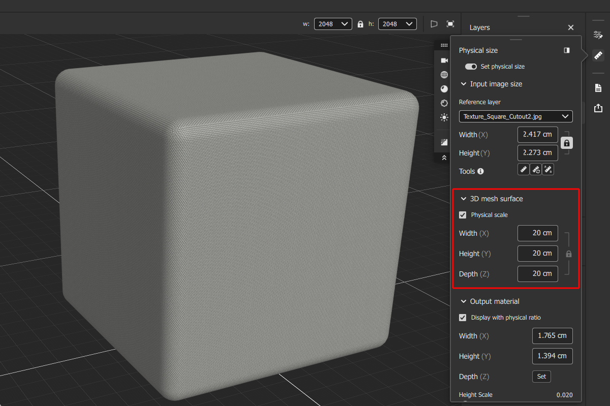
The physical size of the material can now also be checked directly visually by activating the option for Physical scale in the 3D mesh surface area of the dialog. Below this, you will find dimensions for the geometry used in the viewport. In our example, we use a rounded cube with a side length of 20 cm, comparable to the maximum dimensions of the small hard case. Accordingly, the scaling of our material representation on the cube is now adjusted so that it looks like the real hard case (see figure above).
Modify the material and reveal individual settings
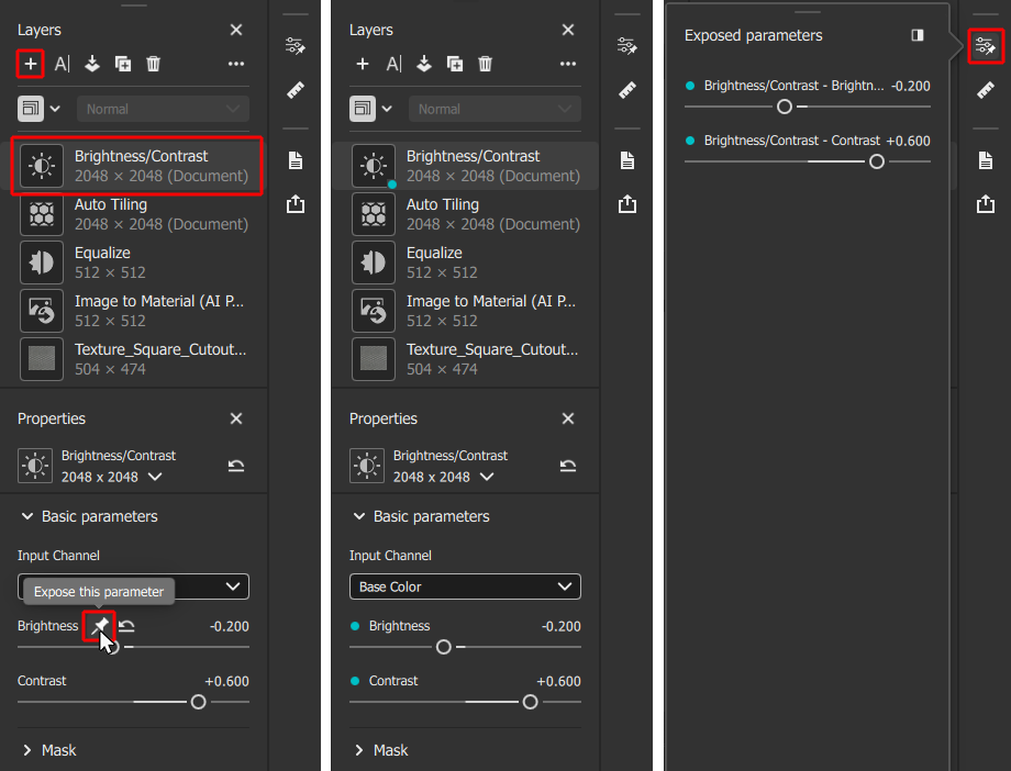
Additional layers can now be added to the material as required, e.g. to apply scratches, variations or simply color correction. To do this, we press the + button above the layer manager again and this time select the Brightness/Contrast layer to darken the material slightly using its settings.
 Manual specification for the physical size of a material tile.
As can be seen on the left in the illustration above, a pin symbol becomes visible next to the layer settings when the mouse pointer is placed next to the name of a setting. Click on this symbol to reveal the corresponding value of the material. Such settings are then marked by a bluish dot in front of the parameter name and also by a corresponding dot directly in the layer icon, as can be seen in the middle section of the above illustration. In this way, the list of layers in the manager already shows where disclosed values have been defined.
In addition, all disclosed settings are also listed on a separate dialog page, which can be opened by clicking on the slider icon on the right-hand side of the interface (see right-hand side of the above illustration). Revealed settings not only make it easier to configure the material in the Substance 3D Sampler, but are also transferred as editable settings when exporting to Cinema 4D. We deal with this in the following section.
Export the material to Cinema 4D
Now that the material has been configured satisfactorily, the physical size has been set and the settings suitable for post-processing have been revealed, it can be transferred to Cinema 4D.
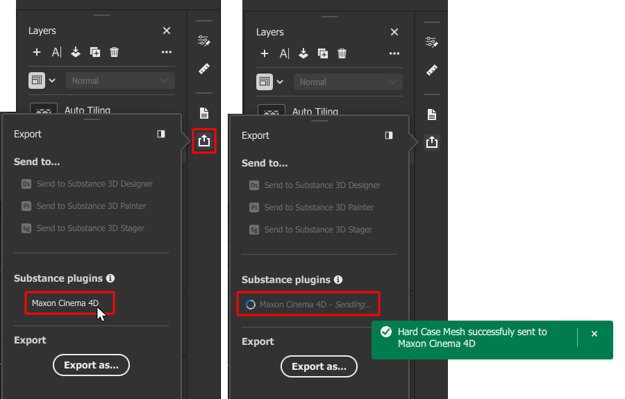 Export of Substance 3D Material to Cinema 4D.
To do this, we first make sure that Cinema 4D is running and then open the Substance 3D Sampler export settings by clicking on the corresponding icon on the right-hand side of the interface. In the dialog box that appears, we find the entry for Maxon Cinema 4D in the category for the Substance plugins (see left illustration in the figure above). The export process is then started by clicking on the term Maxon Cinema 4D. An animated process icon appears until all bitmaps have been saved and sent to Cinema 4D. You will then also receive a green notification at the bottom of the screen when the export is complete (shown on the right in the above illustration).
In Cinema 4D, the usual warning appears when loading an asset that uses external files (in this case bimap textures), which you can use to select the location of the Substance 3D Material. If a project is already open in Cinema 4D at the time of export from Adobe Substance 3D Sampler and has already been saved, a copy of the material can be created directly in the tex folder of the project by clicking Yes. Otherwise, if No is selected, only global file paths are used for the material and its textures. However, you can also convert these into local paths later using the Project Asset Inspector, which makes it easier to archive and pass on the project.
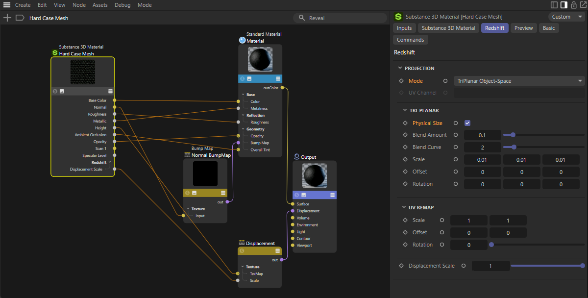 Adaptation of the imported Substance 3D Material so that the physical size is evaluated.
Within Cinema 4D, the imported Substance 3D Material appears in the Material Manager as usual and can be assigned to any objects in the scene from there. Of course, you can also open the Node Editor for the material as usual to make individual adjustments, e.g. by activating additional material properties or controlling material properties via additional shaders or textures.
This can also include switching the projection mode if you want to set the physical size of the Substance 3D Material in Adobe Substance 3D Sampler and also use it in Cinema 4D.
To do this, select the Substance 3D Material node in the Node Editor and navigate to its Redshift settings (see also the figure above). Alternatively, you can simply select the material in the Material Manager and then select the Redshift tab in the Attribute Manager.
You will find the Mode menu in the Projection group, which you must use to select one of the TriPlanar options. In most cases, this will be TriPlanar Object Space. This is the only way to make the Tri Planar settings group visible, in which the option for the Physical Size can then be activated. From this moment on, the material is always displayed in the correct scale on the objects, regardless of their size.
Below you will find a simple example scene with the Substance 3D Material discussed here. This is a project with separate assets, which is why this file must first be unpacked after downloading before it can be opened in Cinema 4D.
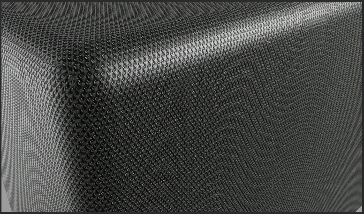 Detail rendering of a rounded cube with the assigned Substance 3D Material based on a simple mobile phone snapshot.