Tag properties
Many of these settings should be familiar to you from the Cloth tag's Surface tab. These work exactly the same here.
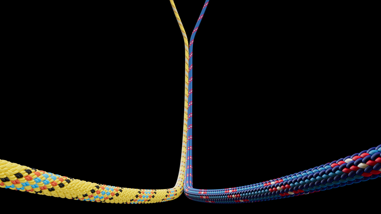
 With precise collision detection, even ropes can be wound from splines.
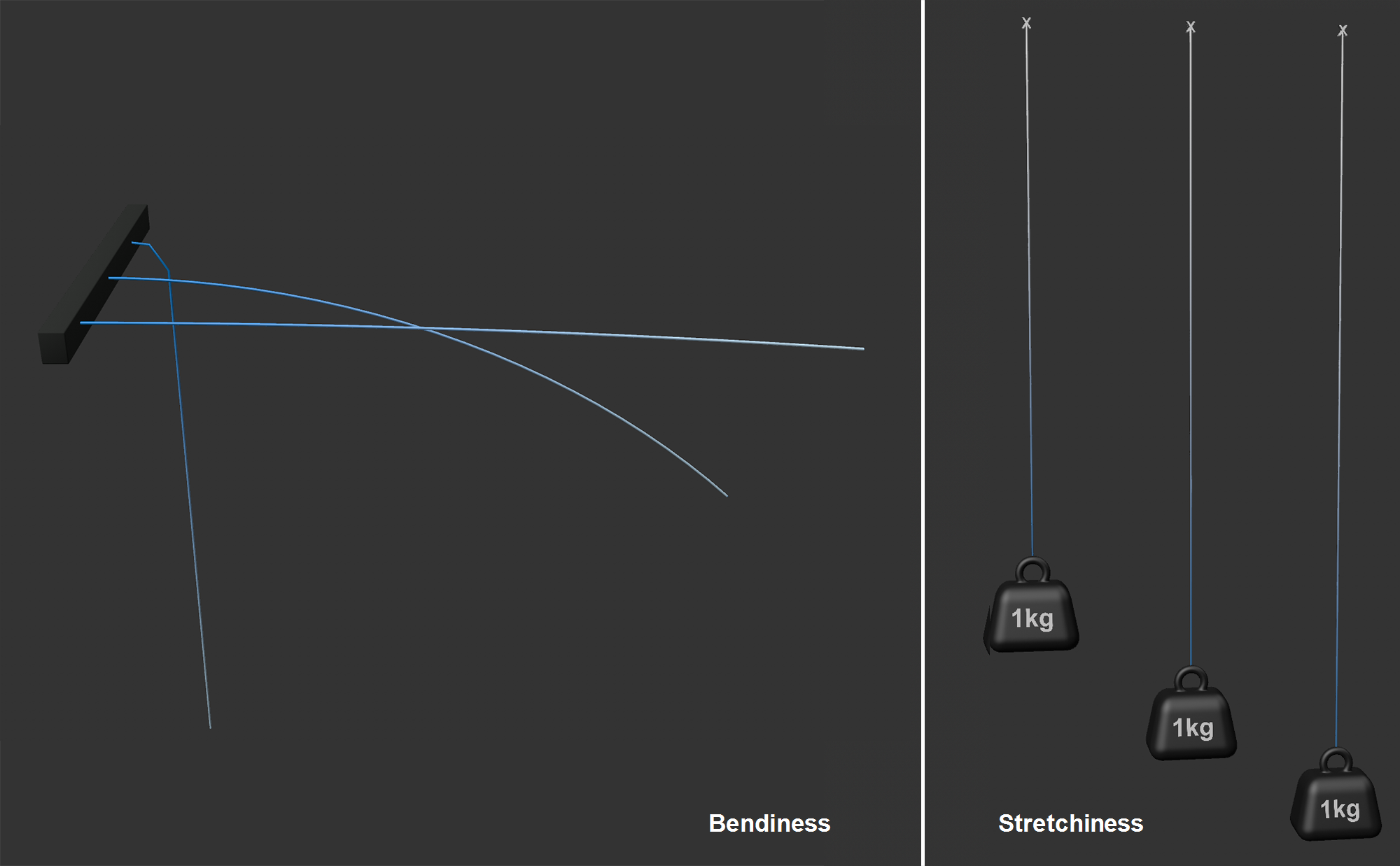
 The two parameters Bendiness and Stretchiness each with increasing values.
This allows you to control how easily splines "bend" at their points, i.e., how easily edge angles can deviate from their initial state. The larger the value, the easier the spline will bend. The type of behavior ranges from a thin stick (very small value) to a rubber hose, a rope or a bicycle chain (large value).
Bendiness also depends on the Substeps parameter in the Preferences menu. The larger the Substeps, the stiffer the spline will be (see also Tips and Tricks).
Map lets you use vertex maps that define point-level Bendiness. If you define a maximum value for the related parameter, the vertex map will use exactly this value at 100% weighting, half of it at 50% and so on.
If this option is enabled, the spline will also be stiffened with regard to twistability along its path. Imagine a helix-shaped spline that is deformed along its long axis. If Torsion is enabled, a spring force analog to a spiral spring will result - while maintaining the shape of the spline - which is controlled by the value defined for Bendiness. Both of these are defined together using one setting.
Note that too many spline intermediate points will weaken the effect.
This controls how far the spline can stretch between each of its points compared to the initial length. The behavior with regard to defined values ranges from metal (small value) to very stretchable rubber (large value).
Map lets you use vertex maps that define Strechiness at the point level. If you define a maximum value for the related parameter, the vertex map will use exactly this value at 100% weighting, half of it at 50% and so on.
When collisions occur, this setting defines a "spring-back" force in the direction of the contact point Normal. If, for example, a rope falls parallel onto a plane, it will repel slightly if higher values are used. It will repel slightly from the surface.
Be careful with very high values here, otherwise faulty behavior may occur.
Map lets you use vertex maps that define the feather Thickness at the point level. If you define a maximum value for the related parameter, the vertex map will use exactly this value at 100% weighting, half of it at 50% and so on.
When a spline touches another collision object (e.g., another spline with a Rope tag or objects to which a Collision/Cloth tag has been applied) Friction comes into play. This is a measure for the resistance elements have when they rub against one another. Smaller values define correspondingly less friction and larger values increase the friction accordingly.
Contact or collision occurs whenever points, triangles or edges approach closer than defined under Radius.
Map allows you to use vertex maps that define Friction at the point level. If you define a maximum value for the related parameter, the vertex map will use exactly this value at 100% weighting, half of it at 50% and so on.
 Here 2 splines stick together after touching.
If you want to glue your splines to meshes or other splines, this is the right parameter. Make sure that enough points contact each other so the bounciness works best. Subdivide your spline, if necessary (e.g., with Interpolation). For more stickiness, higher values such as 500 might work better.
Map lets you use vertex maps that define Stickiness at the point level. If you define a maximum value for the related parameter, the vertex map will use exactly this value at 100% weighting, half of it at 50% and so on.
When a constraint is created (usually image 0 at the beginning of the simulation), when the rope or spline is still in the initial state, each constraint has a very specific length. The rope will attempt to maintain these lengths in order to also maintain the overall rope length.
The rope length can now be defined in its length as a percentage or it can be animated. The rope will then shorten or lengthen accordingly.
Map lets you use vertex maps that define the Target Length at the point level. If you define a maximum value for the related parameter, the vertex map will use exactly this value at 100% weighting, half of it at 50% and so on.
Radius works similarly to Thickness for the Cloth tag, except that here a radius is formed around the spline, below which approaching collision elements (object points, edges, triangles, splines) will be called up for collision.
A very important setting if you want to avoid penetrations. In order to avoid this, collisions should always occur before the geometry actually meets (which is why the default setting is 0.5 cm).
If you want to use a very small Radius for visual reasons - for example, to avoid objects hovering over surfaces as much as possible - it may be useful to increase the Intermediate Steps setting in the Simulation Project Settings. This lets you calculate collisions more precisely for faster movements.
If you have very strongly subdivided splines, it can happen that point distances turn out to be smaller than twice the Radius, which would trigger a permanent collision. What you want to avoid: Internally, Cinema 4D will automatically select a smaller radius for the respective points (40% of the shortest edge attached to this point). This means that the defined Radius value is not fixed but can be undercut depending on the distance between the spline points. This applies to self-collision and collision with other Cloth objects/splines. However, the defined Radius value always applies to Collision objects (Collision tag, Rope Belt).
Map lets you use vertex maps that define the Radius at the point level. If you define a maximum value for the related parameter, the vertex map will use exactly this value at 100% weighting, half of it at 50% and so on.
Here you can define the total mass of the spline, which will be distributed evenly to all points. Higher masses develop more "thrust" when colliding. In other words: you have greater inertia.
Map lets you use vertex maps that define the Mass at the point level. If you define a maximum value for the related parameter, the vertex map will use exactly this value at 100% weighting, half of it at 50% and so on.
Damping
You can already find an attenuation setting in the project settings (Damping), but this applies to the entire scene. The following settings can be used to define the damping per vertex map down to the individual spline points.
Damping is nothing more than an artificial removal of kinetic energy from a simulation.
With increasing damping, the spline assigned to the tag behaves more and more as if it were moving in increasingly viscous media (from air -> water -> honey etc.).
Activate this option if you want to set the damping at tag or object level. Otherwise the global Attenuation will apply (see previous paragraph).
Enter a maximum level of damping here, which can be adjusted at point level using a vertex map in the following Map field. Without a vertex map, the Strength will be applied to all spline points.
With increasing values, points will correspondingly slower - as with movement in air -> water -> honey etc.
Values greater than 100% are possible.
Place a vertex map here if you want to define damping at point level. Set a maximum value for Strength. With 100% vertex map weighting, the corresponding point is assigned exactly this maximum value; with smaller values correspondingly less.
Please note that a 0% weighting will result in the following parameter Min. Starch defined starch is used.
If you have placed a vertex map under Map, the setting here defines which damping level corresponds to 0% weighting.
This simplifies the drawing of the vertex map, as you usually operate with 0% and 100% values here. You then do not have to set intermediate values such as 2% in the Paint tool.
Splines can also tear if the distance between their points exceeds a certain limit (Tear past). The tear will always take place at a spline point.
Provided the previous Tear option is enabled, this value specifies the allowable strain factor for each intermediate spline segment. If the intermediate segment is 5 cm long at the start of the simulation it can be stretched to 7.5 cm at a value of 1.5 without tearing. If the stretch is greater, the spline will split into two sections.
With Map you can use vertex maps that define Tear After at the point level. If you define a maximum value for the related parameter, the vertex map will use exactly this value at 100% weighting, half of it at 50% and so on.
For example, if you want to tear a spline, set Tear After to 90%, for example. Without a vertex map, the spline would immediately disintegrate into its individual parts. Therefore, a vertex map must ensure that all points that have to hold have a 0% weighting, while a 100% weighting is at the loation of the tear, for example.
If you use the following buttons to fixate selected spline points, this option can be used to color the fixated points.
Allows you to set spline anchor points - these are fixed and do not move. Use the Set option to fix the selected spline points. Release does just that for the selected points. Delete removes all anchor points.