Simulation
Most of the following settings can be animated. This makes it possible to adapt the settings to different phases of the simulation. You can, for example, increase render-intensive settings such as Substeps or Iterations if this is really needed and, for example, in phases in which no collisions take place, these values can be lowered in order to speed up the simulation.
This parameter is crucial for the precision of the simulation. The higher the value, the more precise the calculation will be and the more precisely the collision detection will be (with correspondingly longer calculation times).
Each animation frame is internally divided temporally with the Substeps specified here. A simulation algorithm (calculation of the constraint effect, object positions and velocity, etc.) will be run for each substep.
Especially in the case of penetrations at high speeds, you should increase this value. Imagine an object traveling at high velocity that collides with a hanging cloth. Assume the object is to the left of the cloth at frame 12 and to its right at frame 13. Cinema 4D would not detect a collision (if Substeps is set to 1). With multiple Substeps that, for example, calculate frame "12.2" and "12.3", the collision would be detected and calculated correctly.
This is a disadvantage: Substeps (and Iterations) have an influence on the stiffness of the clothing objects to be simulated. The larger the Substeps/Iterations, the stiffer the cloth will be (i.e., the more precise the bendiness/stretchiness will be).
Simply put: applying a large number of Substeps and iterations will produce a correspondingly more realistic result. Most often, these values have to be kept low to keep the calculation velocity manageable. This means that the solver, which has to take innumerable constraints into consideration, makes shortcuts and deviates from a realistic result. This deviation is primarily noticeable in the lack of stiffness (= rubber-like behavior), but possibly also inaccurate collisions, etc.
Note that very high values (e.g., 200) may cause paradoxical behavior: instead of precision increasing, it decreases. The reason for this is the 32-bit precision of the GPU Try instead increasing the following Iteration setting - in stead of Substeps. See also Tips and Tricks for additional measures that can be taken.
Internally, an iterative algorithm is used that approaches the mathematically(!) optimal final result (= all constraints are met) as closely as possible. Iterations define how often the numerous constraints are calculated per Substep.
The practical impact, for example, on clothing behavior is: the fabric becomes stiffer - because constraints hold better.
Higher values can help to avoid dot jitter.
See also previous parameter Substeps, both settings are closely linked and have similar effects.
If you set Iterations to 0, a different solver is used internally, which converges more slowly than the standard solver, i.e., in a figurative sense treats the constraints somewhat more laxly. The Smoothing Iterations will be set to 1.
This allows you to achieve greater robustness and homogeneity of the simulation. However, cloth and ropes will then be more stretchy.
Especially in simulations with many constraints that sometimes work against each other - e.g. constraint A wants to move a point to the left, constraint B to the right - this can lead to point jitter (see also next paragraph). In such cases, the other solver can produce better results.
To compensate for the greater, more rubbery ductility, it is recommended to increase Substeps.
Avoiding jitter.
The following two settings are primarily used to reduce jitter that occurs in small areas.
In general, it can also help reduce Substeps and increase Iterations.
The internal point calculations due to the various constraints "tugging" on them can result in large point deviations, which can give the impression that additional, sudden impulses are occurring.
With Smoothing Iterations > 0, additional averaging calculations are performed, whereby this effect loses its effect, i.e., there is less jitter.
Only use this parameter if it is necessary, as it can result in side effects such as changing stiffness.
Using this setting, velocity / energy can be removed from the system. Smaller values of up to 3% are recommended. Higher values will make the simulation look correspondingly more like it were under water.
Simulations tend to "explode" occasionally, this can be countered by carefully increasing this value.
You can also define damping values - here even separately for linear and rotary movements - at the corresponding tag level (e.g., Override)
These two settings are primarily used to prevent unstable simulation states - which could culminate in a simulation freeze. Excessively high velocities or accelerations (both on point level) are limited. This helps reduce collisions and avoid penetration that would otherwise require prohibitively high values for the Passes and/or Substeps settings to achieve the same effect.
We should also mention an effect called "TDR (Timeout Detection & Recovery)", an operating system protection mechanism that stops the simulation with an error message when the graphics card is overloaded. This effect can also be reduced by both settings.
The two methods have the disadvantage that the simulation runs more stable, but this is at the expense of realism, because the whole simulation is damped.
Then use:
-
Velocity Clamp: this mode is appropriate when objects are simply moving at very high speeds without (or only small) accelerations.
-
Acceleration Clamp: if there are penetrations in collisions, which can look like sudden point jumps (= high acceleration) there, this option is the right choice.
Note the fundamental difference between Velocity Clamp and acceleration: in the former case, the velocity is actually effectively limited, while in the latter, although there is no acceleration growth, there can still be velocity growth (as long as there is - positive - acceleration, so long the velocity grows).
For Velocity Clamp: You have the following options:
-
Off: No velocity is clamped.
-
Scene Scaling: Is limited to a percentage value of the speed that depends on the bounding box of the largest object present in the scene or Simulation Scene object. The velocity is applied globally.
-
Absolute: Velocity is limited to the absolute point speed. The velocity is applied globally.
-
Collision Radius: This is limited to a percentage value of the velocity that is dependent on the respective collision radius (thickness or radius) around each point. Since thickness depends on the mesh density on the one hand and can be controlled via Vertex Map on the other, the velocity per point can differ. This means that the velocity for very low thicknesses is capped locally more strongly.
This is not that easy to understand. In principle, you define the maximum allowable velocity that is dependent on certain factors.
From Bounding Box
Define here the maximum allowed velocity if you have set scene scaling above.
Size
Define the maximum permissible velocity here if you have set Absolute above.
Radius
Here you can define the maximum permissible velocity here if you have set Collision radius above.
For Acceleration Clamp you have the following options:
-
Off: No acceleration is clamped.
-
Scene Scaling: Is limited to a percentage value of acceleration that depends on the bounding box of the largest object present in the scene or Simulation Scene object.
From Bounding Box
Here you can define the maximum allowable acceleration if you have defined Scene Scale above.

Collision detection is immensely important; firstly, it looks unsightly when penetrations occur, and secondly, once this has happened, the penetrated areas adhere tenaciously to each other and are difficult to separate. For this reason, there is a whole series of separate settings below that only affect the collision and can be calculated more quickly than setting up Intermediate Steps and Iterations, which are very computationally intensive and also significantly change essential properties such as textile stiffness.
These collision settings refer to internal calculation processes and sound complicated in the description - and in principle they are, although already described as simple as possible. Generally speaking, the values should be increased carefully if collisions are problematic.
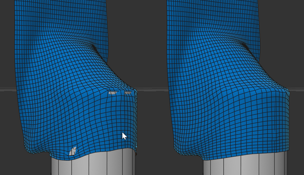 A fast moving textile collides with a cylinder, with Passes 0 there are penetrations on the left hand side, on the right hand side there are no penetrations with a value of 5.
This defines how often a collision detection is performed per animation frame. If a collision is detected, collision constraints are generated dynamically and temporarily (the precision of which can be controlled with the next 2 parameters), which then ensure that the tag-carrying object cannot penetrate other - or even its own - collision geometry.
If you define a value of 1 here, a collision detection is performed at the temporal beginning of the simulation frame. Any collision constraints generated in the process are retained until the next collision query and are taken into account and evaluated for each Intermediate Step.
Especially for fast, rapidly rotating or generally non-linearly moving geometry, increasing this value can be advantageous. For just about any penetration, increasing the Passes can be helpful.
Make sure that Substeps is not smaller than Passes, otherwise nothing will happen.
By means of this parameter, additional iterations are performed only for the pre-existing collision constraints found previously by Passes and End Frame Pass. This also helps avoid collisions.
Make sure that before you increase Passes, End Frame Pass and/or Substeps, try enabling this option here first. This may be all that's needed. Additional Iterations can be calculated relatively quickly.
This parameter inserts additional collision queries at the end of the simulation image, when all new point positions have actually already been calculated. This is to prevent existing penetrations (which initially slip through the algorithm's fingers) from being present at the start of the calculation of the next simulation image, which has a problematic effect on the simulation. For each process, the newly discovered collision constraints will be calculated multiple times (as often as is defined under Iterations).
Note that only small values in the range of 1-3 provide a benefit.
You could alternatively increase the Passes value but End Frame Pass is usually faster.
Especially also with moving collision objects, increasing End Frame Pass (and also Extra Iterations) can lead to better results.
Restrict Movement on Contacts and Collision Priority are two additional methods that help you to improve and, in the best case, avoid penetrations in the event of collisions.
First of all, the Restrict Movement on Contacts: what happens here? "Forbidden movements" - which would lead to the penetration of e.g. collision objects or other simulated objects (e.g. clothing, ropes, rigid bodies etc.) are simply cut off.
In itself, this is a major intervention in the simulation, as movements/speeds are simply set to 0, which practically destroys energy. This can lead to unrealistic behavior. However, preventing penetrations is often the top priority, so this can be accepted depending on the application.
Here you have the choice of what the functionality just described should affect:
- Collision objects: only collisions between simulated objects and collision objects (i.e., objects with a Collider Tag) are taken into account. So if you only attach importance to the collision with collision objects, leave this option activated.
- All: like collision objects, except that collisions between simulated objects (e.g., between Rigid Body and clothing/ropes) are also taken into account.
Please note that Restrict Movement on Contacts cannot work miracles and does not prevent penetration in every case. It can therefore also make sense to combine movement limitation with collision priority.
The following applies to movement limitation: Collisions with fast-moving collision objects hardly benefit at all.
For collisions of the simulation system, a basic distinction must be made between 2 types of collision:
1. Collisions of simulated objects (e.g. B Objects with Cloth or Rigid Body Tag) among each other.
2. Collisions of simulated objects with collision objects (i.e., objects with a Collider Tag).
These two collision types, if they occur simultaneously on an object, can specify contradictory positions. What happens in such a case? To put it simply: until now (before Cinema 4D 2025.1), both collision types were calculated independently of each other for each individual contact and the average was simply used for the Rigid Body or point position. Both types of collision were considered equally. This often works well, but sometimes it doesn't, and then penetrations occur, for example.
Watch the following video:

Several cubes, heavy due to their increased mass, collide with an elongated cube, referred to below as a 'board', and a sphere. The cube and board are Rigid Bodies, the sphere is a collision object. With the preset settings, the board penetrates the sphere with the left hand. Why? At the moment of contact, there are many collisions between the cube and the board (1. Collision type), but only very few between board and sphere (2. Collision type). However, since all contacts are treated equally, there is a strong preponderance for the cube-board collisions and the board is pushed through the collision object.
On the right-hand side you can see the effect of the Collision Priority: the two collision types can be weighted differently - even infinitely: should the focus be on Collision Type 1 or Collision Type 2? The problem lies in the collision with a collision object, so the 2nd collision type (simulated objects (board) with collision object (ball)) was preferred on the right by setting Collision Priority to Colliders: the board collides correctly with the ball and remains on it.
The following options are therefore available for Collision Priority:
- None: the legacy mode (before Cinema 4D 2025.1), both collision types are calculated with the same priority.
- Collision objects: priority is given to the collision of simulated objects with collision objects. Select this mode if there are intersections in collisions between simulated objects and collision objects.
- Dynamic objects: priority is given to the collision of simulated objects with each other. Select this mode if there are intersections between simulated objects.
If the previous parameter was about which collision type should be preferred, Collision Priority specifies the way in which the priority should be calculated.
There are 2 options:
- Extra Pass: qualitatively the best solution, but it costs more computing time than Split Average. At the end of the collision calculation, an extra calculation step is performed for the preferred collision type.
- Split Average: Faster, but less precise than Extra-Pass. This can be used to weight between the two collision types. First, all results of one collision type are averaged and then these two results are included in the overall calculation by means of eighting. With a weighting of 50%, both collision types are included equally in the calculation, regardless of how many collisions there are for each type. If you increase this value, the weighting shifts towards the type set under Collision Priority.
In the following example on the right, you can clearly see how the Split Average ensures that Rigid Bodies barely penetrate the plane. Left Collision Priority switched off.
Play around with the Weight parameter and see how the penetrations decrease with a higher value. Due to the priority shift, it is quite possible that the fragments penetrate each other, but this is hardly noticeable given the number of fragments.
For more complex scenes, you should always try out the divided average first, as the calculations are faster here.
When calculating simulations, there is often the problem that simulations are calculated too similarly. Imagine 10 identical balls rolling down a plane in parallel: with exactly the same settings, they all follow a parallel but identical path. This has little to do with reality, because there are irregularities everywhere that influence the trajectory, e.g. one ball is a fraction heavier than the other, there is a small depression in the floor, etc. Except under laboratory conditions, there will always be irregularities.
Please note that, for example, rolling or sliding objects constantly cause collisions and the collision noise therefore has a constant effect - and not just superficially at the start of a simulation.
In general, you should use smaller values in the low, single-digit percentage range for Rigid Bodies; higher values are usually possible for clothing simulations.
Example
In the scene above, a series of balls are rolling down an inclined plane. Left hand Collision Noise = 0%, right hand = 2% (here the collision effects are varied, resulting in uneven running).
How does the whole thing work? The Collision Noise adds a random vector to each collision calculation. The higher the value for Collision Noise, the greater the random vector. Increasing values lead to increasingly chaotic behavior. 0 switches off the Collision Noise.
This Collision Noise is effective with every collision of the simulation, with Cloth, Ropes, as well as with Soft or Rigid Bodies.
With these settings you can display some simulation elements. These only have informational purpose The Draw option can be used to enable or disable the display configuration for the following settings.
Note that the elements are actually displayed only when the simulation is started (normally therefore from Frame 1).
Use this to display the simulated object points. The collision radius (Thickness or Radius for meshes or splines) will also be displayed.
Here, the collision radius defined by the Thickness setting can be displayed for most collision-capable Simulate objects. For Cloth, Soft Bodies, etc. these are displayed around each mesh point, while for Rigid Bodies the collision shape plus the added Search Radius will be visualized.
This option is intended for splines with a Rope tag. A green vector will be displayed between each spline point. The stronger the internal spline constraints are, the less the vectors will deviate from the alignment of their neighbors during the simulation (pay particular attention to the Curly option).
This allows the structure-preserving stretch constraints to be displayed. These always run between neighboring object points and connectable (see also Quad Diagonals) diagonal connections.
This - admittedly not all that informative mode - shows the bending constraints that ensure that a clothing object does not simply collapse in on itself, but that angle changes between polygons are opposed by some resistance.
By means of this option, Pole constraints (even if they are disabled in the Soft Body tab) can be shown. If Poles should tear, this will also be depicted by hiding these Poles; the Draw option should be disabled.
This option can be used to show connector constraints (even if they are disabled in the connector tag or no connector tag is selected). If Poles should tear, this will also be depicted by hiding these Poles; the Draw option should be disabled.
This is used to mark the center of mass for Rigid Bodies with a small axis system. This is where the weight force takes hold. The center of mass can be freely positioned in the Rigid Body settings.
At Collision Shapes, for example, a quickly computable substitute collision form can be specified. This option displays the active collision shape in the view. If Rigid Bodies are deactivated, their shape will be displayed in black.