Object Properties
Objects
Polygonal Objects
Splines
Particles (Cinema 4D)
Particles (Thinking Particles)
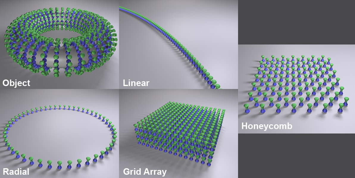
Linear Mode
The Step Functionality
Radial Mode
Grid Array
Honeycomb Array mode
The available modes all have their own corresponding settings, which will be displayed for the mode selected.
When in this mode, a Cloner’s children will be assigned to other objects. There are two methods that can be used to tell the Cloner on which object clones should be generated:
- Make the Cloner Object a child of the shaping object.
- Place the shaping object into the Object text field.
If both of the above-mentioned conditions are true, #2 will receive priority.
The clones will be assigned as follows:
- Polygonal objects: Vertices, edges, polygon center, randomly arranged onto an object’s surface, selections.
- Splines: Along the splines.
- Particle emitters or Thinking Particles particle groups: Onto the particles.
- Matrix Objects: A clone will be positioned onto each vertex of the matrix.
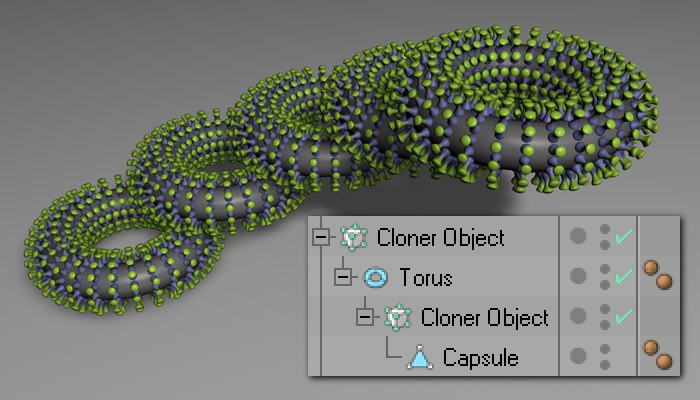
A Cloner will also function if it is itself a child of a polygon object, spline or emitter. In the case of the emitter, the Object text field should not contain any object. Even Cloner Objects within a hierarchy can be cloned, e.g., if the hierarchy below is used:
When in this mode, a clone’s child objects will be arranged linearly (can also be curved), originating from the Cloner. The clone’s Position, Rotation and Scale settings can be modified which will cause the child objects to move accordingly.
Selecting this mode will arrange a clone’s child objects circularly around the center of the Cloner.
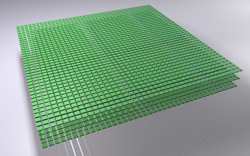
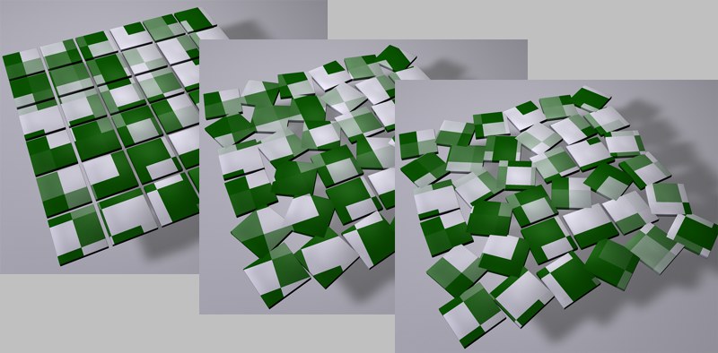
Selecting this mode will arrange a Cloner’s child objects in a grid-like manner. This can be used to achieve effects such as the one below:
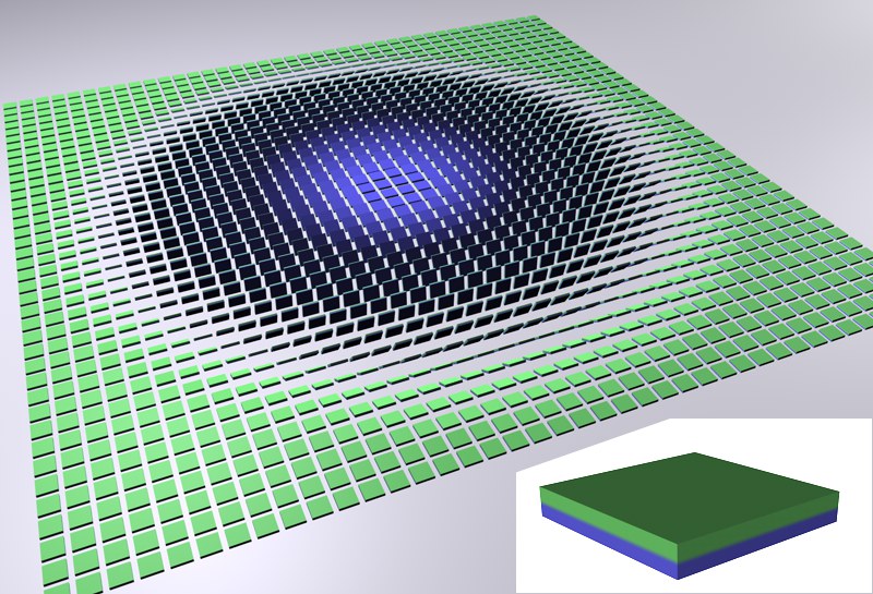 The object (insert) was cloned and its rotation varied in the Grid Array mode.
Some very nice effects can be achieved by letting an Effector fly through such an arrangement of clones.
Since using Grid Array can generate very many objects, thus slowing the editor view, the following Cinema 4D level of detail settings can be used:
- Editor view: Options / Level of Detail
- various tag. Assign the tag to the Cloner.
This mode creates a simple grid in which every other row is offset horizontally so individual clones are positioned at the center of the clone lying above it. A honeycomb pattern will be created, which can, for example, be used to create brick walls or similar patterns.
These functions are the same as described under Linear Mode.
These functions are the same as described under Linear Mode.
These functions are the same as described under Linear Mode.
Clones are exact duplicates of the objects they clone. They require just as much memory as if each clone existed as a separate object. Nothing else happens if the Cloner objects are made editable - a corresponding number of complete objects will be generated.
See Render Instance.
Principally, the same properties apply for this mode as for the Render Instance (as well as the restrictions in particular). In addition, clones will be handled as a single object internally, which reduces memory requirements and optimizes speed. This mode is particularly suited for all types of vegetation, e.g., when cloning tens of thousands of trees or clumps of grass.
For example, surprisingly fast navigation speeds can be achieve in conjunction with ProRender preview renders. In the following example, for example, fluidly navigating the ProRender preview was easily done:
 Ca. 10,000 palm trees, each with 60,000 polygons.
Multi-Instances work best if each instance is made up of as few objects as possible.
Does it still make sense to use the Render Instance mode? Yes. This can still be seen as a safety net. If Multi-Instance produces unwanted behavior - e.g., if a certain function doesn’t work as it should - you can use Render Instance.
Several simplifying - and accelerating - Viewport Modes are available. The render result is not affected.
The following modes are available (the speed of navigation slows from to to bottom of the list):
- Off: No instances will be generated
- Points: Instance positions will be displayed using small points
- Matrix: The instance positions will be displayed using small cubes (as with the Matrix object)
- Bounding Box: The instances are shown with their bounding boxes, which makes it possible to estimate the clone sizes
- Object: Instances will be shown completely
Enable this option if the objects generated by the Emitter should be optimized with regard to memory usage, i.e., an almost infinite number of renderable should be rendered. For Clones that are nestled in one another, this option only needs to be enabled for the Parent Clones of the objects to be cloned.
The Seed value affects the random dispersion of velocity. Different Seed values result in different random velocities.
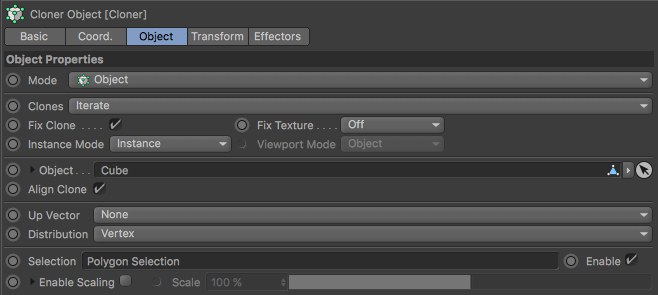
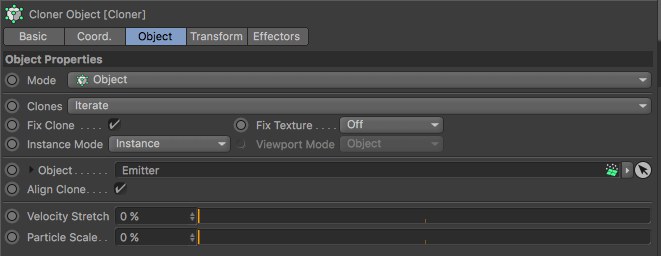
Objects such as those listed in the image above can be placed into this field. The object that defines the shaping must be made a child of the Cloner. The settings that will subsequently be made available will correspond to the shape used. These settings are described below.
 Head model: © Bunk Timmer
Activating this option will fix the Cloner’s X axis in the direction of the surface, point or edge Normals. The Up Vector option, described below, can be used to influence the remaining clones’ rotations.
When this option is activated, the Cloner’s axis will be aligned to the axis of the object on which it grows.
If a polygonal object is used in conjunction with a cloner, the clones will be arranged onto its vertices, edges, polygons, surfaces or selections. Either polygonal or parametric primitives can be used. Of course Subdivision Surfaces can also be used. By nature, many vertices will be created, thus really bogging down your computer due to the immense number of clones that will be generated.
Activating the Align Clone option clearly aligns a clone’s Z axis but not the rotation around it. Picture a surface, deformed using a (see Displace Object) and an animated noise, on whose vertices clones have been arranged. When viewing the animation you will see that the Z axis point in the direction of the corresponding surface Normals but the rotation around this axis takes place in a more or less random fashion. If an up vector is now set (using the coordinate system of the object on which the clones grow) this random rotation will be halted. Basically, this works in the same fashion as the, Align expression (Cinema 4D Tags), the only difference being that a ready-made vector has to be selected instead of a target object being defined.
As an alternative, a Target Effector can also be used. The result will be similar.
 Modes from top to bottom: Point; Edge; Polygon Center; Surface; Volume.
Use this setting to define where the clones should be arranged:
- Vertex: A clone on each vertex point.
- Edge: A clone on each edge (additional settings will be made available).
- Polygon Center: A clone on each polygon center.
- Surface: Clones randomly arranged over an object’s entire surface.
- Volume: Randomly dispersed Clones within an object’s volume.
Edge mode offers the following options:
- Offset: Moves the clones along the edge (values less than 0% or greater than 100% can also be define, whereby the movement of the clones will not be limited to the edges).
- Scale on Edge: The clones will be scaled in the direction of the edge.
- Edge Scale: Use this slider to adjust the size of the clones in the direction of the edge (only available if Align Clone and Scale on Edge are active). Note that values greater than 100% can be entered.
- Volume mode
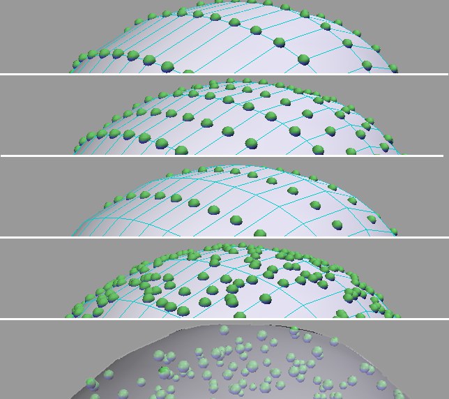
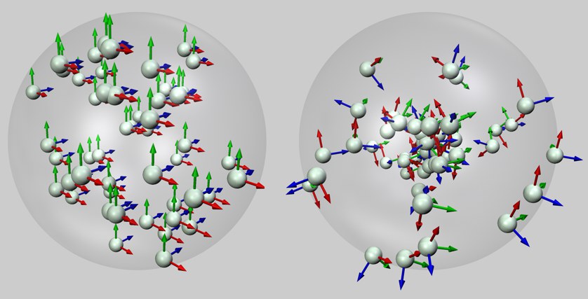 Random mode at left, Surface mode at right, each within a sphere’s volume.
Use this option to define how the Clones should be dispersed within the given volume. Applying the Random option will disperse the Clones randomly within the given volume. Applying the Surface mode will initially disperse the Clones over the object’s surface and orient their Z axis in the direction of the surface Normals. Subsequently the Clones are pushed to various depths towards the center of the object’s volume, in the opposite direction of the surface Normals. As you can see in the example above, the Z axis (blue) of each object points in the direction of its initial surface position.
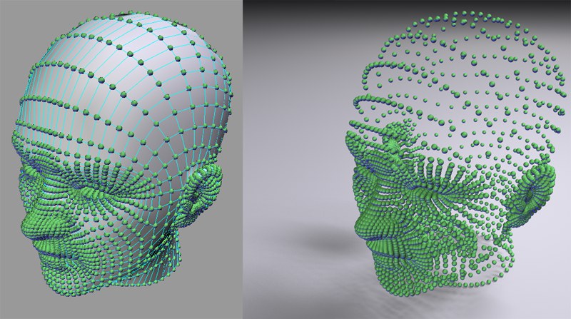
The Surface mode should be used if you want to fill more complex volumes with Clones since the volume’s contour as a whole will be more accurately reflected:
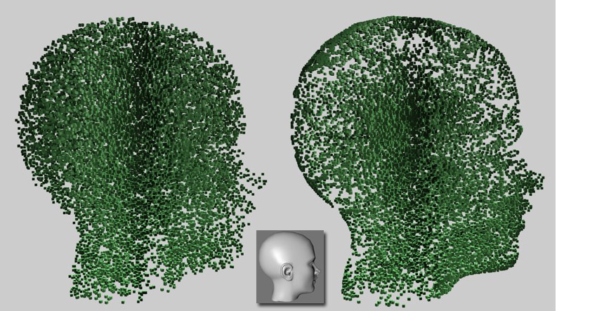 Head model: © Bunk Timmer. At left: Random mode; at right: Surface mode.
If you don’t want the Clones to rotate when Surface mod is used, apply a Target Effector with a very distant target and, if necessary, define an Up Vector.
Not all objects that can be dragged into the Object field function with the above modes (e.g., the Text Object). In such instances it often helps to make the element a Child of a Connect Object, which is in turn made part of the clone process.
Selecting Surface will make the Seed and Count settings (Seed: Different values will result in different random arrangements; Count: Number of clones that will be randomly arranged onto the object’s surface). If this mode is selected when working with a selection, the clones that lie outside of the selection will be hidden. For example, if a specific number of clones to be arranged onto a given surface have been defined (e.g., 473), only those clones on the selection will be displayed (e.g., 34).
Any vertex-, edge-, or polygon selection made using the Selection tag can be placed into this field. Only the clones arranged in the area of that selection will be visible.
Use this setting to enable or disable cloning on a given Selection tag.
Use this setting to restrict the clones to a currently active selection.
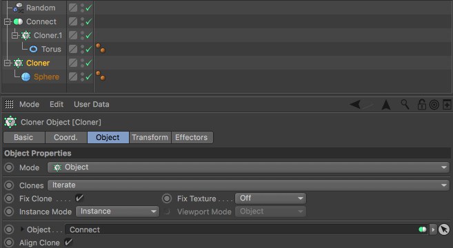
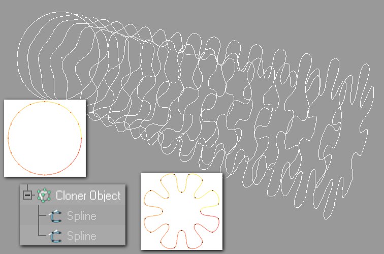
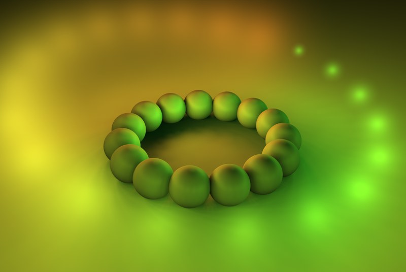
If a Cloner Object is made a Child Object of a Connect Object (main menu: Create / Modeling), all Clones will be viewed as a single object. In this case a new Cloner Object can be used to create clones on the surface of this single object.
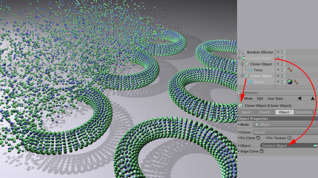
So, what’s taking place in the scene above? The top Cloner Object (in Grid mode) has cloned a ring several times in a grid array. The Cloner Object was then made a Child Object of a Connect Object which, in turn, causes all rings to be viewed (internally) as a single object. This makes it possible for the bottom Cloner Object (in Object mode) to arrange spheres onto the surfaces of the rings, i.e., on the clones as a whole. Additionally, the Random Effector (Falloff tab: Linear) was used to create a random dispersion of the clones.
Sometimes it’s necessary to scale clones depending on the underlying polygons:
 Left disabled, right enabled Enable Scale option.
This works in the Distribution Vertex, Polygon Center and Surface modes. In Vertex mode, all polygon sizes belonging to a given vertex will be ascertained and the clones scaled accordingly. The Scale setting can be used to adjust the clones’ size.
The best results can be achieved if the object to be cloned is about the same size as the average polygon size. Only then will a proportional, foreseeable scaling across polygon surfaces be possible if Scale is set to 100 with a linear scaling spline. A Scale value of approx. 100% will then deliver good results. If the value is set to 0%, the clones will not be scaled. As the value is increased, clones on large polygons will become correspondingly larger and clones on small polygons will become correspondingly smaller.
If a value of less than 0% is used, the effect will be inverted.
Note that when the Activate Scale option is enabled, the average polygon surface will be calculated, saved and used as a basis for individual clone sizes. If you want to subsequently change the polygon size and disable Activate Scale and then enable it again, all clone sizes will change based on the modfied average polygon surface.
This setting can be opened by clicking on the small triangle to the left of the Enable Scaling option. This graph can be used to precisely adjust the scaling in relation to the polygon size. The X-axis represents the polygon size and the Y-axis the scale size.
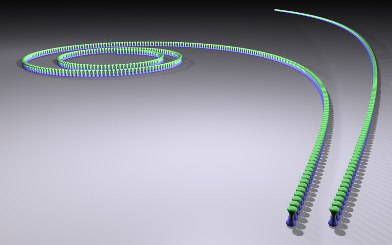
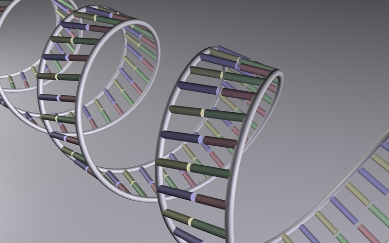 A simplified DNA strand created using two helix splines. Clones were used to create the base pairs.
If the Cloner is used in conjunction with a spline (spline primitives will work as well), the clones will be arranged onto the spline. The type of spline used does not play a role (the Cloner offers settings that can be used to arrange clones uniformly).
The Spline Effector can also be used to, among other things, evenly transform any arrangement of clones onto a spline.
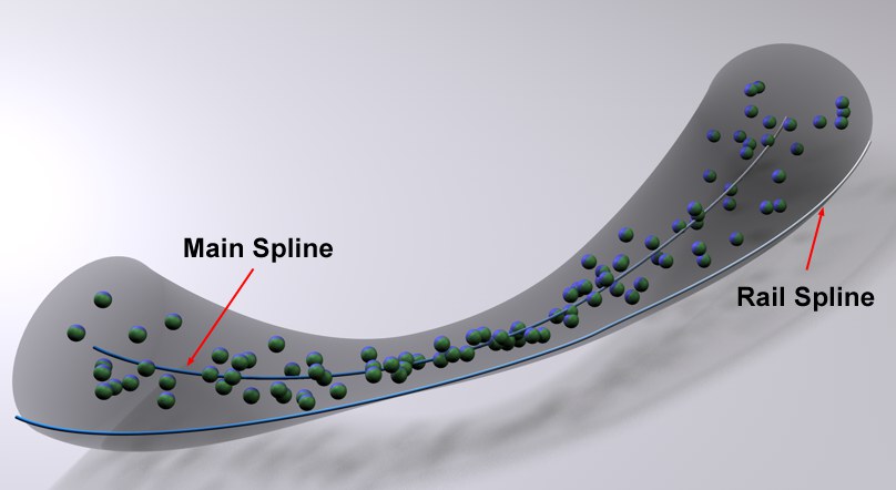
Activating this setting will make the clones follow the shape of the spline tangentially with their Z axis. Otherwise the Clones’ orientation will be aligned in accordance with the World Coordinate System.
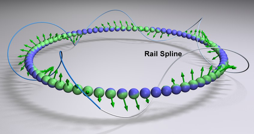 The Clones will orient themselves to the Rail Spline. Target is disabled.
A Spline can be dragged and dropped into this field. The Clones will then orient themselves to a certain point on the Spline along their Y axis (if the Target option is enabled - otherwise as accurately as possible). The point to which the Clones will be oriented depends on the position of the Clone along the Spline to which it is aligned. Clones positioned at the beginning or end of the Spline will orient themselves in the direction of that respective end. Clones positioned in-between will orient themselves in accordance with their distance from the end to which they lie closest.
Make sure the main Spline’s subdivision is high enough. For straight Splines consisting of only two points it may be necessary to set Intermediate Points to
Disable this option to allow the Clones to arrange themselves freely on the Rail Spline. Otherwise their Z axis will be bound tangentially to the main Spline.
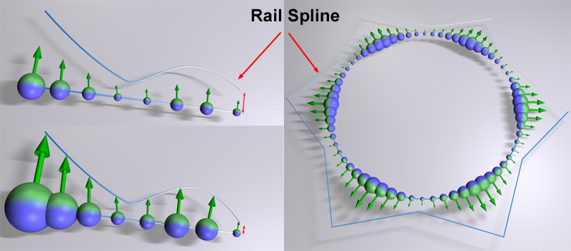 Various Scale effects. At left Spline points with varied intervals were used, which affects the Clones’ size accordingly.
Enable this option if the Rail Spline should also influence the size of the Clones.
The variable spline point intervals will be used to scale the Clones. Make sure the first points of the primary and Rail Splines, respectively, lie relatively close together. The distance between these points defines the general scaling of the Clones. If the distance is approximately equal to the size of the Clones, this will define the size of the other Clones fairly accurately.
The first Clone is always the same size of the cloned object.
When in this mode, a Cloner’s children will be assigned to other objects. There are two methods that can be used to tell the Cloner on which object clones should be generated:
- Make the Cloner Object a child of the shaping object.
- Place the shaping object into the Object text field.
If both of the above-mentioned conditions are true, #2 will receive priority.
The clones will be assigned as follows:
- Polygonal objects: Vertices, edges, polygon center, randomly arranged onto an object’s surface, selections.
- Splines: Along the splines.
- Particle emitters or Thinking Particles particle groups: Onto the particles.
- Matrix Objects: A clone will be positioned onto each vertex of the matrix.
A Cloner will also function if it is itself a child of a polygon object, spline or emitter. In the case of the emitter, the Object text field should not contain any object. Even Cloner Objects within a hierarchy can be cloned, e.g., if the hierarchy below is used:
When in this mode, a clone’s child objects will be arranged linearly (can also be curved), originating from the Cloner. The clone’s Position, Rotation and Scale settings can be modified which will cause the child objects to move accordingly.
Selecting this mode will arrange a clone’s child objects circularly around the center of the Cloner.
Selecting this mode will arrange a Cloner’s child objects in a grid-like manner. This can be used to achieve effects such as the one below:
The object (insert) was cloned and its rotation varied in the Grid Array mode.Some very nice effects can be achieved by letting an Effector fly through such an arrangement of clones.
Since using Grid Array can generate very many objects, thus slowing the editor view, the following Cinema 4D level of detail settings can be used:
- Editor view: Display / Level of Detail
- Display tag. Assign the tag to the Cloner.
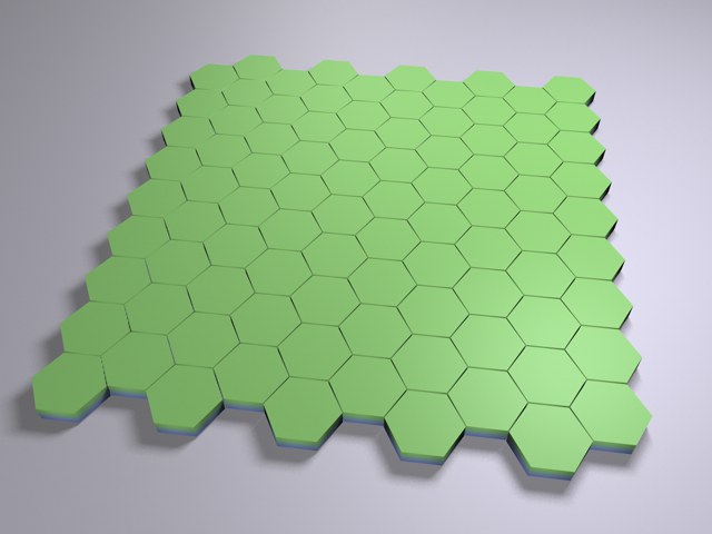
This mode creates a simple grid in which every other row is offset horizontally so individual clones are positioned at the center of the clone lying above it. A honeycomb pattern will be created, which can, for example, be used to create brick walls or similar patterns.
Use this setting to define how the clones will be spaced on the spline:
- Count: Use the neighboring Count setting to define the number of clone segments. Clone spacing will not be uniform, but dependent upon the spline interpolation (i.e. Natural, Even or Adaptive). This result is more often not desired and can be countered by the following modes.
- Step: Use the neighboring Step setting to define the interval between clones along the spline. The spline will be covered in its entirety by clones.
- Even: Use the neighboring Count setting to define a number of clones. The clones will be arranged with equal intervals along the spline.
- Spline point: A Clone will be arranged on each Spline point. No parameters for modification will be available.
- Group 1,2,3,4: If cloning is applied to a MoSpline, these for options will be made available. More information can be found in the L Systems section.
 At top: Per Segment not active. At bottom: Per Segment active.
Activate or deactivate this setting depending on whether the defined number of clones or steps should be applied to a spline as a whole or per spline segment (each segment will then be viewed as an individual spline).
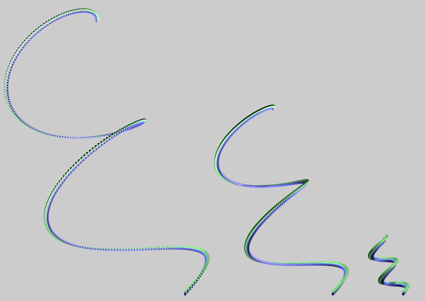
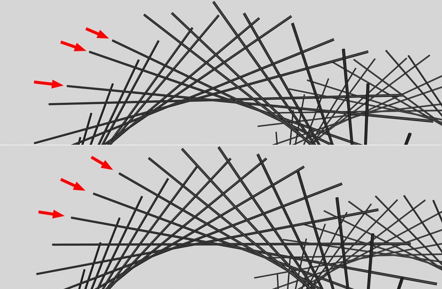 At top: Smooth Rotation not active. At bottom: Smooth Rotation active. Long cylinders were cloned along a helix-shaped spline).
If irregular results occur, as in the top half of the above image, this setting should be activated in order to achieve a more exact calculation of angles for all clones. Irregular results very often occur when splines with few defined vertices are used. Nevertheless, activating this option can also lead to unwanted results:
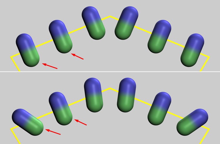 Top: Smooth Rotation not active. Bottom: Smooth Rotation active.
Both marked clones are located on a straight spline segment. If Smooth Rotation is active, the clones will be rotated smoothly, thus preventing a tangential orientation (which can occur if Smooth Rotation is not active).
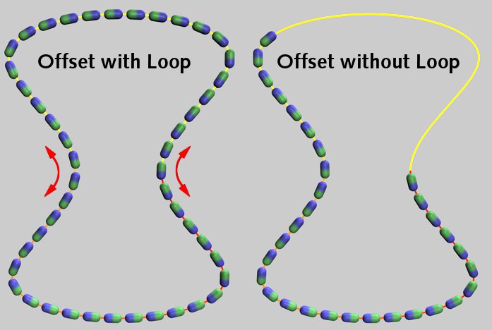
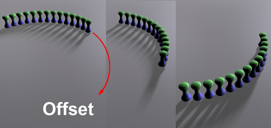
A spline always has a beginning (yellow in point mode) and an end (red). If Offset is set to 0%, clones will be arranged from the beginning to the end of the spline. If the Offset value is raised, the first clone (as well as all subsequent clones) will be arranged further along the spline, in accordance to the value entered. If Loop is also active, all clones will be arranged along the spline in a complete loop. If Loop is not active, the clones that are arranged past the end of the spline will be deleted. Setting the Rate slider to a value not equal to 0% will cause the clones to circle in the course of an animation (setting keys for Offset will not be necessary).
Use this setting to vary the otherwise equal intervals between clones.
Use these settings to limit or expand the arrangement of clones along the spline.
If Offset and Rate are set to values not equal to 0%, clones arranged past the end of the spline will be deleted (Loop not active) or seamlessly (without transition) reinserted at the beginning of the spline (Loop active).
Loop should always be activated if the clones should circle endlessly on the spline.
Rate basically functions like Offset, with the exception that the clones will move automatically when the animation is played, without having to set keys. This setting defines the distance the clones should travel per frame of animation. Activate Smooth Rotation if any irregular movement should occur.
Use this slider to randomly vary the clones’ velocity. If the value defined is high enough, individual clones can even be made to move in reverse. Values less than 0% and greater than 100% can also be defined.
This setting influences the random dispersion of velocity of the clones. Vary this value to randomly vary the clones’ velocity.
 The Volume Spread can be used to arrange Clones to a tubular-shaped cluster.
If a Rail Spline is used, it can be made to define a volume within which the Clones will be dispersed. The distance between Spline points will be used as a reference that defines the radius of the primary Spline, within which the Clones will be dispersed when Volume Spread is set to 100%. A value of 0% will cause the Clones to lie exactly on the main Spline.
This is basically the easiest method with which a cluster of objects can be made to roughly follow the shape of a Spline without using Particles (set Velocity to greater than 0). For example, blood cells flowing through a vein can be animated using this method.
If a Cloner is used in conjunction with a Cinema 4D emitter, a clone will be created for each particle. This, combined with the numerous available Effectors, offers possibilities above and beyond what the Cinema 4D particle system by itself can offer
If this setting is active, the clone’s Z axis will be aligned with the particle velocity vector, which will result in a tangential behavior along the particle path. The Emitter’s Tangential setting must also be activated.
Use this slider to stretch the clones in the direction of the velocity vector. The clones will be stretched proportional to the particle speed. The greater the particle speed, the more the clones will be stretched, independent of the value entered for Velocity Stretch.
The Emitter’s End Scale setting can be used to generate uniform particle growth. This slider merely multiplies this Emitter setting.
Particles (Thinking Particles)

Thinking Particles can also be used in conjunction with MoGraph. Simply drag the desired Thinking Particles group from the Thinking Particles Settings (Simulate / Thinking Particles / TP Settings) into the Object field. Clones will then be created for the particles.
If this setting is active, sub-groups (in the order they are arranged in the Thinking Particles Settings) of the particle group placed into the Object field will also be included.
Two types of behavior are available:
- Standard TP: Reflects the normal behavior of Thinking Particles, with the exception that the clone size can be varied via the Particle Scale slider. The Particle Scale slider multiplies the value defined for the Size setting, for example for the P Storm node
- Stretch TP: When in this mode, clones can be scaled along the velocity vector using the Velocity Stretch slider. Clone size can be defined using the Particle Scale slider. Particle Scale multiplies the value defined for the Size setting, for example for the P Storm node.
When in this mode, a clone’s child objects will be arranged linearly (can also be curved), originating from the Cloner. The clone’s Position, Rotation and Scale settings can be modified which will cause the child objects to move accordingly.
Use this setting to define in which order a clone’s child objects should be cloned. The following options are available:
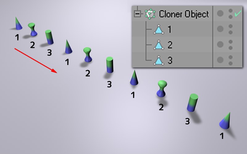
A clone’s child objects will be cloned in the order they are arranged in the Object Manager, from top to bottom.
A clone’s child objects will be arranged randomly when cloned. The random arrangement can be varied by modifying the neighboring Seed value.
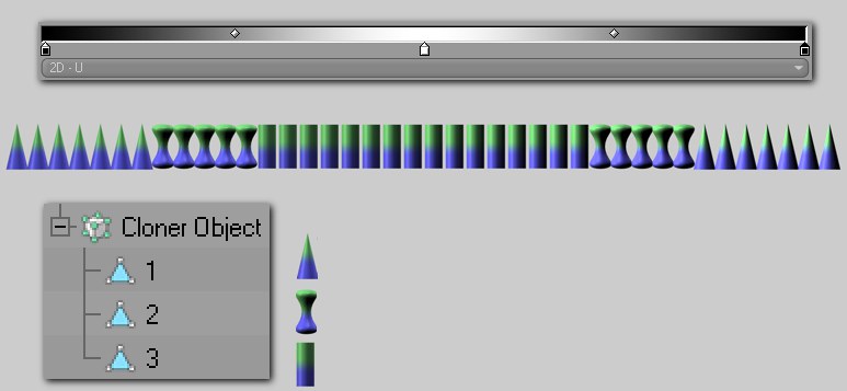
This mode has two functions: First, it can blend parametric primitives with differing settings, as shown below:
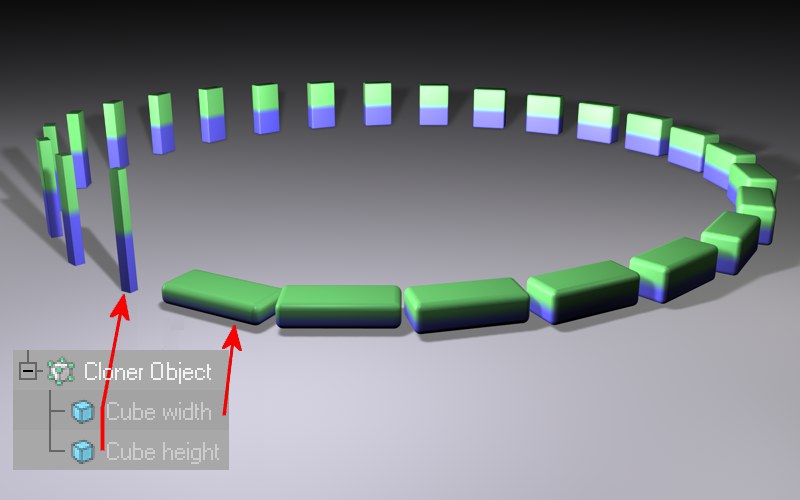
In the image above, two parametric cubes were cloned, each of which have differing Scale and Fillet Radius settings. The Blend ensures a correct interpolation of the object settings. The blend mode can also be applied to more than two child objects at once, whereby the interpolation of the settings will take place in the order they appear in the Object Manager. The parametric primitives must all be of the same type (otherwise no parametric interpolation will result!). Settings or options not able to be interpolated cannot be modified smoothly, but will abrupt.
You can also use this option to blend between polygonal objects containing an equal number of points (Structure Manager).
The Blend mode can also be used to blend spline shapes. The best results can be achieved if both splines have approximately the same number of vertices.
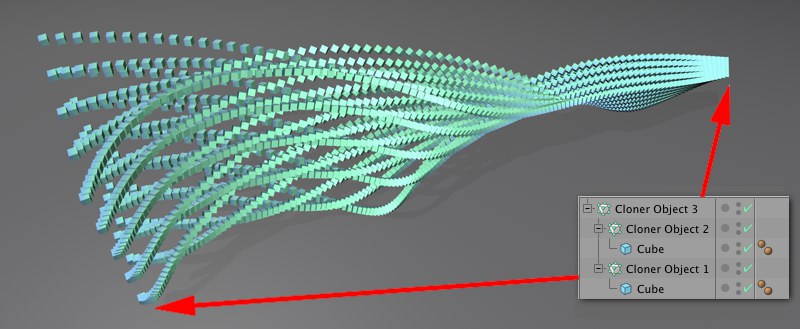
Lights, including their colors and many other settings, can also be cloned, the results of which can be very interesting:
 In this example, color, shadow density and the diameter of the visible light were blended.
Two Cloners (each in Grid clone mode) were made children of a third in Linear mode (Clone set to Blend; Reset Coordinates not active, P.X, P.Y and P.Z =0).
 The Blend setting can be used to blend different Cloners.
Those remaining can then of course be affected by Effectors (whose Modify Clone setting must be increased). More interesting effects will result in conjunction with animated Alembic files, for example, if you blend between 2 Alembic instances with different Offset values. Imagine an animated, cloned character (e.g., fans on bleachers) that possesses all animation states (e.g., a Ransom field in an Effector) and they don’t move in synchronized motion.
The Sort mode first flexes its muscle when used in conjunction with Effectors (those that support this mode must have their Parameter tab’s Modify Clone value set to greater than 0%). The respective Effector can then vary position, scale, rotation, etc. as well as the sequence of child objects used to affect the Cloner. If no Effector were applied, only the first child would be cloned.
A Shader Effector was used in the previous image. The child objects are analyzed in the sequence they are arranged and affect the cloning process accordingly (black=first object; white=last object).
If this setting is not active, differences in position, scale and rotation between the Cloner and the objects to be cloned will be made apparent by the fact that the clones will also be rotated, scaled or moved.
If this setting is active, the first clone will assume the position, scaling and rotation of the Cloner (for you XPresso lovers out there: its matrix will be assumed).
 At top are the three objects to be cloned, each at a slightly different location. Center: Reset Coordinates not active. Bottom: Fix Clone active.
If this option is not active, position, scale and rotation values of animated objects to be cloned will be assumed for the clones.
 An arrangement of clones with a texture applied as a surface projection. Left: No Effector. Center and right: Random Effector with Fix Texture and Fix Texture, respectively.
If a Cloner is textured, the Straight mode will define if the texture should be projected onto the arrangement of clones not affected by the Effectors, thus fixing it on the clones. If the clones are then moved or rotated via an Effector, the texture will move with it. When in Off mode the clones will basically move through the texture and will be affected by the texture according to their location.
This method works with every projection type, except for UVW, camera and frontal mapping.
The Alternate X and Alternate Y modes do the following:
When applied, the projection of all Material tags, except for the initial tag, that lie on a Cloner Object will be reversed in the X or Y direction, respectively. So, what is this good for?
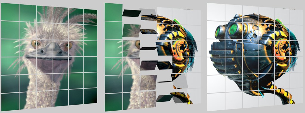 Unreversed projected textures. Images are Copyright Peter Hoffmann (robot) and Fredi Voss (ostrich).
Let’s say you have projected two textures onto a group of Clones. An Effector should fold the Clones over and a non-mirrored image (exactly the same as the texture) should appear on the reverse side. This is exactly the effect you can achieve using the Alternate X and Alternate Y options. The Cloner Object must contain two Material tags, one with Front Side and the other on the Back (assuming the Clones are simple polygons with no volume).
The Material tag’s projection type must be Cubic and the texture must be projected in the Z-direction.
If you have problems using this functionality, an alternative is to use the Stick Texture tag (Alternate X and Alternate Y can then be ignored) after having applied two Material tags with Flat projection to the Cloner Object (one Front and one Back (Side parameter)).
Enter the number of clones to be created here. Each clone will be moved, rotated or scaled by a certain value relative to the previous clone in accordance with the values entered for P.X., P.Y, P.Z, R.X, R.Y, R.Z, S.H, S.P or S.B.
Offset will move the first clone, in accordance with the value entered, in the direction of subsequent clones, thus offsetting the entire line of clones. The function graph can also be used to define how Offset will be applied along the length of the line of clones.
Use this mode to define if the Position, Rotation and Scale settings should apply per step (Per Step) or end point (End Point: the values will be interpolated between the start and end points). You can switch modes at any time.
The Step Effector has a similar function. The Step Effector also offers you a spline graph which can be used to define how the modified settings should be applied along the length of the clone.
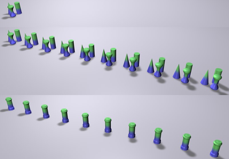
An increasing Amount value from left to right. Only the position of each clone changes (scale and rotation can also be modified).
This slider affects the actual effectiveness of the nine clone settings below it (position, scale, rotation), starting at 0. Mathematically seen, Amount is merely a multiplying factor that affects these nine settings. This setting can be used to create good-looking growth effects.
Use these settings to define if and how clones should be modified relative to the next clone’s position, scale or rotation.
If Per Step is selected, the values will reflect the difference to the previous or next clone. If Endpoint is selected, the values will reflect the difference between the first and last clone, and the values in-between will be interpolated. The position of the last clone can be modified interactively by dragging the orange handle in the editor view (as long as the Step settings have not been modified).
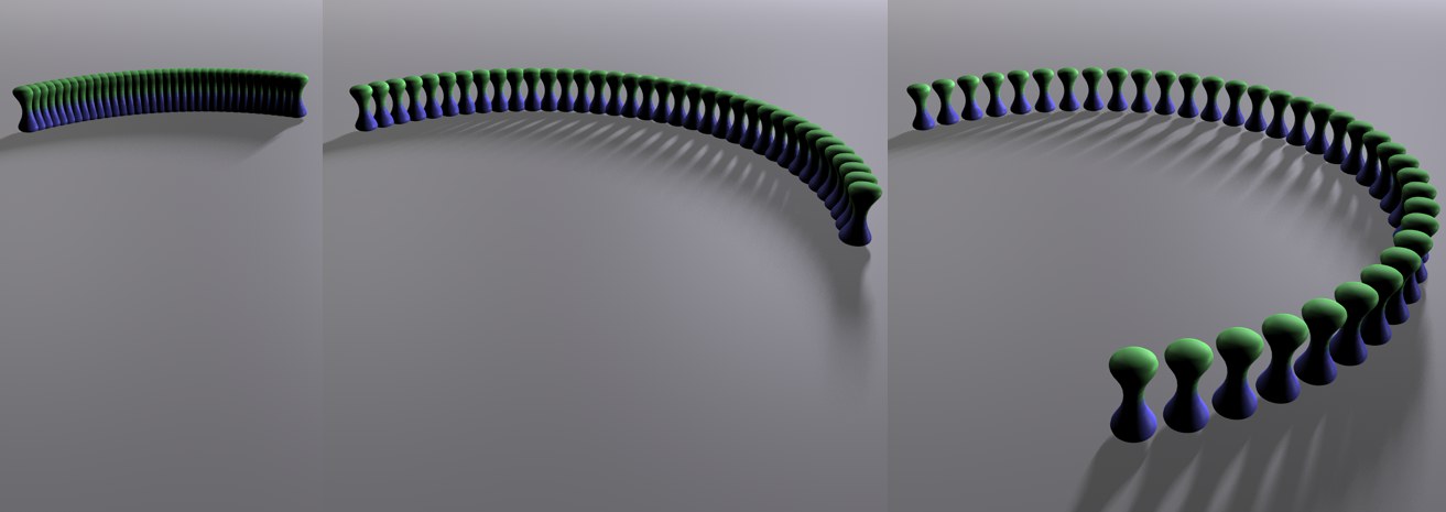
The Linear mode can also be used to arrange clones along a curve or spiral, not just in a straight line, as the name may suggest. This can be done using the following settings:
 From left to right: Cumulative and Single Value modes, respectively.
Use Step Mode to define if the change in rotation should steadily increase from clone to clone (Single Value) or between the first clone and the last clone, starting at 0 (Cumulative). The latter results in spiral-like clone arrangements.
 From left to right: Decreasing Step Size value (the spiral shape was a result of entering rotation values for all three Rotation settings).
Use this setting to define the step interval between individual clones. This is paramount to scaling the entire arrangement of clones (not only the clones themselves!), starting from the origin of the Cloner.
Step Size can also be used to animate a telescope extending (the Amount setting cannot be used to achieve this effect since it would simultaneously increase the cylinder diameter).
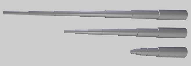 Telescoped cylinders with varied Step Size values in Per Step mode.
Use these three fields to define the curvature of the clone line. If all values are set to 0°, no curvature will occur. Raising these values will increase the curvature accordingly.
Modifying at least two of these values will result in the spline being spiraled; modifying only one of these values will cause the spline to bend in the direction of the respective value (H=Y axis; P=X axis; B=Z axis).
Selecting this mode will arrange a clone’s child objects circularly around the center of the Cloner.
Clones / Reset Coordinates / Fix Texture
These settings work exactly as described for the Linear setting.
Use this setting to define the number of clones to be arranged onto the radius.
This is the radius onto which the clones will be arranged around the Cloner. The radius can also be edited interactively, simply by dragging the orange handles in the editor view.
Use this setting to define the axis plane on which the circle and clones should lie, whereby the Cloner’s coordinate system remains the deciding factor.
If this setting is active, each clone will be arranged with its X axis tangential to the circle. If this setting is not active, each clone will orient itself in accordance with the Cloner’s coordinate system.
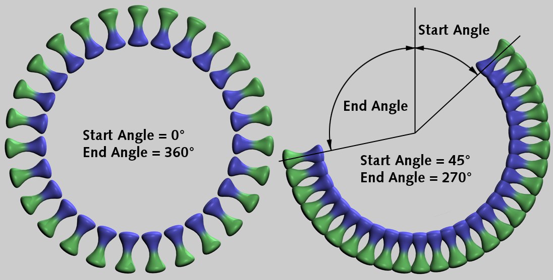
Use these settings to define onto which part of the circle the clones should be arranged. Values less than 0% and greater than 100% can also be defined (this will result in overlapping).
Use this setting to let the clones move along the circle.
Use this setting to randomize the arrangement of clones for a more coincidental look.
Selecting this mode will arrange a Cloner’s child objects in a grid-like manner. This can be used to achieve effects such as the one below:
The object (insert) was cloned and its rotation varied in the Grid Array mode.Some very nice effects can be achieved by letting an Effector fly through such an arrangement of clones.
Since using Grid Array can generate very many objects, thus slowing the editor view, the following Cinema 4D level of detail settings can be used:
- Editor view: Display / Level of Detail
- Display tag. Assign the tag to the Cloner.
Clones / Reset Coordinates / Fix Texture
These settings work exactly as described for the Linear setting.
Use this setting to define the number of clones to be arranged in the X-, Y-, and Z-directions.
You can select from the following methods:
- Per Step: the underlying Scale settings use the clone intervals as a reference (two new handles will be made available at the corners of the Cloner object; these can be used to fine-tune the clones if their intervals are constant and the clone count changes).
- Endpoint: the underlying Scale settings use the entire clone conglomeration’s scale as a reference (the typical Cinema 4D behavior; the handles on the corners of the Cloner object can also be used here: use them to adjust the scale of the cluster as the intervals change).
If the mode is switched, the values will be converted automatically.
Use this setting to define the scale (expansiveness) of the entire arrangement of clones in the X-, Y-, and Z-directions. The orange handles can also be used to resize the arrangement of clones interactively.
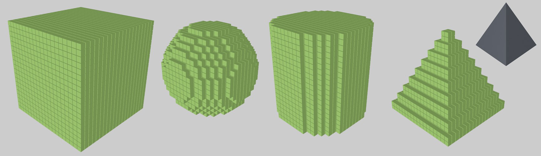 The different shapes; on the right, a sphere was used for shaping
There are the following types of forms from which to choose: Cube, Sphere, Cylinder or any Object shape. As you can see in the example above, with Cylinder, Sphere or object superfluous clones that don’t fit into the shape will simply be ignored.
Lowering this value will reduce the number of clones on the inside of a defined shape accordingly – even to the point where the shape is made hollow (only its outer shell will remain).
Drag any polygonal object into this field (can also be a Generator) within whose volume clones should be generated (this is a faster method than, for example, using the Volume Effector, which works in a similar fashion).
Note that problems can occur if rows come to rest exactly on top of an object’s surface because these might not be seen as being part of the volume. In such a case, the object should be scaled slightly.
In this mode, a flat grid array (see also Wabenanordnung) will be generated in which every other row is offset equally.
In the Viewport you will find interactive handles with which you can adjust the honeycomb array along a single axis (center handle) or along both axes (corner handles).
Use this setting to define the object coordinate axis to which the honeycomb array should be perpendicular. The axis in parethesis define the plane on which the honeycomb array lies.
Use this setting to define how the honeycomb array should be generated: Height will offset every other vertical row, Width will offset every other horizontal row.
This setting can be used to adjust the offset of every other row: a value of 0% will have not effect, 50% will position the rows exactly in the center of the neighboring rows and a value of 100% will create an offset equal to one clone position.
The values defined here represent a maximum value, which can be varied randomly per offset row using the Offset Variation setting.
Use this setting to randomly vary the offset of each row in addition to the other honeycomb dimensions (in relation to the Offset Direction value).
As always, this setting is available when defining random dispersion to create additionsl randomness (see also Seed).
Use these settings to define the width and height of the clone array. The array’s expanse or density will change depending on the Mode defined (whereby the intervals of the honeycomb structure will remain constant). Note that, for rectangular shapes, the total number of clones does not represent the product of both settings shapes but more precisely half. This is because the the value defined for Offset Direction applies to a double row pushed together.
This mode defines whether the following Size Width / Size Height settings should define the honeycomb array (Endpoint) or the clones’ intervals (Per Step). These values will be converted automatically if the mode is switched and the honeycomb array will not be modified. The handles at the corners will change depending on the mode selected - Count Width or Count Height.
Use these settings to define the honeycomb array’s width and height. The clone count will remain constant.
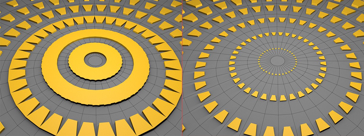
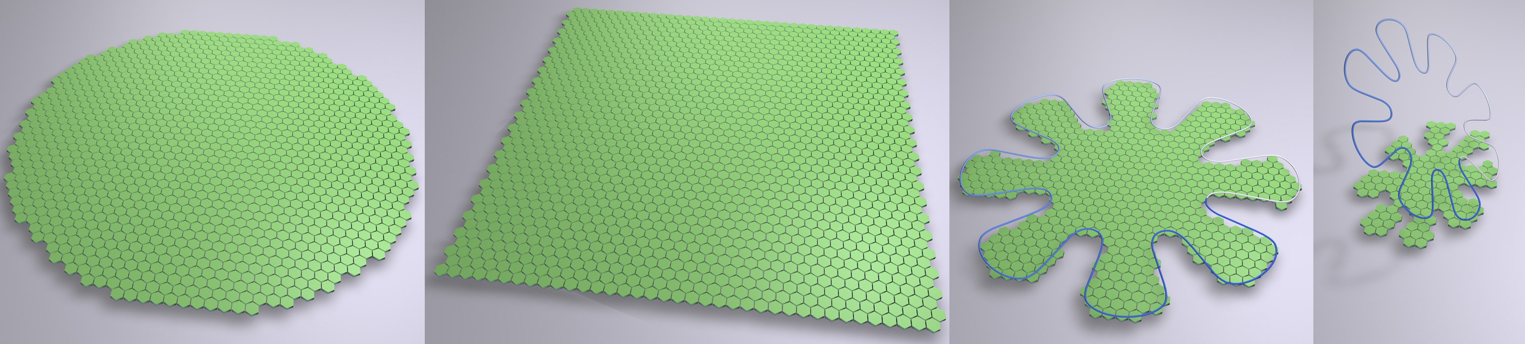 Various Form types.
Since a square honeyomb array is not always desired, this setting can be used to define a specific shape for the array. Square and Circle need no further explanation. The Spline setting can be used to create a custom shape.
Drag a spline into this field that lies perpendicular to the honeycomb array, which will then be projected onto the array (at right in above image). Only those clones that lie within the spline projection will be generated. Open splines will be closed internally.
When in this mode, a Cloner’s children will be assigned to other objects. There are two methods that can be used to tell the Cloner on which object clones should be generated:
- Make the Cloner Object a child of the shaping object.
- Place the shaping object into the Object text field.
If both of the above-mentioned conditions are true, #2 will receive priority.
The clones will be assigned as follows:
- Polygonal objects: Vertices, edges, polygon center, randomly arranged onto an object’s surface, selections.
- Splines: Along the splines.
- Particle emitters or Thinking Particles particle groups: Onto the particles.
- Matrix Objects: A clone will be positioned onto each vertex of the matrix.
A Cloner will also function if it is itself a child of a polygon object, spline or emitter. In the case of the emitter, the Object text field should not contain any object. Even Cloner Objects within a hierarchy can be cloned, e.g., if the hierarchy below is used:
When in this mode, a clone’s child objects will be arranged linearly (can also be curved), originating from the Cloner. The clone’s Position, Rotation and Scale settings can be modified which will cause the child objects to move accordingly.
Selecting this mode will arrange a clone’s child objects circularly around the center of the Cloner.
Selecting this mode will arrange a Cloner’s child objects in a grid-like manner. This can be used to achieve effects such as the one below:
The object (insert) was cloned and its rotation varied in the Grid Array mode.Some very nice effects can be achieved by letting an Effector fly through such an arrangement of clones.
Since using Grid Array can generate very many objects, thus slowing the editor view, the following Cinema 4D level of detail settings can be used:
- Editor view: Display / Level of Detail
- Display tag. Assign the tag to the Cloner.
This mode creates a simple grid in which every other row is offset horizontally so individual clones are positioned at the center of the clone lying above it. A honeycomb pattern will be created, which can, for example, be used to create brick walls or similar patterns.
Clones / Fix Clone / Fix Texture
These options function the same as those described under Linear mode.
Use the Scale setting to define X, Y and Z expansion of the entire grid of clones in the. This can also be done interactively using the orange handles.
You can select from three shapes: Cube, cylindrical or spherical.