Shaping
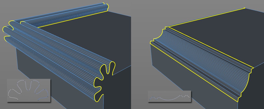
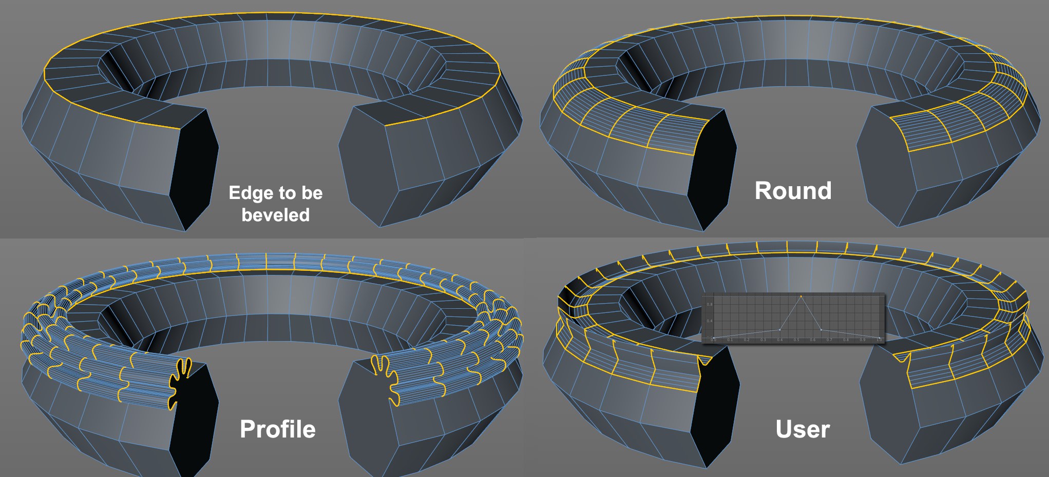 Shape modes: Profile with the pictured spline, User with the pictured function graph (and disabled Symmetry option).
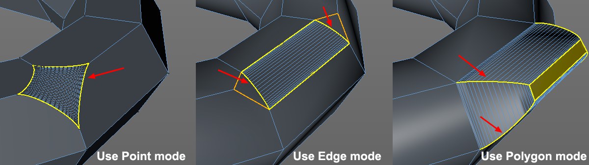
The flattened or dissolved edges can be given any new shape (e.g., if you bevel a cube’s edge and view it from the side you will see the new shape). Use the Shape setting to define this shape. Note that the following examples were all created in Use Edge mode. The Shape setting can also be used in Use Polygon and Use Point modes on the marked edges:
The edge will always be created as a circular segment - if Tension is set to 100%. Otherwise an elliptical shape will be created.
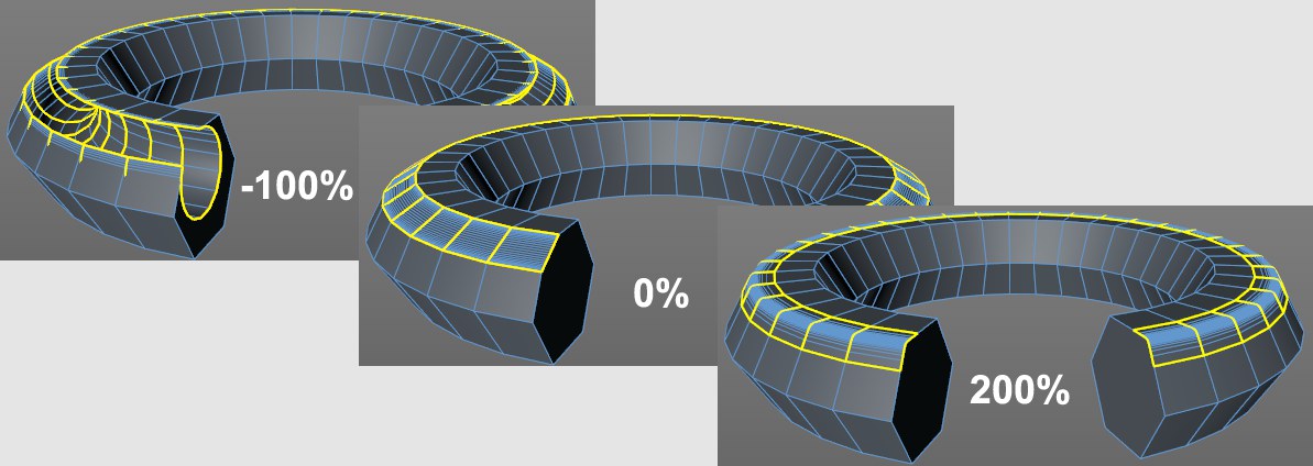 Various Tension values.
Use this setting to adjust the arc’s tangent (direction AND length). At a value of 100%, the arc will run tangentially from both neighboring surfaces. Lower values will cause the arc to move concavely or convexly, depending on the original edge (outer or inner edge). Note also the Depth setting, which can be used to affect the curvature.
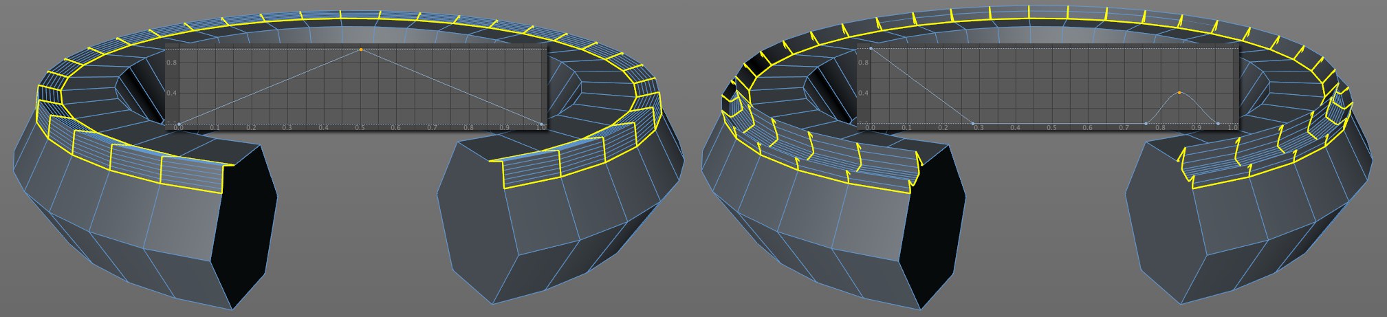 Function graphs make it possible to create precise shapes (Symmetry disabled).
When in this mode, a function graph can be used to shape the original edge. If Symmetry is disabled, the function graph’s shape can be imagined directly between both diverging edges (the Depth setting defines the direction and scale of the curve’s modification). Set Subdivision to a value that will reproduce the curve as accurately as possible.
When in Use Point mode, the User and Profile options only have a limited effect.
If disabled, the function graph will be adapted to to both diverging edges with increasing Offset values. If enabled, the function graph will be duplicated (mirrored at right end).
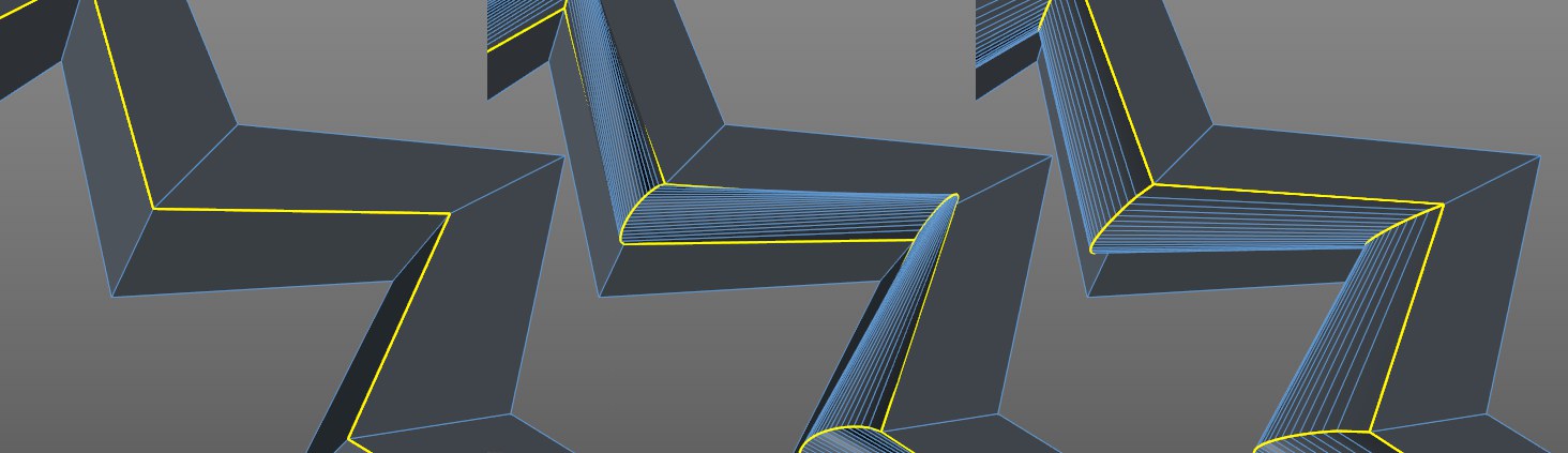 Beveling the edge shown produces the edges shown: At left with Constant Cross Section disabled (center) and enabled (right).
Depending on the edge to be beveled, a tubular effect (with regard to the rounding volume) can result if the User or Profile modes are used. If Constant Cross Section is enabled, this effect will remain more-or-less constant (especially at corners).
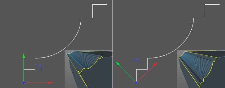
 2 different splines and the resulting edge shapes.
When in this mode you can freely define the shape of a beveled edge. A spline can be used to define the shape of the edge to be dissolved. The subdivision will be defined by the spline (the Bevel tool’s Subdivision setting will have no effect).
Splines used to define an edge’s shape must have the following properties:
- The spline may not be closed
- The plane on which the spline lies must be defined in the Profile Plane setting. For example, if you create the spline in the Front view, the XY plane should be defined.
- The spline’s axis must be correctly defined:
Assuming the Profile Plane is set to XY, the bevel will take place along the object’s X axis and will include a variance in the Y direction in order to create the bevel edge shape. In the image above, you can clearly see why the axis orientation at the left, which is created more-or-less automatically when the spline is modeled, fails. The best method is to set the object axis to the spline’s starting point and rotate it so the spline end point lies on the X axis. This produces decent results because the spline is positioned as an edge between the edges diverged by the Offset setting. The Depth setting must be used to adjust the size of the concave or convex bevel!
Note that problems can occur when beveling 2 or more edges that meet at a given point.
Use this setting to define the plane (object coordinate system!) in which the profile spline lies. This is important for the orientation of the object axis, as described above.