Mesh Menu
The
Any objects that you want to use with these tools must be editable. You can make objects editable by selecting them and choosing Mesh / Conversions.
Usually, the Structure tools affect the selected points, edges or polygons only. However, if none of these elements are selected, then most of the tools will affect the entire selected object(s). Hidden elements will usually be ignored. Some tools such as Knife, Bevel, etc. can be used to "grab" an element (e.g., an edge) directly with no prior selection.
Any structure tools that cannot be used in the current editing mode (point, edge or polygon) will be grayed out. For example, Edge Cut only works with edges and therefore will be grayed out in point mode and in polygon mode.
You can also use the structure tools with multiple selected objects. For example, you could create two cubes, make them editable, select a polygon on each cube and extrude both polygons at the same time using the Extrude tool.
For all tools whose affect on hidden elements can be disabled (e.g., the Knife tool), the Customize Commands Manager offers the Toggle Visible Only command. Assign a hotkey for this command to easily switch between modes.
When using an interactive tool the most recently completed action can be undone by pressing the Esc key on your keyboard as long as the mouse button is still pressed.
The workflow for using the structure tools differs depending on whether you are working in the default modeling mode (Tools / Default Mode) or in the tweak modeling mode (Tools / Tweak Mode).
Note also the Sculpt Brush, which can be used to affect normal polygon meshes (without special Sculpt subdivision).
Working with hotkeys when modeling
A typical workflow is, for example, as follows:
Select several polygons, edit them using the Extrude tool, switch back to the Select tool and select the next set of polygons to edit.
This can be done in one of two ways using hotkeys:
- Select a polygon using the Live Selection tool, press the
D key (hotkey for Extrude tool), click and drag to extrude and then press theSpace bar to switch back to the previous tool. Or: - This also works as follows: Select a polygon using the Live Selection tool, press and hold the
D key, click and drag to extrude and release theD key to return to the Live Selection tool.
You can use most of the structure tools interactively. Also, many of the tools have settings that you can adjust in the Attribute Manager. For as long as the tool is active, you can change any of its parameters or options and you will see the changes applied in real-time.
You can quickly access various commands for points, edges and polygons from the context menu. Different commands are available depending on whether you are working in point, edge or polygon mode These commands are mostly from the

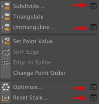
Several commands (mostly in the Mesh menu) have multiple options. It can be irritating if these are displayed every time a given command is called up. This is why the icon as highlighted in the image above is available. When clicked upon, the command options will be displayed and can be defined accordingly. These settings will then apply EVERY time the command is called up.
The Customize Command Manager contains an option that lets you define the previous method (options will be displayed each time a command is called up) or the new method should be applied when a command is called up (via hotkey only).
RELEASE 22
In general there are several minor new modeling features that are not in the form of new features but are improvements in performance. For example:
- The
 Select Connected
 - Minor improvements such as faster Use Edge and Point mode, generating more precise geometry for n-gons, etc.
-
 Spin Edge
 - The
 Collapse
 -
 Bevel
Bevel -
 Slide
Slide -
 Iron
Iron -
 Stitch and Sew
 -
 Move
Move - The
 Extrude
Several of the tools described in this section can also be found in the main menu under Splines. This is because they work for both object types. However, they are only described here.
Hand, head and figure models in the following sections are © Bunk Timmer
Polygon Pen
Parameters
Line Cut
Bevel Tool
Extrude
Extrude Inner
Volume Mesh
Create Point
Close Polygon Hole
Bridge
Matrix Extrude
Smooth Shift
Subdivide
Subdivision Surfaces Weight
Weld
Stitch and Sew
Melt
Collapse
Dissolve
Optimize
Array
Resolve Non-Manifold
Clone
Mirror
Split
Disconnect
Plane Cut
Loop/Path Cut
Edge Cut
Connect (Points/Edges)
Triangulate
Untriangulate
Iron
Brush
Magnet
Set Point Value
Slide Tool
Spin Edge
Change Point Order
Normal Move
Normal Scale
Normal Rotate
Edge To Spline
Make Editable
Current State To Object
Connect Objects
Connect and Delete Objects
Polygon Groups to Objects
N-gon Triangulation
Retriangulate N-gons
Remove N-gons
Align Normals
Reverse Normals
Break Phong Shading
Unbreak Phong Shading
Select Broken Phong Edges
Axis Center
Reset Scale
Spline Boole Commands