The UV Editor and Its Tools - An Introduction
Cinema 4D 2026.3 introduces a completely new UV Editor along with new UV tools. The previous UV Editor and the UV tools familiar from Bodypaint 3D have been completely removed and replaced by these new features. The new UV tools offer seamless integration with modeling options and can often be used exactly as in modeling with points, edges, and polygons.
In addition, the internal handling of UV coordinates has been fundamentally changed. Instead of assigning a separately managed UV coordinate to each polygon vertex, the UV context and coordinate for each vertex are now managed collectively. This makes the detection of contiguous UV structures more robust and enables the use of advanced UV features.
Without delving directly into the intricacies of each available tool, a brief example will illustrate the basic workflow in a practical way. For this, we’ll use a model of a human head that doesn’t yet have any UV coordinates. However, an object with existing UV coordinates could be processed in the same way. But first, let’s get an overview of the UV layout, where all the necessary managers and functions can be found.
Overview of topics:
- What are UVs used for?
- The UVEdit Layout
- Typical Workflows
- Well-known modeling tools that also work in a UV context
What are UVs used for?
Cinema 4D offers various options for defining how a material is assigned to an object (see Material Tag or, for example, the UV Projection Node). For example, a material can be wrapped around an object in a cylindrical, spherical, or cubical shape. However, these projections based on basic geometric shapes do not always produce the desired result, for example, when the material contains textures that are supposed to appear undistorted on specific parts of the object’s surface.
In such cases, you must work with UV coordinates. In this process, each point on an object is assigned additional information specifying which area of the material should be visible there. The object’s three-dimensional shape is thus converted into a two-dimensional unwrap, which can then be adjusted to match the 2D textures in the material.
Another reason to use UV mapping for materials is that this type of projection remains fixed to the surface even when the object is deformed. It is therefore essential for animated characters.
The UVEdit Layout
In the upper-right corner of the Cinema 4D interface, you’ll find the various included layouts, which are optimized for specific workflows, such as Sculpt for organic sculpting, Track for object or camera tracking, or UVEdit to edit UV coordinates. New tools, managers, and functions specific to the selected purpose become visible in the layout—features that are otherwise only accessible via menus. The UVEdit layout is optimized for editing UV coordinates (see the following figure).
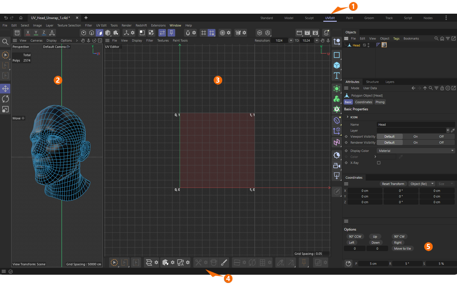 The main components of the UVEdit layout.
Let’s take a quick look at the elements highlighted in the figure above:
-
Switching to the UVEdit layout brings up the UV Editor, where the actual work and display of UV coordinates take place. In addition, various menus, managers, and toolbars are displayed that are specifically designed for working with UV coordinates. Since every change to the UV coordinates is automatically saved in the UVW Tag for the corresponding object, you can switch back to the standard layout at any time without losing the changes made to the UV coordinates.
If UV coordinates are already available for an object, simply select the UVW Tag for that object in the Object Manager to view the UV coordinates stored in that tag in the UV Editor and edit them there. -
The UVEdit layout also features the familiar 3D viewport, allowing you to keep the 3D object in view. Here, you can still select points, edges, or polygons, for example, which can then be used with UV tools. Most of these selection tools, as well as the standard transformation tools (Move, Rotate, Scale), also work in the UV Editor, so you can use the same tools in both the 3D View and the UV Editor. Only the effect is different. Changes to Points, Edges, and Polygons in the 3D view alter the structure and shape of the object, whereas changes in the UV Editor only alter the projection of textures onto the surfaces. The UV Editor thus displays the model from the perspective of an assigned material.
-
Here you will find the UV Editor, which displays the UV unwrap of the currently selected object and its selected UVW Tag. Additional markers indicate the size of the standard UV tile, whose internal coordinates in the U and V directions range from 0 to 1. However, UV coordinates outside this range are also permitted. These are automatically transferred to adjacent UV tiles (keyword: UDIM).
-
This toolbar contains the most important selection methods and UV tools. Alternatively, have a look at the > menu in the top bar, which also contains all UV functions.
-
Below the Attribute Manager, additional options and buttons are available, such as those for rotating UV coordinates in increments or moving them to an adjacent UV tile.
Typical Workflows
Download this zipped project file so you can follow along with the instructions below. This will give you a hands-on understanding of the key workflows involved in creating and editing UV coordinates.
Unwrapping UV Coordinates
Whether the object you're working on already has UV coordinates or doesn't have a UVW Tag at all, the UV Unwrap and Relax tool can handle both cases. In the familiar Edges mode, you can define so-called Seams—that is, lines of intersection along the edges of the geometry—along which the UV coordinates should be separated. This is therefore usually the first step.
To mark Seams, there is a dedicated selection tool that works similarly to edge Path Selection. You can use various modes with this Seam Selection tool, such as selecting entire edge loops directly. Otherwise, the Live Path mode is often helpful; simply hold down the left mouse button and brush along the edges in sequence to select them as Seams. You can also pause, for example, to rotate the perspective view, and then resume selecting the Seam edges by holding down the left mouse button again. If something goes wrong, you can always deselect Seams by holding down Ctrl while doing so.
The following video shows the entire process, from creating a Seam Selection to UV unwrapping, and concludes with the adjustment of the position, size, and orientation of the resulting UV coordinates.
The demonstrated functions and tools are:
-
Seam Selection: Used to mark the edges along which the object should be cut to unfold the UV coordinates.
Please note that selecting Seams automatically adds a special Edge Selection Tag to the object, which provides additional functions such as deleting or selecting the seams (converting a Seams selection to an Edges selection). -
UV Unwrap and Relax: Unwrap the UV coordinates and balance the edge lengths through automatic relaxation so that the proportions of the UV polygons match those of the geometric polygons as closely as possible.
-
Align UV Island: By clicking on an edge in the unfolded UV coordinates, the corresponding UV island can be automatically rotated to match the direction of that edge.
-
Selections within a UV Island: In Polygons mode, double-clicking a UV island automatically selects the entire island. In Edges mode, double-clicking selects an edge loop. Double-clicking in the empty space of the UV Editor deselects everything. In addition, the UV Editor offers many selection methods familiar from modeling. For example, you can use the Rectangle Selection or Brush Selection tools, or the standard Move, Rotate, or Scale tools, which allow you to select individual UV elements by left-clicking on them or multiple elements by holding down the right mouse button.
By holding down the Shift key, you can build even complex selections step by step. To deselect individual elements, hold down the Ctrl key as usual. -
UV Transformations: Selected UV elements can be manipulated using the standard Move, Rotate, and Scale tools. In addition, the Coordinates panel includes buttons for rotating or moving elements in increments, or for entering custom values for the transformation of the UV corrdinates.
Additional, equally useful UV Tools
In many cases, simply using Seams in combination with UV Unwrap and Relax is sufficient to achieve a good UV unwrap. Since UV Unwrap and Relax can also be limited to currently selected polygons, an object can be edited in multiple steps and automatically broken down into separate UV islands. The Disconnect UVs tool also offers another option for splitting a UV unwrap into separate UV islands. Let’s briefly cover this in the following video as well. It demonstrates both the separation of UV areas and the merging of UV islands.
The demonstrated functions and tools are:
-
UV Polygon Selection: Select the UV polygons that are to form a new UV island. You can use the standard selection methods familiar from polygon modeling, such as the transformation tools (Move, Rotate, Scale) or Brush Selection.
-
Execute Disconnect UVs: When you click the gear icon next to Disconnect UVs, this command also displays a dialog box that allows you to set the width of the gap to be created between the original and the separated UV island. The boundary between selected and unselected polygons becomes the cut line. Alternatively, an edge selection can also be used as the cut line.
-
UV Transformation: For example, use the Move tool to move the now independent UV island to its new position.
-
Outline Selection: To connect separate UV islands, an edge selection is required. In our case, we simply want to undo the detachment of the selected polygons, so we need an edge selection that includes both the outer boundary of the small UV island and the edges along the the hole in the main UV island. Since the polygons of the small UV island are still selected, the familiar Outline Selection command from the Select Menu can help us here. Clicking on the edge of the polygon selection in the 3D viewport automatically selects the edges along this boundary, both on the main UV island and on the detached island.
-
UV Weld: When UV Weld is activated and the mouse pointer is placed over the selected edges in the UV Editor, lines and arrows appear to indicate the direction in which the edges will be welded. Therefore, it matters which edge the mouse pointer is placed over. In this respect, this function can also be compared to the Stitch and Sew tool in modeling.
To ensure that not only the selected edges are moved and connected, you should also hold down the Shift key at the same time while clicking on the selected edge. This moves the entire UV island (as shown in the video) instead of just the selected edges.
Local Adjustments
Often, after UV coordinates have been automatically unwrapped, local manual adjustments are still needed—for example, to align the placement of UV coordinates with a texture loaded to the background of the UV Editor (see > in the UV Editor). Various tools are available for this purpose as well, some of which are already familiar from regular modeling. For example, you can use a Soft Selection, which can be combined with the standard transformation tools.
However, it is also possible to lock already correctly positioned areas in place using Pins and then automatically relax the surrounding areas. The following video demonstrates these options using the head model shown above as an example.
The demonstrated functions and tools are:
-
Path Selection and Disconnect UVs: The automatic UV unwrapping caused the UV polygons of the oral cavity to be placed between the lips, distorting them into a ring shape. We therefore correct this by selecting a path along the inner edge of the lips and then cutting out this area. This allows us to place the UV polygons separately within the UV tile.
-
UV Island Selection and UV Transformation: Executing Disconnect UVs has created a new UV island, which can be selected in Polygon Mode by double-clicking on it. Using the standard Move Tool, this area can now be dragged to a new location within the UV tile without altering the surrounding UV areas.
-
Managing Selections: Note that after detaching a UV island, selected elements may appear multiple times within the UV environment. Since the next step involves modifying only the shape of the lips, we deselect the edges at the perimeter of the detached oral cavity. As in the 3D View, you can also use the keyboard shortcut S, for example, to automatically zoom in on the currently selected elements and center them in the UV Editor.
-
Soft Selections: Selections of UV elements can also be combined with soft selections. This means that when selected UV elements are moved, rotated, or scaled, adjacent areas are also affected. The size of the affected area and the decrease in intensity within it can be specified individually in the Soft Selection Tool dialog. We use this effect here on the edges of the lips on the head model by closing them and positioning them at a more natural distance from the nose.
-
Setting Pins: To lock in UV points that have already been correctly placed, you can mark them using the Pins feature. This ensures that these points remain fixed even if, for example, the rest of the UV island is relaxed. The Pins menu also includes commands for unpinning selected UV points or removing all Pins.
By the way: Pins can also be ignored during transformations or when using other UV tools if the Use UV Pins option is turned off (see icon bar above the UV Editor). -
Relaxing UVs: Using the UV Unwrap and Relax function, a selected UV island can also be simply relaxed—for example, to restore a harmonious distribution of all UV polygons after manually moving individual sections. Existing Pins are also taken into account and remain untouched.
Well-known modeling tools that also work in a UV context
-
Selection Tools
- Known selection tools and functions also work in the UV Editor (such as Brush, Rectangle, Lasso, Polygon, Loop, Ring, Outline, Fill or Path Selection)
- In addition, the Seam selection type is being introduced. This is based on selected edges and is stored in a separate Seam Selection Tag on the object. Seams can be used as cut lines, for example, during UV Unwarp and Relax operations. Furthermore, Edge selections and Seam selections can be converted back and forth between each other.
-
Transformation Tools
- Known Move, Rotate and Scale tools from the modeling environment can now also be used in the UV Editor.
- Soft Selections and Modeling Axis are available for selected UV components as well.
- Brush and Magnet tool. Note that these tools will have a different radius setting depending on if they operate in UV or 3D.
- The Iron tool
- The Slide Tool for Points and Edges
- Also available in UV context: Set Flow, Equal Spacing, Smooth Edges, Straighten Edges, Fit Circle