 Starting with a new project gives direct access to parametric objects directly from the Start Menu.
Parametric objects provide basic shapes, such as a sphere, cube, or cylinder. As a result, they often provide the basis for modeling more complex shapes, but they can also be combined to directly represent simple objects. The advantage of these objects is that their shapes can be retrieved directly and configured using numerical values and options. After conversion to an Editable Object, these shapes can then also be used as a basis for the use of Modeling Tools or combined with Sculpting Tools as a Sculptable Mesh.
Special parametric objects, such as the Sweep Object and the Lathe Object directly allow the creation of organic shapes based on manually drawn curves. This allows you to directly model tubular or hose-shaped objects, as well as rotationally symmetrical objects.
Table of content
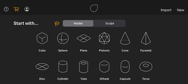
The first opportunity to create a parametric shape comes directly when creating a new project. You will find all available basic shapes as icons on the Start Menu page (see figure below).
Starting with a new project gives direct access to parametric objects directly from the Start Menu.
|
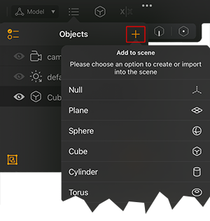
After selecting one of the shapes or just using the New command in the top right, Forger switches to the working layout. To add additional parametric objects to the project, just open the Objects List and click on its Plus (+) icon. This brings up a list of all available parametric objects. In addition, cameras and light sources can also be found in this menu, which can also be added to your scene in this way. |
|
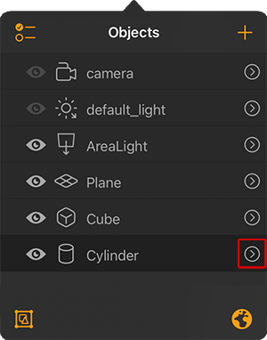
After adding the needed shape, you can proceed directly with the configuration of the selected object. To do this, open the Objects menu and select the entry of the object you want to customize. The arrow to the right of the object entry names will take you to the specific settings window. Alternatively, you can directly find the icon of the currently selected object in the upper main menu bar. A click on it also opens the settings window of this object, without you having to switch to the Objects list first. |
|
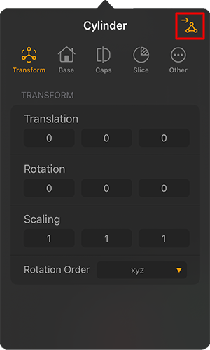
The Transform settings are not specific to parametric object. They are available for all object types and allow the exact placement and scaling of objects, including cameras and lights. |
|
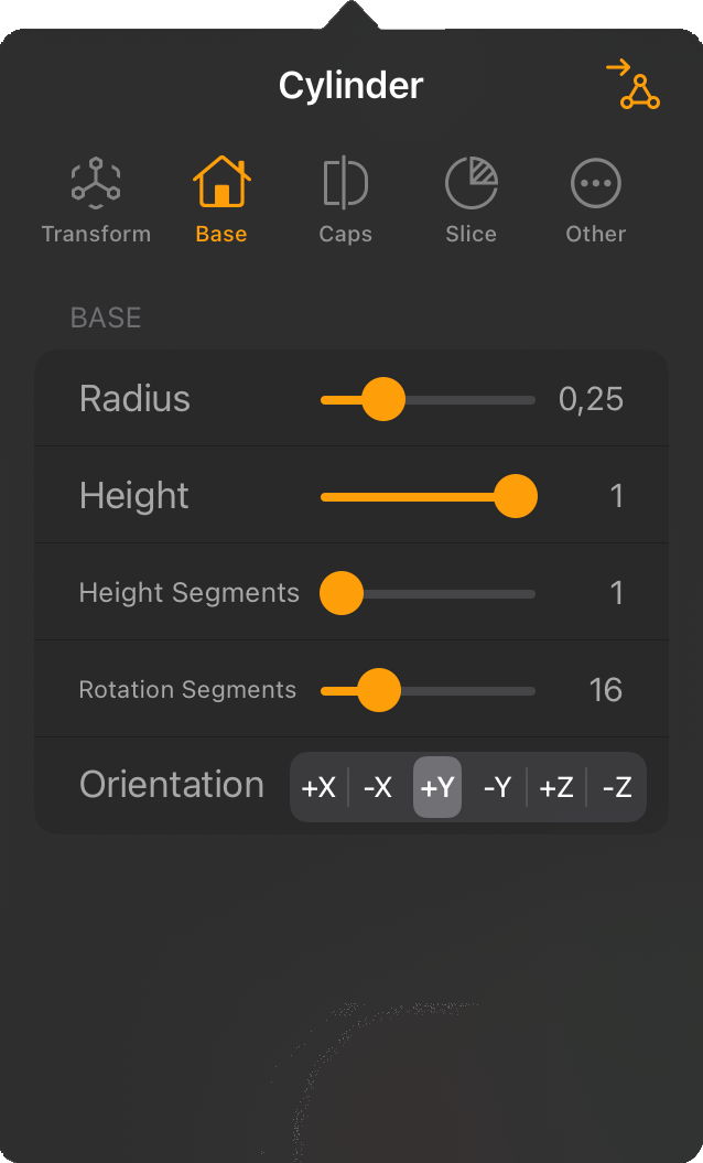
In the Basic tab you will find the basic settings of the object, which are mainly used to define its size and proportions. These settings are specific to the selected object. Rotationally symmetrical objects, such as a sphere, cone or cylinder offer radius values, angular shapes, such as a cube or plane are defined by dimensions along their axes. Segment settings generally determine the number of polygons on the object and can influence the quality of the shape display, especially for rotationally symmetrical objects. |
|
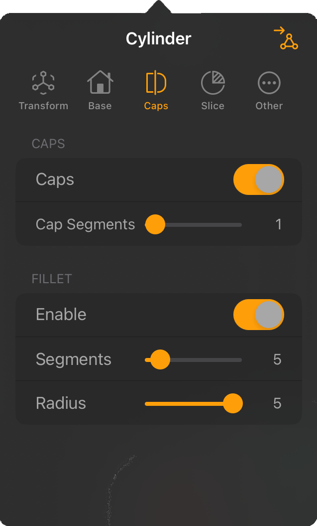
The Caps settings are available only on the objects that have disk-shaped areas that can be used to close the top and bottom of the basic shape. For example, think of a cylinder that can be closed at the top and bottom. Without this area, the cylinder becomes an open tube. |
|
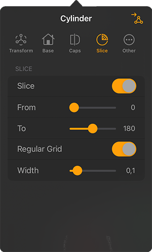
Some rotationally symmetrical objects, such as a Cylinder or a Cone, can also be created only in a section or a slice. For this purpose, an angle range to be displayed can be activated in this Slice tab. |
|
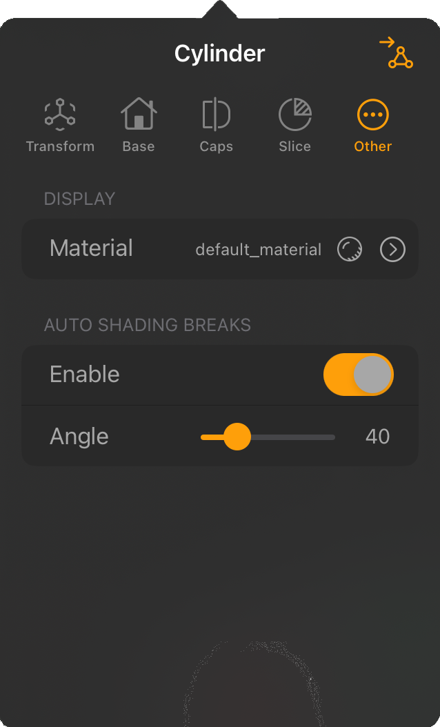
The Other tab is again not specific to parametric primitive objects, as materials can be assigned here or the shading angle of the surface can be defined. For more information on creating, applying and editing materials, click here. |
This object is always useful when modeling cables, hoses, pipes or similar shapes. The basis for this is a spline curve through which the center line of the hose shape runs. This curve can be drawn as a freehand line or created point by point in its course. For this purpose, the Sweep Object provides its own spline drawing tool, which is also used by the Lathe Object. You will therefore find many parallels in the creation of a Sweep Object and a Lathe Object.
Activating the Sweep Tool in the Toolbar displays new icons in the left menu bar, which are described below.
|
|
|
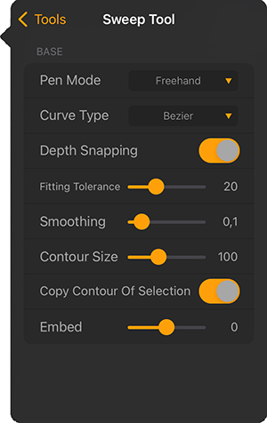
Besides the options available as icons, you can also open the settings of the Sweep Tool to configure, for example, the type of spline drawn and its interpolation. These settings must be made before drawing the curve.
|
|
After a spline curve is drawn, you can still add additional points and control the shape of the curve by moving the existing points. If the Bezier Curve Type has been used, all tangents can also still be rotated and scaled to control the curvature of the spline. Tangents can even be switched between hard and soft interpolation, and both tangents of a spline point can be broken. The following pictures show some examples of this and how it is done.
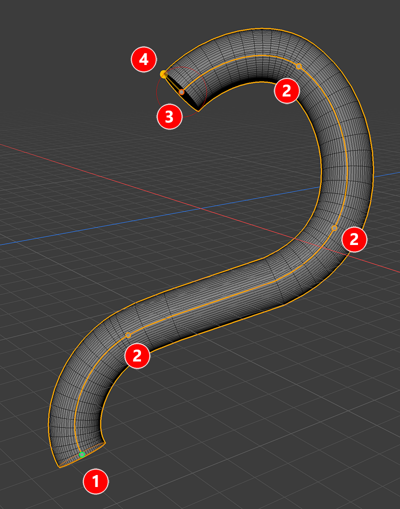 Example of a drawn Bezier curve used to create a Sweep Object.
As you can see in the image above, the curve always starts with a green point (1) and ends with a red point (3). If you decide to add an additional spline segment afterwards, it will always be attached to the red endpoint of the curve. Attached to the end there is also always an additional handle point attached to the side (4). Moving this point will scale the Contour Size, defining the radius of the circle used to create the tubular Sweep Object. The other points along the curve (2) define the curvature and shape of the spline. All points can be moved to shape the curve to your liking. You can also select multiple points at once using the + and - selection modifier keys.
When you tap on a point, an additional set of icons will appear and you will have access to the tangents of that point if a Bezier curve was used.
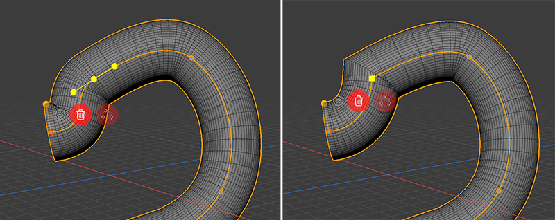 Switching between soft (left) and hard tangent interpolation (right)
With a double tap on a point along the curve, you can switch between the soft interpolation of the tangents and the hard interpolation of that point. This way you can mix organic and curvy spline parts with linear interpolated segments as shown in the image above. Having a point selected will also give access to three new icons that are displayed below the point by default. We walk though them from left to right:
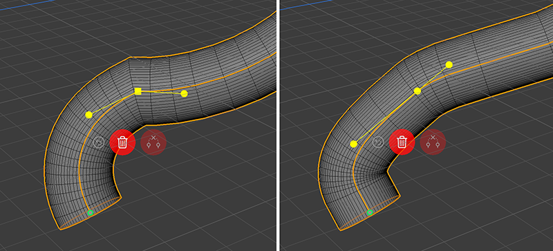 Switching the orientation of the Bezier tangents
The endpoints of the tangents can be moved directly to edit the length and direction of the tangents. In addition, a double tap on these endpoints can be performed to toggle constraints for the tangent directions and lengths. The current state is indicated by the shape of the spline point. A square point allows individual configuration of both tangents at this point (see left side of figure above). This allows them to point in different directions and have different lengths. With a circular spline point, both tangents remain on one continuous line (right side in the figure above).
By default, the Sweep Object is used with a perfect circle as a contour, resulting in a tube like object, but this circle curve can also be edited by manually moving its four points. You already have seen, that the radius of this Contour circle can be edited directly by moving the side handle at the red endpoint of the sweep curve or by using another Contour Size value in the Sweep Tool settings. To change the shape of the circle contour, tap once on the contour at the green starting point of your curve. this will give access to the fours points that define the circle contour. You can then select and move these countour points to your liking, work with their tangents or even add and delete points at the contour. The following image captures these steps.
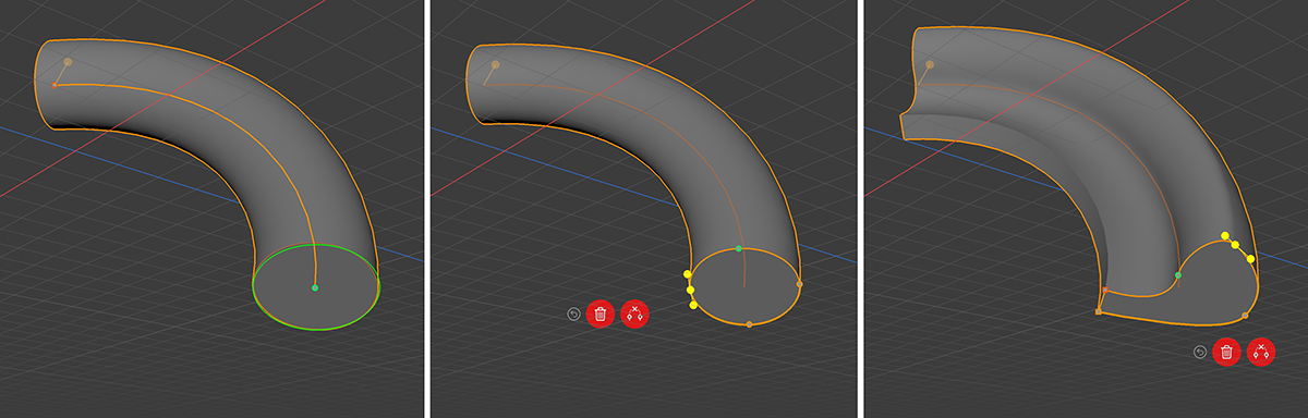 Editing the shape of the contour spline
The above image highlights the contour spline at the starting point of the Sweep curve on the left in green color. Just tap this contour to get access to the points along that contour and edit this curve to your liking (see right image above). You can even tap on the curve to add more points to it or use the trash can icon below to delete selected points that are not needed. If you like to use the modified contour also for the next created Sweep Objects, take care to activate the Copy Contour Of Selection option in the Sweep Tool settings before drawing the next Sweep Object.
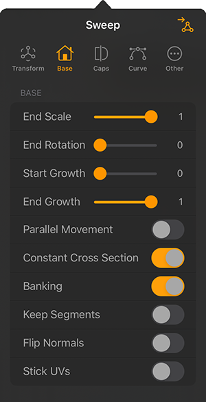
The shape and style of the created Sweep Object can be further edited by opening the Sweep Object settings.
|
The Base Settings
|
|
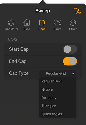
The Caps Settings
|
|
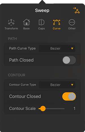
The Curve Settings
|
The Lathe Object is always suitable for modeling when rotationally symmetrical objects are to be created, such as a bottle, a vase or a glass. These shapes can be modeled by drawing a half cross-section of, for example, a vase as a spline curve (Contour Spline). By rotating this curve around a perpendicular axis, the complete object is then created. An additional option allows the contour curve to be moved along the vertical while rotation takes place at the same time. In this way, snail shells or, for example, corkscrew shapes can also be created.
After activating the Lathe Tool, the creation takes place in two steps:
Tap once in the viewport or drag a held tap around in the viewport to place the origin system for creating the Lathe shape. The representation of this system consists of a vertical line by which the axis of rotation is indicated. When subsequently drawing the Contour spline, it should always be on one side of this axis only.
After placing the virtual potter's wheel of the Lathe Tool, the tool automatically switches to the drawing mode and you can directly start creating the Contour. The Lathe tool provides the following options for this purpose:
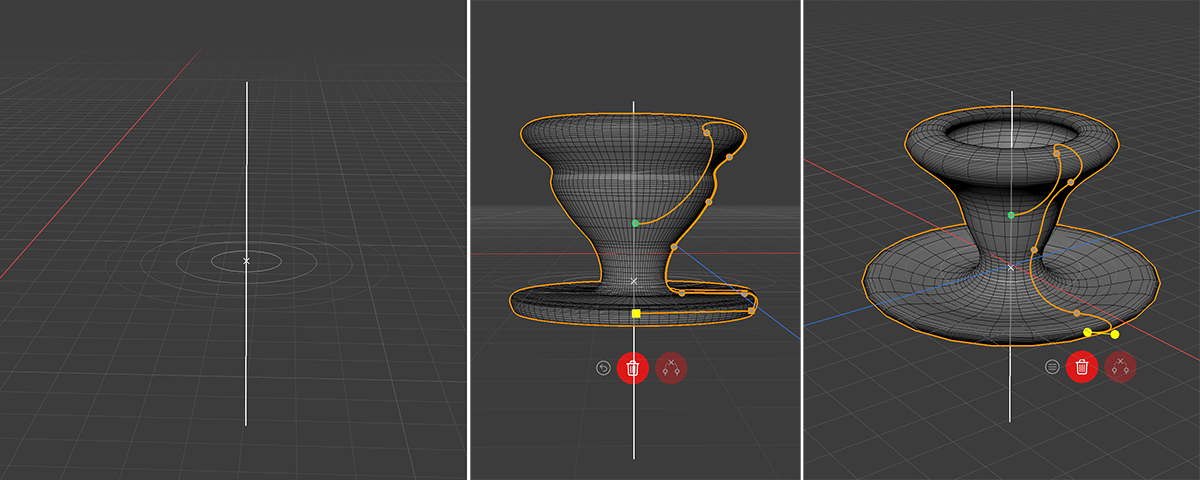 The two steps of the Lathe Object creation: On the left, the origin system of the Lathe has been placed and on the right you can see different perspectives of drawn Contour curves and how they get rotated and duplicated around the rotation axis to shape the object.
|
|
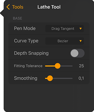
While drawing the contour spline the Lathe Tool offers the same options as icons in the left Toolbar as the Sweep Tool. Just can find all info about these icons here.
Also editing the Lathe Contour splines works just the same as editing the Sweep spline. You can read about these options here.
The shape and style of the created Lathe Object can be further edited by opening its settings.
|
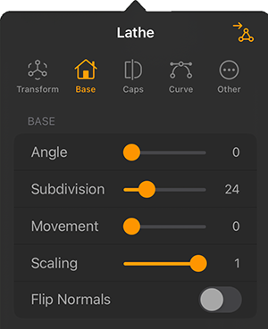
The Base Settings
|
Flip Normals: Flips (i.e. reverses the direction of) the Normals of the Lathe Object. Usually, Forger will point the Normals in the correct direction. However, with open contours it is not possible for Forger to know which way they should point. In this case, you can reverse the direction of the Normals with this option, if needed. This option does not effect the caps, since their Normals are always calculated correctly.
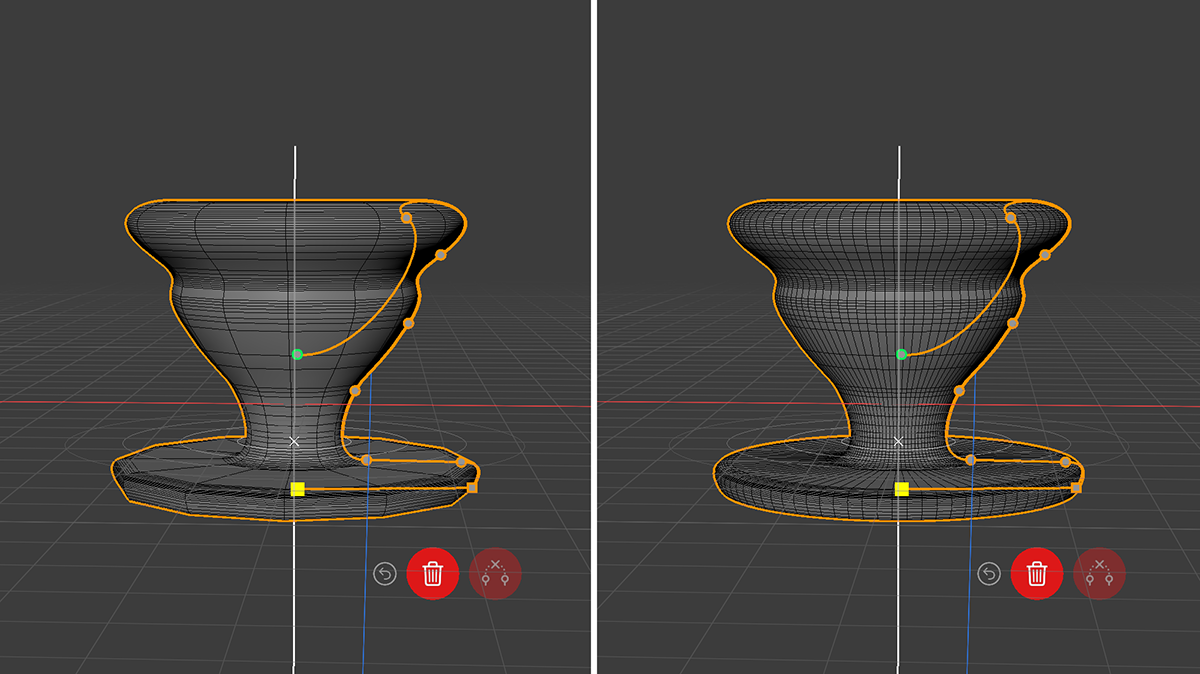 Example of the same Contour spline used, but with a low Subdivision (left side) and a higher Subdivision (right side).
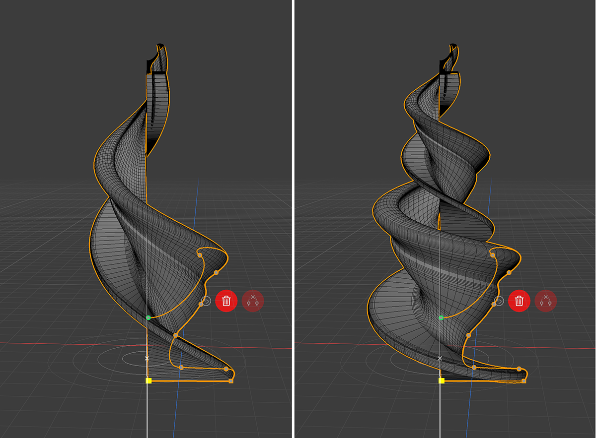 Example of on increased Movement value in combination with a reduced Scaling value. On the right side the Angle value has been increased over 360° to add even more twists to the shape.
|
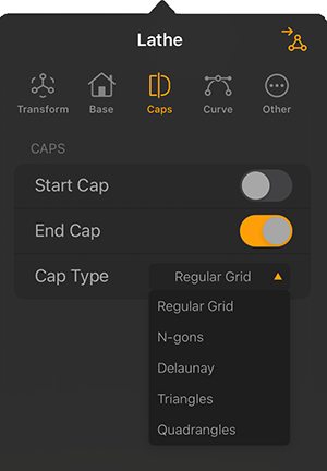
The Caps Settings
|
Caps can only be created, if a closed Contour spline was used. The following image gives an example, using a reduced Angle value for the Lathe Object to make the Start and End Caps visible.
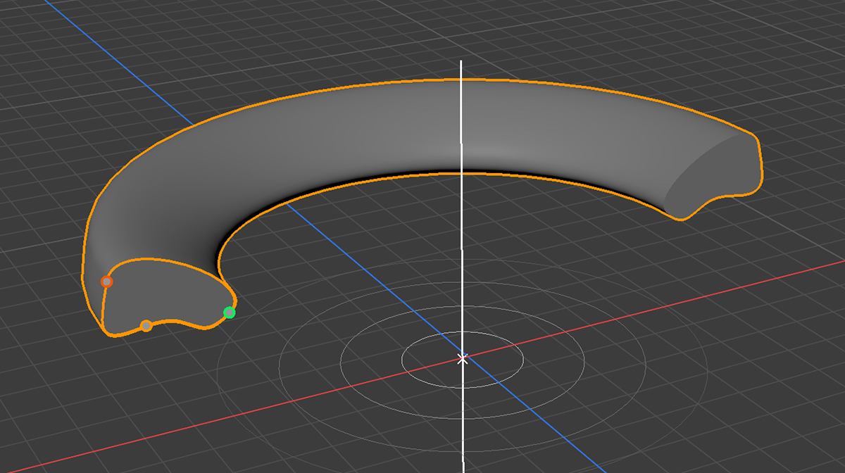 Contours can be closed with Caps
|
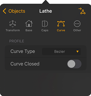
The Curve Settings
|
This object is highlighted separately here because, although it can also be counted among the parametric objects, it does not itself provide any points, edges or polygons. Rather, it consists only of an axis system that can be highlighted by various shapes. The Null Object therefore does not react to light and cannot be covered with materials.
Nevertheless, a Null Object can be very useful if, for example, various objects are to be grouped together. In this case, simply create a Null Object and place it at the coordinate in the scene that is to serve as the position or pivot point for rotations. Then arrange the objects to be grouped as child objects under the Null Object. Any change in Translation, Rotation, Scaling and even its Visibility state is then transfered to all child objects as well. For more information, about how to create such groups, have a look at the Objects List.
Null Objects can also be used to control the position of the focal plane if they get linked to the cameras Depth of Field settings or the global Depth of Field Display settings.
These are the specific settings of a Null Object:
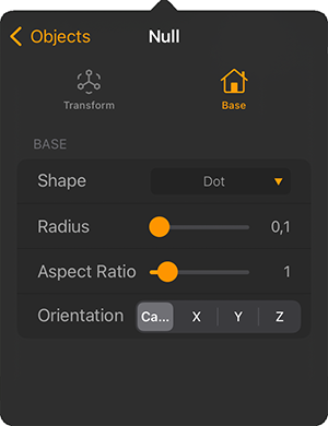
|
|

|
Here you can see the representation of a Null Object for which a Diamond Shape has been selected. This shape was enlarged using the Radius value and automatically aligned with the Camera using the Orientation setting. When the Null Object is selected, its axis system becomes visible at the same time (see upper part of the illustration). Otherwise, in the deselected state, only its position as a point and the selected Shape are visible. |