Strokes
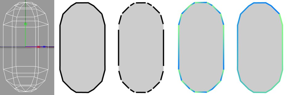 Figure 1 to 5
When Sketch and Toon creates lines for an object, the lines are initially made up of unconnected line segments. You can see the line segments for the capsule above clearly in Figure 3, where a gap has been placed between each line segment for illustrative purposes.
The Enable option on the Strokes tab controls whether Sketch and Toon tries to connect line segments together to form strokes. The advantage of strokes is that you can apply effects such as a gradient over the stroke as a whole. Figure 4 shows what happens when a gradient is applied to unconnected line segments — the gradient is applied to each individual segment instead of to the outline as a whole. Contrast this with Figure 5, where strokes have been enabled.
In general, enable strokes when you want to apply an effect over multiple line segments; otherwise, leave strokes disabled. Note that if this option is disabled, artefacting can occur at the beginning or end of individual line segments (but rendering will be faster).
This switches on Strokes.
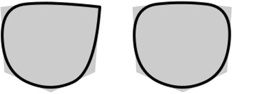 Close Path disabled (left) and enabled (right) for a cube’s distorted outline.
If Close Path is enabled, Sketch and Toon will try to join the start and end of the stroke.
Match, Threshold, Distance, Join Limit
Although the lines generated by Sketch and Toon come from a 3D scene, the lines themselves are only 2D because they are drawn flat onto the screen. This means you can get line segments that overlap on the screen and could be connected that are actually from different depths of the scene. These settings tell Sketch and Toon how to deal with such line segments. You can set Match to the following modes.
This mode ignores the Z-depth and treats all lines as purely 2D; this essentially flattens the image and lets line segments be connected together even if they are at different depths in the scene.
The Nearest mode connects to the line that is the minimum Z-depth away. Note that this does not always produce the desired results. Sometimes if you have lots of very small lines close to one another, the nearest connection may not be the best one! If strokes start breaking up, try using Depth mode instead, and if that does not help, try Flat, which allows all possible connections.
Keep in mind that when strokes break up, it is usually a sign that there are problems with the mesh; for example, perhaps the mesh contains non-planar polygons — these are best avoided when using Sketch and Toon. Use clean simple mesh for best results.
In Depth mode, you can specify the maximum difference in Z-depth to allow for connections.
This matches the Z in world coordinates. This is good for contour lines where you want line segments from the same contour to connect.
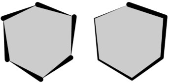 Low Join Limit value (left) and high Join Limit value (right).
This is one of the most important settings on the Strokes tab. It prevents neighboring line segments from being joined together if the angle between them exceeds the Join Limit value. This helps to prevent very long strokes and speeds up the calculation of strokes by limiting the number of possible connections.
When strokes are generated, a small number of lines are often left over and form very small strokes or no strokes at all. These tend to look like artifacts or blobs. Enable the Filter Strokes option to remove these unwanted lines.
There are three modes for the strokes filter. Overlap is the best one and is especially good at removing overlaps and small strokes. However, it is also the slowest mode.
The Pixel mode filters all strokes below the Length value (in pixels). However, the problem with this mode is that if you zoom the objects or scale them, the filter removes more or less because the pixel size of the stroke has changed.
This mode also filters strokes below the Length value. The difference is that in this mode the Length is specified as a percentage of the object’s screen bounds maximum, i.e., its width or height, whichever is greater. This enables you to move or zoom objects without the effect changing.
Overlap is an intelligent mode. First it looks for overlapping strokes. When it finds them, it filters the shorter stroke if it is shorter than the Length value and within the Distance value of the longer stroke, where a Length value of 100% and a Distance value of 100% correspond to the longer stroke’s length and Thickness value (Thickness tab).
See Mode.
See Mode.
See Mode.
See Mode.
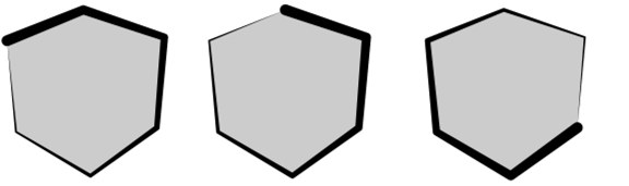 Various starting positions for the stroke using the Start and Angle settings.
These settings influence the starting position of strokes. Note that the starting point is only a guide for Sketch and Toon. Sketch and Toon will try to start here, but the stroke may start from an earlier point if it can do so. You can set Start to the following modes.
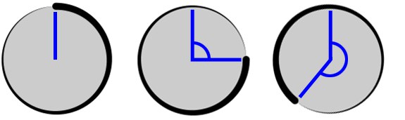 From left to right: Angle set to 0°, 90° and 220°.
Sketch and Toon will try to start drawing the strokes from the angle you specify, where 0° means from the center of the screen or object upwards (left sphere above).
This starts each stroke from an available line segment chosen at random.
In Mesh mode, the stroke starts with the oldest available edge (i.e. the one with the lowest index number in the Structure manager).
Each stroke starts with the line segment closest to the left, right, top or bottom edge that is still available.
The Inner and Outer modes start the stroke with the first available line segment closest to or furthest away from the object’s center.
Stylized strokes may lead to problems when animated. This is because the lines and their possible connections change from frame to frame, causing various jumping and popping effects. The Frame Match options are designed to help overcome these issues. They attempt to match up the strokes generated for the current frame with the strokes from the previous frame. For best results, avoid major changes from frame to frame.
See Start.
This sets the direction in which Sketch and Toon tries to draw the stroke: clockwise, anti-clockwise, left, right, up or down. If a stroke is not possible in this direction, Sketch and Toon will try to draw the stroke in the opposite direction instead. Sketch and Toon also checks the opposite direction once the end of a stroke has been reached and extends the stroke in this direction if it can.
These settings control when Sketch and Toon ends a stroke. If End is set to Off, Sketch and Toon will create each stroke until it cannot continue anyway (i.e. until it runs out of suitable connections).
The other modes — Length, Angle and Joint — end the stroke once it is longer than a set length (defined in pixels); when the angle to the next line segment is greater than a set angle; or when the stroke meets two or more line segments and has a choice of which path to take.
Stylized strokes may lead to problems when animated. This is because the lines and their possible connections change from frame to frame, causing various jumping and popping effects. The Frame Match options are designed to help overcome these issues. They attempt to match up the strokes generated for the current frame with the strokes from the previous frame. For best results, avoid major changes from frame to frame.
See End.
The Variation settings vary the set length and angle per stroke as a percentage.
See End.
The Variation settings vary the set length and angle per stroke as a percentage.
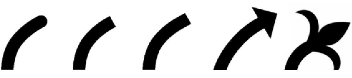 Round, Flat, Square, Arrow, Custom
These setting control the shape of the cap at the start and end of each line. You can choose from shapes such as Flat or Arrow or you can load an image and use it as a custom shape (set Start Cap or End Cap to Custom and use the Texture button to load the image).
The Width and Height settings specify the width and height for arrow caps or custom caps. Keep in mind caps take longer to render the larger they are.
The Width and Height settings specify the width and height for arrow caps or custom caps. Keep in mind caps take longer to render the larger they are.
Use the Texture button to load the image.
Round, flat, quadrangle, arrow, customUse this setting to define the look of the line end. One of the default end cap shapes can be used or a texture can be loaded instead, whose shape will then be used.
Use this setting to define the cap width. Larger caps will take longer to render.
Use this setting to define the cap height. Larger caps will take longer to render.
The Texture button can be used to freely define line ends, load a texture or apply a shader.
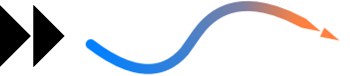 Image used as a custom cap (left) and the cap applied to the end of a stroke with Width set to 800% and Height set to 100% (right). Note how the cap adopts the stroke’s properties such as color and thickness — the cap effectively becomes part of the stroke.
The image for a custom cap should show the cap pointing to the right (see the double-arrow example above). Solid parts of the cap should be black, transparent parts white. Values between black and white represent semi-transparency.
Choose the shape of the joints: Miter, Bevel or Round.
 Miter, Bevel, Round
Miter joints take longer to render than Bevel joints and Round joints. However, you can optimize their rendering speed using the Miter Limit value. The optimum setting is the smallest angle of any joint.
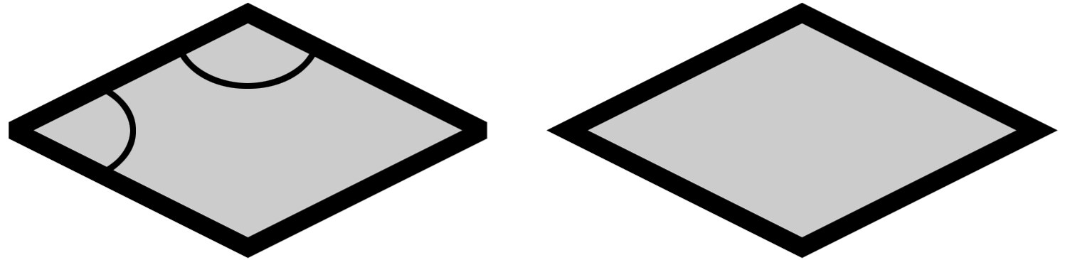
Increase the value for faster rendering but avoid setting it higher than the smallest angle or some or all of the joints will be rendered blunt instead of sharp (left diamond).
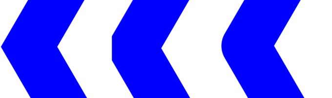
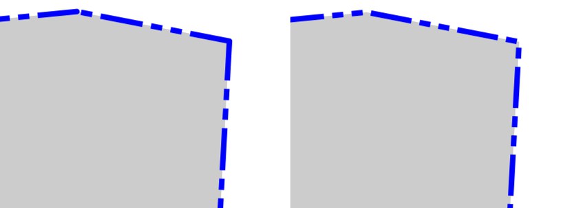 A pattern with strokes disabled (left) and enabled (right). Enabling strokes allows the pattern to be continuous over multiple line segments.
The Pattern settings give a pattern to the lines such as dashes or dots. These patterns are mostly useful for technical illustrations. If you want the pattern to be continuous over multiple line segments, ensure that strokes are enabled. You can choose from various preset patterns or, to define a custom pattern.
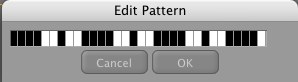
Click the Edit button and use the Edit Pattern dialog (click or drag over bars to turn black bars to white and vice versa).
Use this setting to offset the line start.
Use this setting to scale the line length.