Thickness
These three tabs give you complete control over the color, thickness and opacity of lines. They enable you to create any type of line effect, from simple lines that fade out to complex brush effects. Each tab works in a similar way:
- Set the general color, thickness and opacity using the Color, Thickness and Opacity settings at the top of the tabs.
- Modify the color, thickness and opacity using the modifier options. To switch on a modifier, enable its option. You will see its settings appear in the bottom part of the tab, where you can adjust them.
With a few exceptions, each tab has the same modifier options. For example, the Along Stroke modifier is present on all three tabs.
Thin out and fade the lines as they get further away from the object or polygon selection.
![]() Modifiers
Modifiers
Distance
Position
Scale
Illumination
Vertex Map
Texture Map
Screen Texture
Along Stroke
Total Length
Facing Angle
Join Angle
Screen Angle
Noise
Python
Activate the desired modifier here:
![]() Python
Python
In order to use this very powerful modifier, you should have a good command of Python, which is the script language implemented by Cinema 4D. For details about the Python programming language, visit http://developers.maxon.net.
The Python modifier lets you create virtually any medium or style, from a simple pencil to a complex brush.
Defines the strength of the effect - 0% = no effect; 100% = full effect.
Enter your Python script into the Script field.
Enter a script into the Script box or click the Expresson Editor button and enter the script into Cinema 4D’s script editor.
This acts as a quick reference to look up the names of the commands. It has no other purpose. It does not insert commands.
Position along a line in pixels (screen space).
Normalized position along a line (0 to 1).
Distance to the line from the current render point (which is within the line’s thickness). Values range from - Thickness to 0 to Thickness.
The line’s thickness as set on the [Thickness] tab.
The total length of the stroke being rendered.
The render point in screen space (with Z).
The offset (0 to 1) along the line segment being rendered.
The world coordinates for the point being rendered.
Current document time in seconds.
Current frame.
Frames per second.
The screen space coordinates for the start of the line (LineOff = 0 at the LineStart, 1 at LineEnd).
Screen space for line segment’s end point.
Join angle to the line segment at LineStart (if available, or 0.0).
Join angle (0 to 2*pi) to the line segment at LineEnd.
The line normal in screen space (2D, Z=0).
The normal from the edge that created the original line segment.
The line segment’s position along the stroke in pixels (A means LineStart, B LineEnd).
The position along the stroke in screen space for the line segment being rendered.
The index number of the object point or spline point that created the start of the line segment (or -1 if not available).
The point index that created the LineEnd (or -1).
The polygon index that created the line segment (or -1 if not available, like a spline).
The polygon index that shared the edge (or -1 if not available).
This passes in the raybits from the Cinema 4D render. See the Cinema 4D SDK.
The angle between the ray and normal on the surface.
The normal from the surface (if PolyHit is not 0, which says it hit an object).
Bumped surface normal.
Distance to the point hit on the surface (if one was hit).
Really only useful to know if an object was hit by a ray, which means the value is not 0.
World position for the ray’s starting point.
Direction of the ray (the ray is from Cinema 4D).
The world coordinates for the point hit (if one was hit).
The render image left pixel.
Render top pixel (left, top usually 0, but not always, e.g render region).
Right pixel (width = right-left+1).
Bottom pixel (height = bottom - top +1).
Object’s left screen bounds pixel. This is for the object that the line came from. This is not necessarily the object hit by the Cinema 4D ray.
Object’s top screen bounds pixel.
Object’s right screen bounds pixel.
Object’s bottom screen bounds pixel.
The color set in the [Color] tab (Color parameter only).
![]() Distance
Distance
 Original, color, thickness, opacity, all three
The Distance modifier changes the color, thickness or opacity of lines in relation to their distance from the camera.
Defines the strength of the effect. 0% = no influence, 100% = maximum influence.
The Range setting defines the range over which the color, thickness or opacity is modified.
This range is from the part of the object nearest the camera to the part furthest away.
This uses the camera’s Front Blur End and Rear Blur End values (Depth tab) when you enable them. If the options are disabled then Sketch and Toon will use the Target Distance in place of Rear Blur End and the Camera in place of Front Blur End.
When you select the Custom range, you will see the Min and Max boxes appear. These define the start and end of the range as distances from the camera.
Not all modifiers offer different modes from which to select.
 A Distance modifier set to Linear mode in the Thickness tab. The graph controls the thickness of the line in relation to its distance from the camera.
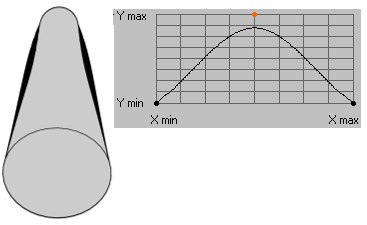 Spline mode for the Thickness Tab’s Distance modifier. In the image above, the graph defines the thickness of the line in accordance with its distance from the camera.
Use this mode to define how thickness or opacity should influence a particular area. The Linear mode mixes line thickness or opacity evenly over a given area. The Invert option will reverse the direction of the mixing. If, on the other hand, you set Mode to Spline, a spline graph will appear in which you can draw a gradient that will influence thickness and opacity. The X axis represents the area from start to end of a given line, the Y axis represents its thickness or opacity.
![]() Position
Position
 From left to right: Original, color. thickness, opacity, all three
The Position modifier modifies the color, thickness or opacity based on the object’s scale along an axis.
Defines the strength of the effect. 0% = no influence, 100% = maximum influence.
Axis represents the camera axis to use. The Min and Max values define range over which the parameter is modified. For example, if Axis is set to Z and Min and Max are set to 500 m and 1000 m respectively, the range is from 500 m to 1000 m along the camera’s Z axis.
Not all modifiers offer different modes from which to select.
A Distance modifier set to Linear mode in the Thickness tab. The graph controls the thickness of the line in relation to its distance from the camera.Spline mode for the Thickness Tab’s Distance modifier. In the image above, the graph defines the thickness of the line in accordance with its distance from the camera.Use this mode to define how thickness or opacity should influence a particular area. The Linear mode mixes line thickness or opacity evenly over a given area. The Invert option will reverse the direction of the mixing. If, on the other hand, you set Mode to Spline, a spline graph will appear in which you can draw a gradient that will influence thickness and opacity. The X axis represents the area from start to end of a given line, the Y axis represents its thickness or opacity.
See axis.
![]() Scale
Scale
The Scale modifier modifies the color, thickness or opacity based on the object’s scale along an axis.
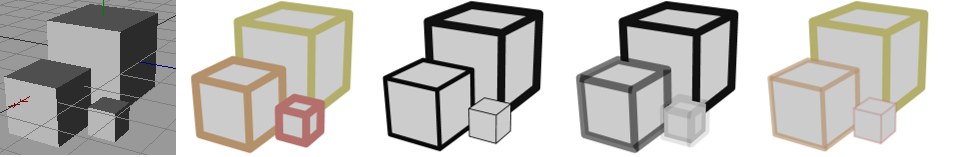 From left to right and top to bottom: Original, color, thickness, opacity, all three
This modifier is based on the scale — not the size — of the objects!
Defines the strength of the effect. 0% = no influence, 100% = maximum influence.
Defines which axis (X, Y or z Z) should be used.
The Coordinates setting lets you choose whether this axis is an object axis (Local) or world axis (World). For example, if you set Axis to Y and Coordinates to Local, the lines will be modified based on the scale of the object’s Y axis.
A custom range is always used on the Color tab. Set the range using the Min and Max boxes.
This is the range of scales over which the parameter is modified. If Range is set to Scale, the range is from a scale of 0 to 1. To define your own range, set Range to Custom and enter the minimum and maximum scale into the Min and Max boxes.
Not all modifiers offer different modes from which to select.
A Distance modifier set to Linear mode in the Thickness tab. The graph controls the thickness of the line in relation to its distance from the camera.Spline mode for the Thickness Tab’s Distance modifier. In the image above, the graph defines the thickness of the line in accordance with its distance from the camera.Use this mode to define how thickness or opacity should influence a particular area. The Linear mode mixes line thickness or opacity evenly over a given area. The Invert option will reverse the direction of the mixing. If, on the other hand, you set Mode to Spline, a spline graph will appear in which you can draw a gradient that will influence thickness and opacity. The X axis represents the area from start to end of a given line, the Y axis represents its thickness or opacity.
This is the area over which the setting will be modified. If the area is set to Size the range will be from 0 to 1. To define an area manually, select Manual and define the area accordingly. Max [0..+∞]
![]() Along Stroke
Along Stroke
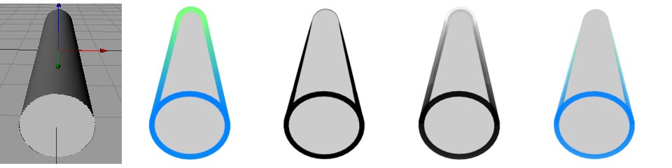
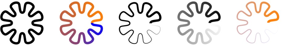 Original, color, thickness, opacity, all three.
This modifier modifies color and the thickness and/or opacity based on their position along the strokes.
Defines the strength of the effect. 0% = no influence, 100% = maximum influence.
The Range setting defines the range over which the color, thickness or opacity is modified.
The range runs from the beginning to the end of the stroke or segment.
When you select the Custom range, you will see the Min and Max boxes appear. These define the start and end of the range as distances from the camera.
Not all modifiers offer different modes from which to select.
A Distance modifier set to Linear mode in the Thickness tab. The graph controls the thickness of the line in relation to its distance from the camera.Spline mode for the Thickness Tab’s Distance modifier. In the image above, the graph defines the thickness of the line in accordance with its distance from the camera.Use this mode to define how thickness or opacity should influence a particular area. The Linear mode mixes line thickness or opacity evenly over a given area. The Invert option will reverse the direction of the mixing. If, on the other hand, you set Mode to Spline, a spline graph will appear in which you can draw a gradient that will influence thickness and opacity. The X axis represents the area from start to end of a given line, the Y axis represents its thickness or opacity.
See Range / Custom.
Defines how often a given line should be repeated.
![]() Total Length
Total Length
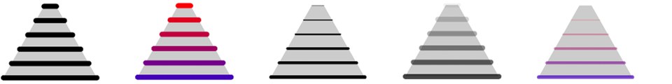 From left to right and top to bottom:
Original, color, thickness, opacity, all three.
These define the minimum and maximum line length in pixels over which the parameter is modified.
The Total Length modifier modifiers the color, thickness or opacity based on the length of each stroke (or line segment if strokes are disabled).
Defines the strength of the effect. 0% = no influence, 100% = maximum influence.
Use this setting to define the minimum line length in pixels over which the setting should be modified.
Use the Max setting to define the maximum line length in pixels over which the parameter should be modified.
Not all modifiers offer different modes from which to select.
A Distance modifier set to Linear mode in the Thickness tab. The graph controls the thickness of the line in relation to its distance from the camera.Spline mode for the Thickness Tab’s Distance modifier. In the image above, the graph defines the thickness of the line in accordance with its distance from the camera.Use this mode to define how thickness or opacity should influence a particular area. The Linear mode mixes line thickness or opacity evenly over a given area. The Invert option will reverse the direction of the mixing. If, on the other hand, you set Mode to Spline, a spline graph will appear in which you can draw a gradient that will influence thickness and opacity. The X axis represents the area from start to end of a given line, the Y axis represents its thickness or opacity.
![]() Facing Angle
Facing Angle
 From left to right and top to bottom:
Original, color, thickness, opacity, all three.
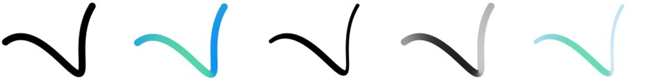
The Facing Angle modifier modifies the color, thickness or opacity based on the direction in which the lines are facing relative to the camera. Hidden lines are also affected if shown.
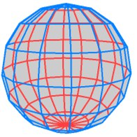 Blue visible lines and red hidden lines via the Facing Angle modifier.
Defines the strength of the effect. 0% = no influence, 100% = maximum influence.
Not all modifiers offer different modes from which to select.
A Distance modifier set to Linear mode in the Thickness tab. The graph controls the thickness of the line in relation to its distance from the camera.Spline mode for the Thickness Tab’s Distance modifier. In the image above, the graph defines the thickness of the line in accordance with its distance from the camera.Use this mode to define how thickness or opacity should influence a particular area. The Linear mode mixes line thickness or opacity evenly over a given area. The Invert option will reverse the direction of the mixing. If, on the other hand, you set Mode to Spline, a spline graph will appear in which you can draw a gradient that will influence thickness and opacity. The X axis represents the area from start to end of a given line, the Y axis represents its thickness or opacity.
![]() Join Angle
Join Angle
This modifier works with strokes only.
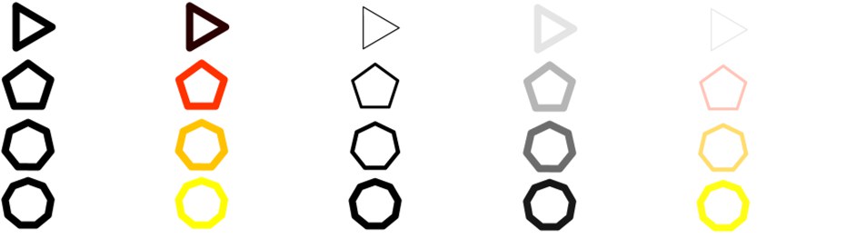 (Original), color, thickness, opacity, all three
The Join Angle modifier modifies the color, thickness or opacity based on the angle of the joints in the stroke.
Defines the strength of the effect. 0% = no influence, 100% = maximum influence.
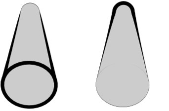
Use this setting to define the look of the line tips.
When in this mode, the parameter’s values will remain unchanged at both start and end of a given line. For example, if Thickness is set to 12 pixels in the Thickness tab the line will be 12 pixels thick at its start and at its end.
Minimum Angle
Zero Angle
Maximum Angle
Depending on the option selected, the line ends will reflect minimum, maximum or zero angle.
Not all modifiers offer different modes from which to select.
A Distance modifier set to Linear mode in the Thickness tab. The graph controls the thickness of the line in relation to its distance from the camera.Spline mode for the Thickness Tab’s Distance modifier. In the image above, the graph defines the thickness of the line in accordance with its distance from the camera.Use this mode to define how thickness or opacity should influence a particular area. The Linear mode mixes line thickness or opacity evenly over a given area. The Invert option will reverse the direction of the mixing. If, on the other hand, you set Mode to Spline, a spline graph will appear in which you can draw a gradient that will influence thickness and opacity. The X axis represents the area from start to end of a given line, the Y axis represents its thickness or opacity.
![]() Screen Angle
Screen Angle
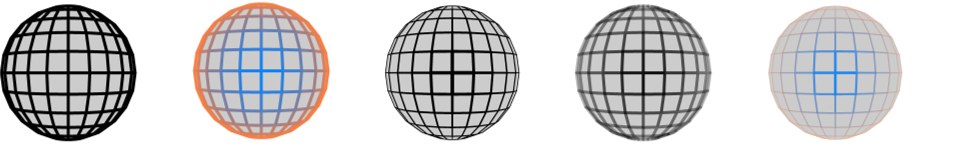
 Original, color, thickness, opacity, all three.
The Screen Angle modifier modifies the color, thickness or opacity based on the line’s direction on the computer screen.
Defines the strength of the effect. 0% = no influence, 100% = maximum influence.
Not all modifiers offer different modes from which to select.
A Distance modifier set to Linear mode in the Thickness tab. The graph controls the thickness of the line in relation to its distance from the camera.Spline mode for the Thickness Tab’s Distance modifier. In the image above, the graph defines the thickness of the line in accordance with its distance from the camera.Use this mode to define how thickness or opacity should influence a particular area. The Linear mode mixes line thickness or opacity evenly over a given area. The Invert option will reverse the direction of the mixing. If, on the other hand, you set Mode to Spline, a spline graph will appear in which you can draw a gradient that will influence thickness and opacity. The X axis represents the area from start to end of a given line, the Y axis represents its thickness or opacity.
The Rotate setting lets you rotate the modifier’s effect.
![]() Vertex Map
Vertex Map
This modifier is available on the Thickness and Opacity tabs only.
 Original, thickness, opacity
The Vertex Map modifier modifies the thickness or opacity based on a vertex map. To choose which vertex map is used, assign a Sketch Style tag to the object if it does not have one already and set the map on the tag’s Maps tab (Drag & drop the tag into the Thickness Map or Opacity Map box).
Defines the strength of the effect. 0% = no influence, 100% = maximum influence.
![]() Texture Map
Texture Map
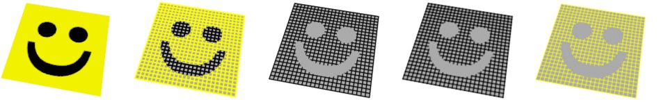 Texture, color, thickness, opacity, all three
The Texture Map modifier modifies the color, thickness or opacity based on a texture map.
 Color tab.
Defines the strength of the effect. 0% = no influence, 100% = maximum influence.
Load the texture that should affect the strokes here.
This is the projection to use for the texture map, such as UVW, Flat or Spherical.
Use this setting to offset scale and texturing in the U direction.
Use this setting to offset scale and texturing in the V direction.
Use this setting to offset scale and texturing in the U direction.
Use this setting to offset scale and texturing in the V direction.
![]() Illumination
Illumination
 From left to right and top to bottom: Original illumination, color, thickness, opacity, all three.
The Illumination modifier modifies the color, thickness or opacity based on the illumination falling onto the line.
On the Color tab you can use the modifier in two modes: Intensity and Color.
Not all modifiers offer different modes from which to select.
A Distance modifier set to Linear mode in the Thickness tab. The graph controls the thickness of the line in relation to its distance from the camera.Spline mode for the Thickness Tab’s Distance modifier. In the image above, the graph defines the thickness of the line in accordance with its distance from the camera.Use this mode to define how thickness or opacity should influence a particular area. The Linear mode mixes line thickness or opacity evenly over a given area. The Invert option will reverse the direction of the mixing. If, on the other hand, you set Mode to Spline, a spline graph will appear in which you can draw a gradient that will influence thickness and opacity. The X axis represents the area from start to end of a given line, the Y axis represents its thickness or opacity.
Use this field to define whether the lights placed into this field should be included or excluded from a given effect.
Use Lighting to choose whether the lighting, shadows or both are used to modify the parameter.
Defines the strength of the effect. 0% = no influence, 100% = maximum influence.
Drag lights that should be included in rendering into this field.
![]() Noise
Noise
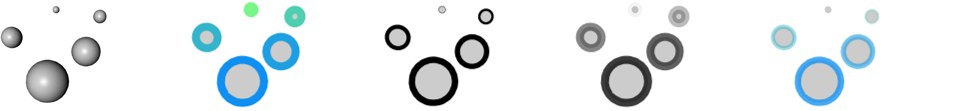
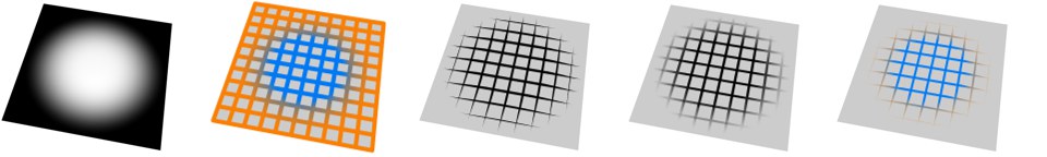
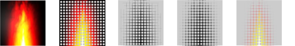
 Original, color, thickness, opacity, all three.
The Noise modifier modifies the color, thickness or opacity based on a noise pattern.
Defines the strength of the effect. 0% = no influence, 100% = maximum influence.
Choose from 30 types of noise such as Blistered Turbulence, Dents and Wavy Turbulence. These are the same types that are available for Cinema 4D’s Noise shader. Read more here.
This selection menu defines the coordinates that will be used to generate the noise. This can affect to the look of the noise, how it changes according to the camera’s movement or whether or not it continues in line segments once Strokes has been deactivated.
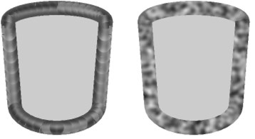 Strokes disabled (left) and enabled (right).
This modifier uses the position along the line. Avoid using this type if strokes are disabled, otherwise poor results are likely (see left cylinder above).
The noise is calculated in the space of the screen. The noise will change as the object’s position on the screen changes.
The noise is calculated in object space and remains the same regardless of object and camera moves.
The noise is calculated in world coordinates. The noise remains the same if you move the camera but changes if you move the object.
Controls the number of octaves over which the noise will span.
Use this setting to adjust the global expanse of the noise.
Use this setting to define the speed of the noise loops in loops per second.
Used for antialiasing. In general, leave the value set to the default of 100% but if the line texture flickers when you animate, try increasing the value. Or if you are rendering a high-res still and you want crisp detail, set the value lower.
The Low Clip value controls the bottom clipping value of the noise; all values below Low Clip will be clipped to zero.
The High Clip value controls the top clipping value of the noise; all values above High Clip will be clipped to 100%.
This controls the brightness of the lines as a percentage of the color sampled from the surface. In other words, the higher you set this value, the brighter the lines and the more they blend in with the image.
Use this setting to adjust the overall contrast of the noise. Values greater than 0 will increase contrast, values less than 0 will reduce contrast.
If this option is enabled, the noise is absolute, causing it to fold about its midpoint.
Enable this option to invert the effect.
![]() Screen Texture
Screen Texture
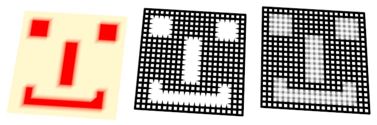
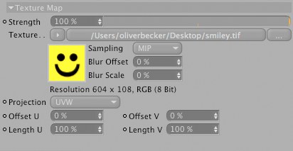
 From top to bottom and left to right: Texture, color, thickness, opacity, all three.
The Screen Texture modifier modifies the color, thickness or opacity based on a texture map placed over the entire rendered image (the screen). If the object covers only part of the screen, it will receive only part of the texture.
Defines the strength of the effect. 0% = no influence, 100% = maximum influence.
Use this setting to offset the text origin along the x axis on the screen.
Use this setting to offset the text origin along the Y axis on the screen.
Use this setting to offset scale and texturing in the X direction.
Use this setting to offset scale and texturing in the Y direction.