Globals
The settings on the Globals page control general parameters which describe the basic properties of a PyroCluster shader.
This page contains general settings for the selected PyroCluster shader.
The On/Off switch is especially useful when you are fine-tuning a scene. It allows you to turn the PyroCluster shader on and off for the selected material.
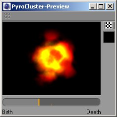
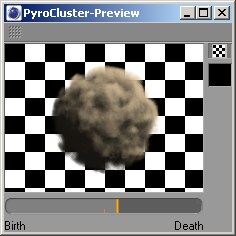
Some examples of using the PyroCluster preview, illustrating the use of the background option and the age slider. Changes to settings will be shown instantly in the preview, which uses shadow casting lights to represent the effects as accurately as possible
Once you are familiar with PyroCluster you will find that it is not always easy to predict how the various options will affect the final result. Fractal volume calculation is highly complex and the interdependencies are limitless; the color of one point in the volume may be affected by hundreds or even thousands of other points in the volume.
PyroCluster is simulating natural phenomena and, as in nature, things like clouds and fluid movements are often chaotic and unpredictable. It would all be too hard if there wasn’t a hint as to how PyroCluster effects will render; this is where the PyroCluster preview comes in.
Enable the floating PyroCluster Preview window by clicking the Preview button on the Globals page. This window will render a single puff using all settings. A live connection between the settings and the preview means that any change to the settings will automatically be reflected in the preview. The preview window uses shadow casting lights to render the puff as accurately as possible.
The PyroCluster preview has a number of options. You can toggle between a checkered pattern background (with a transparent puff) and a solid, colored background by clicking the checkered icon. You can change the color of the solid background by clicking on the icon beneath the checkered icon. By dragging the slider at the bottom of the display, you can update the display to show how the puff changes over its lifetime.
 |
The PyroCluster preview window offers three options:
- Background: Checkerboard pattern (on/off switch)
- Background: Opaque background color (color picker)
- Life slider (shows how the mass changes over time)
The percent volume is a critical setting. It directly influences the look and render speed of the rendered volume effect. Remember to proceed very carefully when using high values for the Use Distance setting to reduce render times.
Do not change the volume if using Use Distance. Read the description below to find out more about the Volume setting.
Refer to the Volume Tracer section to find out how PyroCluster creates 3D volumetric effects. The illustration below shows what the Volume value does.
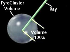
As you can see, the percent volume defines how clearly the raytracing ray will be seen within the PyroCluster body. This is the part of the ray within the body, which is affected by the percent volume. The length of this ray represents the distance (for samples). A Volume value of 50% would only use half the number of points in this body to create the fractal noise. Lower values result in faster render times but the smoke or cloud effect would look correspondingly worse.
Usually PyroCluster uses a weighted calculation algorithm to add the atmospheric effects to the scene. The particular calculation used means that, in general, dense clouds are rendered darker and more opaque than thin clouds.
This Luminosity setting gives you control over the amount of additive pixel calculation, expressed as a percentage of the total effect. This is the opposite of weighted pixel blending because, in this case, as you increase the Luminosity value more particles in an area result in a brighter overall appearance.
As you increase the value to 100%, Luminosity smoothly turns the calculation into an additive pixel color blend; pixel intensities will be added and you will get bright areas instead of dark ones in the cloud.
Take a look at the following example:
 Particles with Luminosity set to 0%
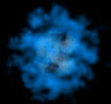
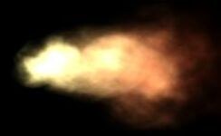 Particles with Luminosity set to 100%
This value controls the overall transparency of the atmospheric effect. A value of 0 means that every single puff will be 100% transparent. Higher values will make the volumetric effect more dense.
Keep in mind that low density values may have a huge impact on render time. The puff’s density is calculated according to several aspects of the effect. Each particle in the particle system generates a puff and each puff adds to the opacity of the overall effect.
You can imagine the Density value as a global transparency controller for the puffs. However, keep in mind that when you have just 100 particles with a high density, say 50%, you may well be able to see through this cloud. Increasing the particle count, while keeping them in the same-sized volume, would result in a denser cloud.
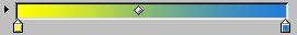
The Color gradient on the Globals page controls the color of the puffs.
The Color gradient controls the color of the puff. From left to right, the gradient represents the inside to the outside of the puff. This gradient provides the base colors for all calculations and must therefore be created and edited with some thought.
PyroCluster generally renders puffs based on the values in a color gradient. The color to the left of the gradient is used in the center of the puff while the color to the right is used at the outer edges.
Local Radius gradients (using the same gradient as in the Flat Radius example above) with Max set to 100 (left) and 50 (right). Note that there is more blue on the outer edges of the puff to the right because blue is used as the puff color from 50% of the radius to its full value
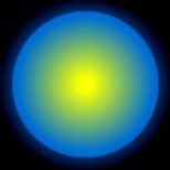
Local Radius mode always applies the color gradient within the volume of the puff, from the center to the surface of each puff. The color to the left of the gradient is used for the center of the puff while the color on the right is used at the edges.
It makes no difference how large the puff grows, since the gradient is always adjusted to fit, a process known as normalization. You can change the normalization of the gradient using the Min and Max values. Min represents the center area (0 is the actual center) and Max represents the outer edge of the puff (100% is equivalent to the radius of the puff). For example, a Max value of 80% means that the right-hand side of the gradient color will be used to draw the puff when the distance from the center is greater than 80% of the radius.
A maximum value of 80 will result in the color at the right of the gradient being used to depict the mass when the radius is greater than 80% of the entire radius. A value of 50% will result in the mass being depicted beginning at half the radius of the mass.
 Max. Radius = 100 Max. Radius = 100 | 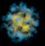 Max. Radius = 50 Max. Radius = 50 |
World Radius mode uses a non-normalized color gradient and the Min and Max values represent the radius measured in World coordinates. For example, suppose the puffs have a radius of 50, the Max value is set to 25 and the color gradient is yellow to blue: only the right-hand side color of the gradient (blue, in this case) will be used to draw the puffs at distances more than 25 units from the center.
Again using the same gradient as in the Flat Radius example above and a puff radius of 50, here are two examples of using World Radius gradients with Max set to 10 (left) and 25 (right).
 Max Radius = 10.0 Max Radius = 10.0 | 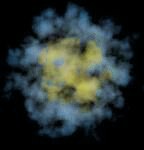 Max Radius = 25.0 Max Radius = 25.0 |
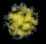
Use the Density mode to draw the puffs based on the individual density values of each point in the volume.
The left-hand color in the color gradient is used for areas of minimum (Min) density.
The right-hand color of the gradient is used for the areas of maximum (Max) density.
The right-hand color of the gradient is used for the areas of maximum (Max) density.
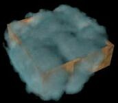
A wooden box filled with smoke, with Use Intersection disabled (left) and enabled (right). The enabled option keeps the smoke in the box.
Intersection tests are normally used to detect collisions in dynamic simulations. However, intersection testing also helps to constrain gas or smoke, so enable this option if you want to, for example, send a gas stream through a pipe. As you might expect, intersections can take quite some time to calculate for gaseous objects and a fast processor is recommended.
The Ray Bias value enables you to move the intersection point along the intersection ray to fine-tune the result. A value of 0 represents the originally calculated point of intersection; higher values will move the point away from there.
 Smoke escapes the box Smoke escapes the box | 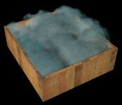 Smoke stays inside the box Smoke stays inside the box |
Six of the most commonly used effects are available as presets on the Settings drop-down list.
| Fire | 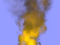 | Volcano | 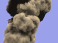 |
| Cloud | 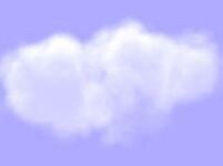 | Steam | 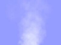 |
| FireBall | 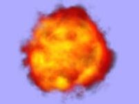 | Smoke | 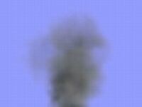 |