Particle Property Manager
The covered topics on this page are:
- Simulation Scene Selector
- System Properties
- Automatic Properties
- Manual Properties
- References
- Usage Example for Custom Properties
Simulation Scene Selector
You can configure the simulation settings via the Scene Settings (see the Simulation tab). There, you can specify the calculation precision and display quality, among other things. If your project contains multiple simulations that need to be calculated with different settings, you can also access Simulation Scene objects via the menu. These special objects provide their own simulation settings, which are then applied to the Simulation Objects that are arranged as child objects under the Simulation Scene object.
Particle properties for these separate Simulation Scenes can also be managed via the Particle Property Manager. To ensure it displays the correct properties, use this drop-down menu to select which simulation you want to edit:
-
No Simulation Scene: You can only manage particle properties if a Simulation Scene has been selected. If this has not yet been done, this option will appear. Even if there are no separate Simulation Scene Objects in the scene, you can always use the Default Simulation Scene, which is managed via the Scene Settings.
-
Default Simulation Scene: This entry is always present and refers to the Simulation settings, which can be accessed via Scene Settings. These settings are always used when there are no Simulation Scene objects in the scene and therefore apply to all simulation elements in your scene. But even when Simulation Scene objects are available in the scene, these default settings are still relevant, because they apply to all particles that are not managed by any of the existing Simulation Scenes.
-
Your Simulation Scene Object: If you have added custom Simulation Scene objects to the scene, you can select their names here. All settings in the Particle Property Manager will then apply only to the properties of the particle simulations managed by the corresponding Simulation Scene object.

Here you will find an option list of the most important properties of particles, such as their Color, Radius, Velocity or Alignment. Only the properties activated here are actually calculated and evaluated within the simulation. This also means that, for example, Conditions or Modifiers that access or influence these properties may no longer have any effect if the corresponding option in this list has been deactivated. The advantage of properties that are no longer used is that no memory needs to be reserved for them, which can be an advantage for simulations with a large number of particles.
If it is unavoidable for the function of a simulation at some points to have to calculate with a property switched off here, these default values are used as a substitute:
- Properties that are described by floating point values, such as Age, Radius or Distance Traversed, are interpreted with the value 0.
- Properties that can only be described by vectors, such as Velocities or Colors, are interpreted with the zero vector or the 4D vector (0,0,0,0).
- Properties based on quaternions, such as the Alignment of the particle axes, are set to the standard unit qu.
- Group links are automatically set to the root group. The particles are thus interpreted as groupless.
Note that there are also properties that are interdependent, such as Velocity and Distance Traversed. In this case, deactivating the Velocity automatically deactivates the calculation of the Distance Traversed.
The options can also be switched on and off while a simulation is running. When switching off, the corresponding memory area is released; when switching on, the memory area is reserved again and filled with the corresponding default values of the property.
In order to ensure that the particle system functions in every case, not all properties can be deactivated manually. The properties for the Position, the Unique ID of the particles and the Group are therefore always active.
This area lists the particle properties that were created directly via Particle Emitters or Particle Modifiers. For example, options can be activated on a Basic Emitter in its Output category to transfer the UVW Coordinates of the particles or a bool signal to a variable to indicate whether a particle has just been generated. This variable, called a Custom Property, can then be read out again in other Particle Modifiers or Particle Conditions and used to color or change other particle properties.
In the Output settings of many Particle Emitters and Modifiers, options for using Custom Properties can be found. Activation automatically leads to the entry of a name. However, this can also be changed manually if you want to use a different term for the corresponding value. In each case, the Custom Property that was automatically generated by activating an Output option on an emitter or modifier is listed in this area. These elements of the particle simulation are able to generate automatic custom properties:
- Basic Emitter (properties: Born, UVW Coordinates)
- Mesh Emitter (properties: Born, Point Index, Normal, UVW Coordinates)
- Reproduce Emitter (properties: Born, Source Particle ID)
- Spline Emitter (properties: Born, T Value, Segment T Value, Segment Index)
- Liquid Fill Emitter (property: Born)
- Switch Group Modifier (property: Previous Group)
- Flock Modifier (properties: Closest Particle ID, Neighbor Count)
- Predator Prey Modifier (properties: Predator Neighbor Count, Prey Neighbor Count, Chasing, Chasing Particle ID, Prey Distance, Caught Prey, Fleeing, Fleeing From Particle ID, Predator Distance, Was Caught)
- Collide Modifier (properties: Collided, Count Collisions, Collision Speed, UVW Coordinates, Surface Normal)
- Follow Spline Modifier (properties: Inside Effect Radius, Distance, Segment Index, T Value)
- Pyro Advect Modifier (properties: Density, Temperature)
- Stick Modifier (property: Is Stuck)
- Surface Attract Modifier (properties: Inside Effect Radius, Distance, Surface Normal, UVW Coordinates)
As can be seen on the left-hand side in the following illustration, a Basic Emitter, for example, offers various Output options for saving data from the generated particles in a property variable. This makes it possible to read out this particle property in other modifiers and thus, for example, to make the behavior of the particles dependent on this property.
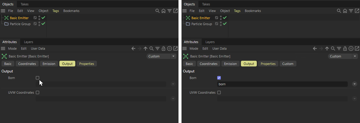 The activation of an output at a Basic Emitter and the custom property automatically generated and assigned as a result.
As the figure above shows, activating one of the desired Output options (see left side of the figure) leads to the automatic creation and entry of a custom property, in this case for the particle's Born property (see right side of the figure). In addition to a sensibly chosen name, the generated property is also given a suitable data type. In this case, Bool to indicate that a particle has just been created (value: true) or has existed for some time (value: false).
As the particles are generally independent of the emitter and are managed by separate Particle Groups, the emitter can only ever generate the true signal for the newly created particles. The special Event Bool data type therefore always automatically resets the value of this custom property to false. This way you can be sure that all particles are assigned the value false and only the newly created particles are assigned the value true by the Emitter.
As the right-hand side of the following illustration shows, you will find all automatically generated properties listed in the section for Automatic Properties. The columns offered there have the following meaning:
-
Used: This can be used to switch a property on or off. Emitters, conditions or modifiers that access a deactivated property can then no longer function and are deactivated. Where it is essential for the simulation to work with the values of a deactivated custom property, default values are used, as described here.
-
Name: The name of the property. You can also edit this default name here. If you have already read or overwritten this property (e.g., in Particle Modifiers) and then change its name here, you should first check the On Rename adjust References option. Only if this option is enabled will all references to this particle property be automatically updated. Otherwise, you would have to check the references yourself afterward and update them as needed.
-
Type: The assigned data types of the properties are displayed here. This data type is automatically assigned appropriately when you have an automatic particle property created. If you want to use your own data type, you can also create Manual Particle Properties. You can find out more about this in the description of the next section on manually created custom properties.
-
Remove: If you find that you have created a Particle Property but no longer need it in your simulation, you can remove it using the Remove button. Please note the On Remove clear References option. Only when this option is enabled will references to this property be automatically removed from all Emitters, Conditions, Groups, and Modifiers, for example.
This option ensures that even if a property is renamed later via the Name field, all references to that property in other simulation objects are automatically updated. This allows you to continue reading and overwriting values for this property without interruption. Otherwise, if a used property is renamed later, you may need to manually update all entries in Emitters, Conditions, or Modifiers that access that property.
This option ensures that when a particle property is removed (using the Remove button), all references to that property are automatically removed from the particle simulation objects as well. A pop-up dialog box shows which objects the references were removed from.
To keep track of which properties are read, overwritten, or otherwise output within the simulation at any given time, you can find a complete list under References. This section is also shown in the figure below.
There are four columns available there:
-
Info: The Names and data types of all active Particle Properties of the chosen Simulation Scene are listed here.
This also includes properties that are processed by default—for example, on Modifiers—without requiring manual activation. -
Output: In this column, all properties that have been enabled via the Output page—for example, of a Particle Emitter or Modifier—are marked with a drop-down menu. In our example, for instance, the Born property was enabled on a Base Emitter. Accordingly, in the Output column, next to the entry for born [Event Bool], we can also find a drop-down menu listing the Basic Emitter. These drop-down menus not only indicate where a property is being used but also allow you to select the corresponding object directly, thereby displaying its settings in the Attribute Manager.
-
Read: The drop-down menus in this column list all the particle simulation objects for which the corresponding property can be read.
-
Modified: The drop-down menus in this column list all the particle simulation objects for which the corresponding property can be or actually are modified.
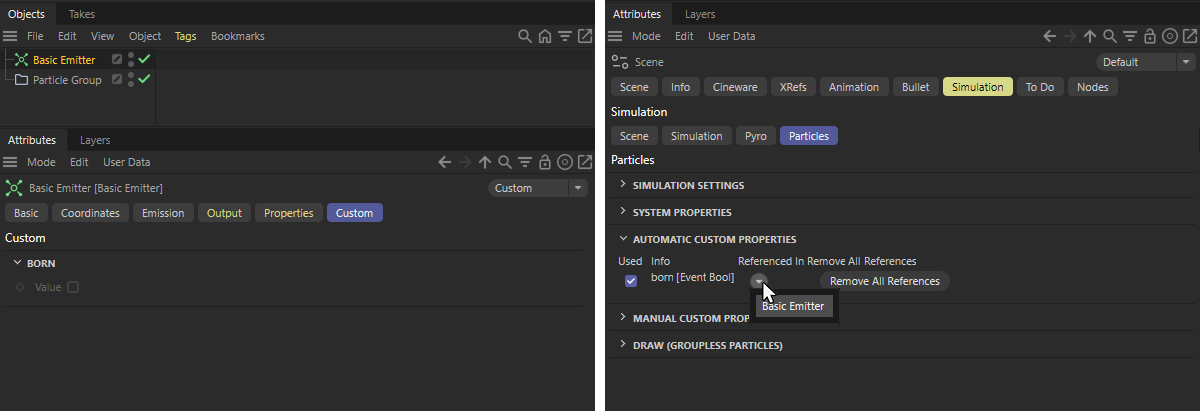 Activating an output, e.g. at a Basic Emitter, automatically generates a custom property, which is listed in the Automatic Properties section of the Particle Property Manager. In the lower part of that Manager you can also keep track about where each property is used in your Simulation Scene. The values of the custom properties used can be viewed in the Custom section of the particle simulation object. This can be seen on the left of the picture. For manually created properties, start values can then also be assigned there.
You will find examples of how to use the custom property data, e.g. in the introductory chapter on particle simulation or in the section on Manual Custom Properties directly below.
When using particles defined as liquid in the scene, additional particles properties are automatically activated and can be read out and, in some cases, changed using the same Conditions and Modifiers known from the particle system. However, these properties are not listed here again, but are directly available if you select the CustomProperty in particle modifiers, for example.
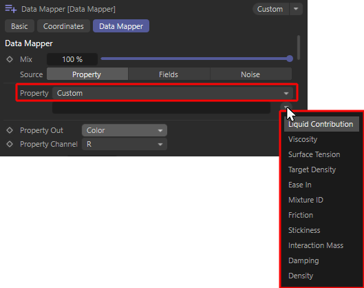 When using liquid particles, their most important properties are automatically available as custom properties (demonstrated here using the example of a Data Mapper Modifier). The "References" section of the Particle Property Manager also lists these additional liquid particle properties with their data types (see right side of the figure)
These special properties can be used to change a liquid over time, for example, or to keep it dependent on other properties of the simulation. Liquid particles can be generated directly with a Liquid Fill Emitter or by converting standard particles with a Liquify Modifier. Please note that many of the particle properties listed below can also be changed directly at any time using a Liquify Modifier.
These properties are automatically available for this purpose:
-
Liquid Contribution [Float]; This value is between 0 and 1 and indicates whether a particle only has to adhere to the forces, conditions and modifiers of the particle simulation (value = 0) or whether it is a liquid particle (value = 1) for which additional forces, such as gravity and forces between neighboring liquid particles, apply. By changing this value, particles can therefore switch continuously between the properties of "normal" particles and the properties of liquid particles.
-
Viscosity [Float]: This value describes the flow resistance of the liquid. Low values make a liquid appear watery and thin, higher values make it appear viscous and like honey.
-
Surface Tension [Float]: This describes the surface tension of the liquid. As the values increase, the liquid particles tend to clump together more. This can be used to obtain larger individual drops, for example. It should be noted that this property also depends on the particle density present (Target Density).
-
Target Density [Float]: This describes the particle density per unit volume that the simulation should achieve as far as possible for the liquid particles. A higher density per volume has an effect in combination with other dynamic simulation objects, among other things. A liquid with a higher density can then exert a stronger force on items of clothing or rigid body objects, for example.
In addition, the forces acting between the liquid particles also depend on this density. If more particles are drawn together in the same space, the Surface Tension can also show stronger effects. -
Ease In [Float - Time]: This value specified in simulation images describes the time span required by the particles to change from normal particle properties, which are influenced e.g. via the emitter properties or particle modifiers and force objects, to characteristic fluid properties. Since pure liquid particles, for example, can react extremely to overlapping of their radii during formation at the emitter, this transition time can be used to mitigate extreme repulsion of colliding liquid particles at the emitter.
-
Mixture [Index]: All particles that have the same Mixture ID value are simulated as one liquid. Liquid particles with different Mixture ID values can no longer be mixed freely and therefore remain separate from each other within the simulation, even if, for example, their Target Density settings are identical.
-
Friction [Float]: This value relates to the interaction of the liquid with other objects that have a Collider Tag or have been defined as Cloth or Rigid Body, for example. The value then describes the energy loss due to friction that the liquid suffers during contact with the collision object. Please note that the actual friction and the actual energy loss are also influenced by the Friction value on the Collider Tag or on the dynamic object. The friction of the liquid is only taken into account if the colliding object also has friction.
-
Stickiness [Float]: This value relates to the interaction of the liquid with collision objects, e.g. objects that have a Collider Tag. The value then describes the adhesion and adherence of the liquid to the collision object. Please note that the sticking is also influenced by the Stickiness value, e.g. on the Collider Tag. Only if the colliding object also has Stickiness values above 0 is the Stickiness of the liquid taken into account.
-
Interaction Mass [Float]: This value indicates the mass of the liquid particles. The mass plays a role above all in the interaction with other dynamic simulation objects, because together with the speed of the particles, this results in the force that the particles can exert. Particles with a greater mass can, for example, deform simulated materials more strongly or move rigid bodies more easily.
-
Damping [Float]: This percentage value describes the energy loss within the fluid simulation. The greater the damping, the slower the liquid particles move and the faster strong accelerations are reduced. Damping can therefore prevent the simulation from 'exploding', but if the values are too high, it also leads to a strongly decelerated and unnatural behavior of the liquids, which in extreme cases can freeze completely.
-
Density [Float]: This value is only intended for the output and can therefore not be written to the liquid particles. This is the current density of the liquid in the vicinity of the respective particle. For particles in the core area of a liquid, this value should therefore be relatively close to the desired Target Density.
The effect of these properties on the liquid simulation can be read in the description of the Liquid Fill Emitter, among other things.
| Here, some properties of the liquid particles, such as their Color, Density, Viscosity and Surface Tension, are changed during the simulation by modifiers depending on the Age of the particles. |

|
In addition to the predefined properties—which can be enabled directly, for example, via the Output settings on emitters or certain modifiers—you can also create your own custom property variables and link them to the particles. This allows you to incorporate values you’ve calculated yourself into the simulation.
There is no need for a direct link between the properties used manually and the actual properties of the particles. They can be used completely independently.
Particles can also be given their own additional values via this Add Custom Property button, which can be read or written by these emitters, modifiers and conditions:
- Basic Emitter (write only)
- Mesh Emitter (write only)
- Reproduce Emitter (write only)
- Spline Emitter (write only)
- Condition (read only)
- Color Mapper Modifier (read and write)
- Data Mapper Modifier (read and write)
- Math Modifier (read and write)
- Switch Group Modifier (write only)
- Look Modifier (write only)
- Blend Modifier (read and write)
- Flock Modifier (write only)
- Predator Prey Modifier (write only)
- Collide Modifier (write only)
- Follow Spline Modifier (write only)
- Pyro Advect Modifier (write only)
- Stick Modifier (writing only)
- Surface Attract Modifier (write only)
- Particle Node Modifier (read only)
Unlike the Automatically created custom properties, with these Manually created properties you have full control over which data type they should use. These properties are therefore well suited for mathematical calculations or special data types, such as colors with alpha, which are not directly offered by the automatically generated properties.
It should always be ensured that the respective data type is as compatible as possible with the selected operation or function of the respective modifier or condition. A property defined as a particle Group Link can therefore, for example, only be read out within a Condition and compared there with another Particle Group, for example.
Other properties based on floating point values, on the other hand, can be used in a more versatile way and can be interpreted, for example, as Radius, Velocity Speed or Age.
The same applies to vectors, which can be used to describe a Color, the Velocity direction or a Position, for example.
However, it is also the case with Node circuits that attempts are made to convert different data types in a meaningful way when exchanging data. This means that integer values can also become floating point values or, for example, a vector. Depending on the type of conversion, however, this can also result in value changes, e.g., when a floating point value is converted to a bool value or a vector is converted to an integer number. It therefore generally makes sense to select the data type so that it corresponds to the values that you want to manage with this custom property.
When creating a new particle property, various setting options appear, as shown in the following illustration:
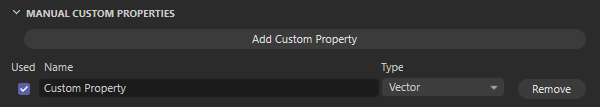 The settings for manual, custom particle properties
Additional custom properties can be added at any time using the Add Custom Property button, which can then be used by the Emitters, Conditions and Modifiersmentioned above.
In the left-hand column you will find a Used option to switch the respective custom property on or off. Particle Conditions or Modifiers that access a deactivated property can then no longer function and are deactivated. Where it is essential for the simulation to work with the values of a deactivated custom property, default values are used, as described here.
The Name text field in the adjacent column contains the name of the property. You can enter this yourself here. Note, however, that some property names are already in use, such as Color, Radius or Position. These names can therefore not be used again. Please also note that if there are already entries in the list of Automatic Custom Properties, you should not use any names that are already used there. Always try to find unique names.
The name of a Custom Property can also be changed anytime later if necessary. The capitalization of a name is irrelevant for subsequent use. However, when subsequently changing property names, take care to have On Rename adjust References active, so that connected simulation objects get updated automatically.
Use the Type menu to select the data type for your custom property. The following data types are available and must be selected to match the values that you want to save and process with the corresponding property. The values transferred to the user properties from the particle system are not converted and therefore always expect the data type with which this data is also used within the particle system.
-
Integer: This can only be used to manage integer values, such as those used to count collisions on a Collide Modifier.
-
Index: Each particle can be identified by an integer number, the so-called ID or Index. This data type is specifically intended for storing this information, as negative values are not possible here, for example.
-
Bool: This data type only knows two states, true(i.e. on, or 1) and false (i.e. off, or 0). This makes it possible, for example, to save whether a particle has just been born or should be deleted. For example, the Basic Emitter allows you to save the Born status of the particles in a user property that uses this Boole data type. Please note, however, that the special Event Bool data type is also available for such events with a short time limit. This has the advantage of automatically returning to the value false. This ensures that a true value is only ever present for the exact point in time at which an event takes place (such as a collision or the birth of a new particle).
-
Group linking: This can be used to save particle groups. For example, the Switch Group modifier offers an option to save the previous group of a particle in this data type before changing it. A Condition can be used to read a group link.
-
Float: This is a floating point value without a unit and can be used, for example, to save a color component or whenever only a pure numerical value is to be saved.
-
Float - Meters: This floating point number can represent a Radius or a Distance Traversed, for example, and is automatically displayed with a distance unit such as meters, centimeters or inches, depending on your Units defined from the C4D Preferences. Because a distance unit is included, this value is also subject to automatic adjustment by the Project Scale, for example.
-
Float - Degree: This floating point number is used to store an angle.
-
Float - Time: This floating point number is intended for storing times and time intervals, such as the Age or Lifetime properties.
-
Float - Percentage: This floating point value is intended for storing percentage values, such as the Age Percentage property.
-
Vector: This is a 3D vector without a unit. These can be UVW coordinates or RGB color values, for example. The individual components of the vector consist of float values.
-
Vector - Meter: This is a 3D vector with a distance unit that can be used, for example, to transmit Positions or Velocities. Because a distance unit is included, this value is also subject to automatic adjustment by the Project Scale, for example. The individual components of the vector consist of float values.
-
Color A: This is a 4D vector format that can be used to manage the RGB color values and the alpha value. All components of this vector therefore consist of float values.
-
Quaternion: This special format is only suitable for storing the Alignment of a particle.
The following data types already have an automatic reset or increment built in:
-
Event Bool: This is the familiar Bool data type, which can be used to manage exactly two states, namely true and false. This can be used for unambiguous events, such as the identification of a colliding particle. However, unlike the Bool data type already presented, the value is always automatically reset to false with Event Bool. For this reason, this data type is also automatically used for the Born properties on the emitters, for example. The value can then only be set to true for the new particles generated at the emitter at that moment and is then automatically reset to false in the next calculation step of the simulation.
-
Timer: This is a Float data type, which is intended for recording time intervals. The value of this customproperty is automatically increased by the amount of time that has passed since the simulation was last calculated. If, for example, you reset this property to the value 0 via the evaluation of a Particle Condition, subsequent modifiers and conditions can read out how much time has passed since the reset by accessing this custom property.
-
Substep Counter: This corresponds to the Integer data type, except that the value is increased automatically. The value of this property increases by 1 with each iteration of the simulation calculation. As with Timer, you can create a basis at any time by setting the value 0 in order to be able to evaluate the number of calculation cycles within the simulation since this reset.
On the various emitter objects (Basic Emitter, Spline Emitter, Mesh Emitter and Reproduce) you will find a list of all custom properties created with corresponding color or value fields in their Custom category. You can also assign individual start values to all properties so that, for example, a color property directly receives the desired color value. All subsequent conditions and modifiers can then continue to work directly with these initial values of the properties. This also ensures that all custom properties are always defined and contain a value.
Finally, the Remove button also allows you to delete a custom property that is no longer required. However, all Conditions and Modifiers that used this property will then no longer work and must be reconfigured. To temporarily deactivate individual properties, you can also deactivate the corresponding Used options instead.
If you decide to delete a custom property that is already used, for example, by modifiers, this option ensures that all entries for that property are removed at the same time.
Note that all Custom Properties for the particles are always managed by the chosen Simulation Scene of your simulation (see setting at the very top of the Particle Property Manager).
The Custom Particle Properties can also be used directly as maps, e.g. to control colors or the emission on a Pyro Emitter Tag.
Here you will find explanations and examples.
This option ensures that even if a property is renamed later via the Name field, all references to that property in other simulation objects are automatically updated. This allows you to continue reading and overwriting values for this property without interruption. Otherwise, if a used property is renamed later, you may need to manually update all entries in Emitters, Conditions, or Modifiers that access that property.
This option ensures that when a particle property is removed (using the Remove button), all references to that property are automatically removed from the particle simulation objects as well. A pop-up dialog box shows which objects the references were removed from.
To keep track of which properties are read, overwritten, or otherwise output within the simulation at any given time, you can find this list.
There are four columns available there:
-
Info: The Names and data types of all active Particle Properties of the chosen Simulation Scene are listed here.
This also includes properties that are processed by default—for example, on Modifiers—without requiring manual activation. -
Output: In this column, all properties that have been enabled via the Output page—for example, of a Particle Emitter or Modifier—are marked with a drop-down menu. When you select an object from these drop-down menus, it will be selected, and you can then access its settings directly through the Attribute Manager.
-
Read: The drop-down menus in this column list all the particle simulation objects for which the corresponding property can be read. When you select an object from these drop-down menus, it will be selected, and you can then access its settings directly through the Attribute Manager.
-
Modified: The drop-down menus in this column list all the particle simulation objects for which the corresponding property can be or actually are modified. When you select an object from these drop-down menus, it will be selected, and you can then access its settings directly through the Attribute Manager.
Usage Example for Custom Properties
Some emitters and modifiers already offer a selection of particle properties that can be passed directly to Custom Properties. For example, you will find an option to write the UVW Coordinates of the used emitter shape in the Output tab on the Basic Emitter. Let's use this information to color the particles.
To do this, activate the option for the UVW Coordinates in the Output tab of the Basic Emitter. As a result, a custom property is automatically created with the name uvw, for which the Vector data type is used.
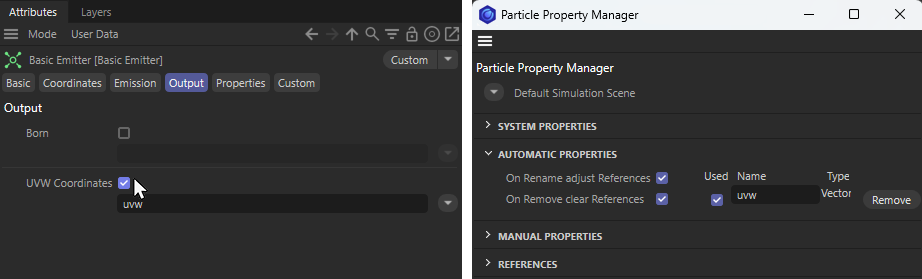 Enabling UVW Coordinates output on a Basic Emitter automatically creates a particle property named “uvw,” which is also displayed in the Particle Property Manager (see the right side of the figure).
Alternatively, you can also first define your own variable as a Manual Property in the Particle Property Manager and then select this new property via the drop-down menu behind the name field of the UVW Coordinates property on the emitter. You just need to make sure that the data type of the custom property matches the Particle property that is to be carried within it.
In this example we use EmitterUVW as the new Name and select Vector as the Type, as we are dealing with three values without a unit for the UVW coordinates.
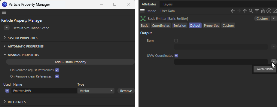 The left side shows how to create a new Custom Property named "EmitterUVW" with the data type "Vector". The right side of the figure shows how this property is then selected to output the UVW Coordinates of the Basic Emitter.
Let us now turn our attention back to the Basic Emitter. Activate the Cube as the emitter shape, for example, in order to obtain U, V and W components. With 2D emitter shapes, the W component would otherwise always be 0.
From now on, the emitter will automatically write the UVW coordinates of each newly created particle to either the automatically created uvw property or the manually created EmitterUVW custom property. In this example, we decide on the EmitterUVW property, which we can now read out with Math Modifiers, for example, and pass to any other property of the particle, such as the color of the particle. The following figure illustrates this.
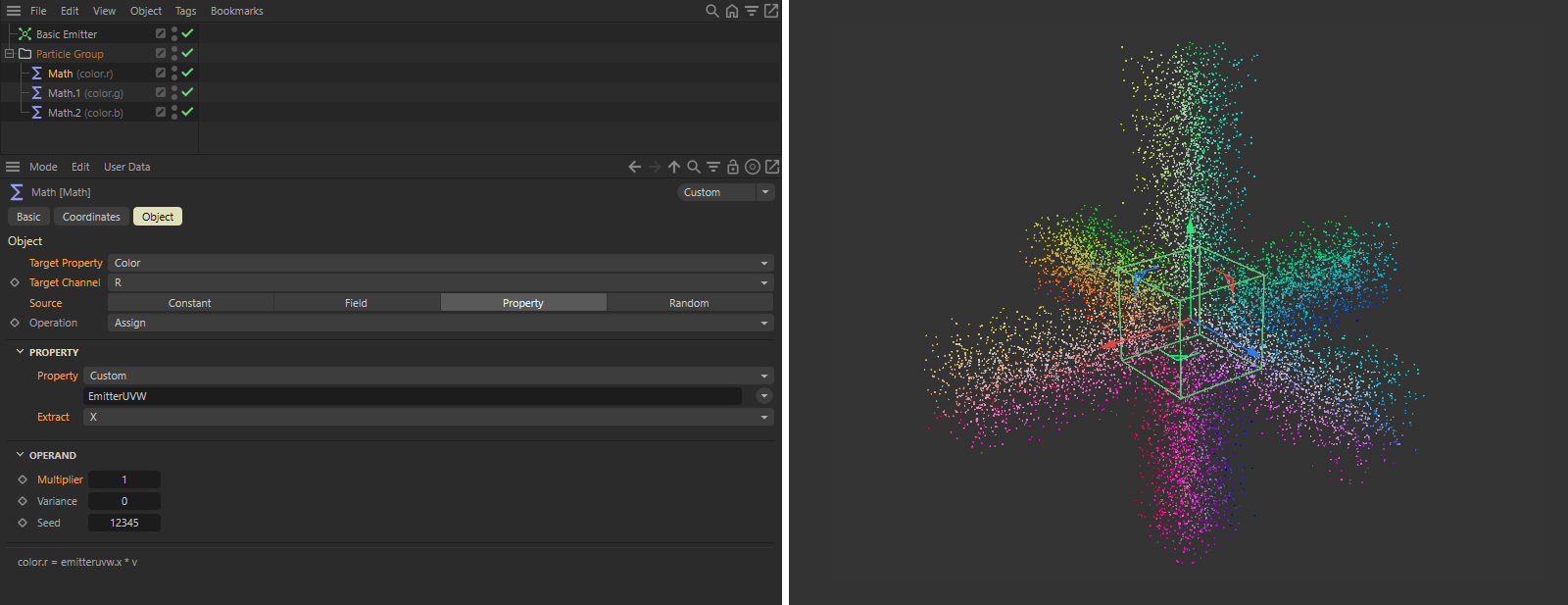 Transfer of the stored UVW coordinates to the color property of the particles.
Using three Math modifiers, we transfer the stored U, V and W components (since the UVW values were stored as a vector, these can be extracted from the X, Y and Z components of the vector) to the R, G and B components of the particle colors. Also pay attention to the Multiplier of the Math Modifiers. To convert UVW coordinates directly to RGB values, this Multiplier should be set to 1. The right half of the figure above shows the result.