
Scratches
Overview
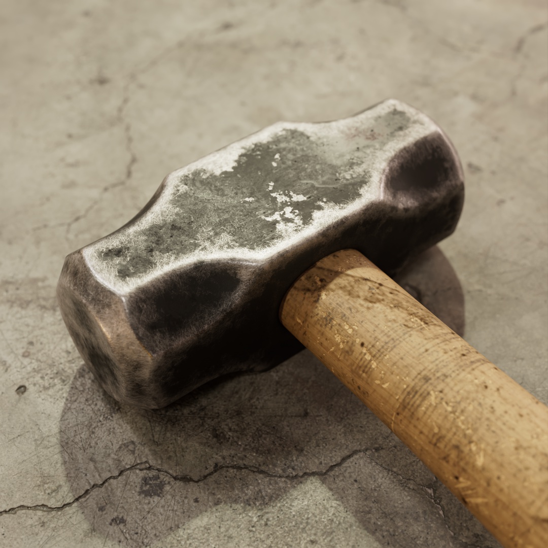
|
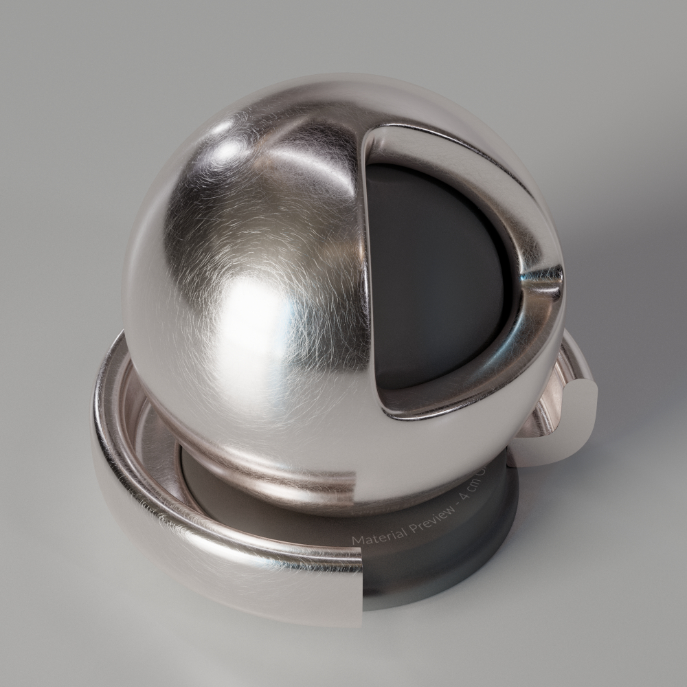
|
The Scratches shader is great for procedurally adding realistic surface wear to materials without the need for external textures. It's great for making metals, paints, plastics, glass, and any material with a coat layer look more authentic by adding random scratch marks on the surface. It offers lots of flexible looks and variation for scratch length and width, curvature, masking, and the ability to bias scratches along a particular direction - making it great for brushed metals. Normally, setting up a complex effect up like this can be time consuming, requiring many textures and parameter tweaks throughout a shader graph. The Scratches shader makes this plug and play and puts all the controls in one place.
Examples
In this section two materials are created and used together, a brushed metal is used for metallic door hardware that is scratched away to reveal a silver material beneath the surface. Each section touches on different aspects of setting up and using the Scratches shader.
Connecting a Scratches shader
To start with we need to get our scratches hooked up to a material. A simple setup usually requires the connection of 4 ports.
outBump should be plugged directly into the Material's Bump Map port, no need for a Bump Map node.
| Output | Input - OpenPBR | Input - Standard Material |
| outRoughness | Specular - Roughness | Reflection - Roughness |
| outAnisotropy | Specular - Anisotropy | Reflection - Anisotropy |
| outAnisotropyRotation | N/A | Reflection - Rotation |
| outAnisotropyTangent | Specular - Anisotropy Tangent | N/A |
| outBump | Geometry - Bump Map | Geometry - Bump Map |
What about Base material textures?
Since the scratches shader connects to several important ports on a material you may be wondering what to do with your roughness textures. These can be layered like usual with things like a color layer or mix node, but the Scratches shader also offers texturable inputs for the Base Specular Roughness, Base Specular Anisotropy, and Base Specular Rotation. These will pass the base specular data through the Scratch shaders relevant output ports along with the added information for the scratches themselves.
To layer a base material's bump map texture with the scratch output, use a Bump Blender. Just remember, the scratch shader does not need a bump map node itself. Scratches - outBump can be connected directly to a Bump Blender's input.
Scratch direction
Next we'll create the brushed metal base material, this is a critical part to get right because it relies on the scratches laying in a particular direction in order to achieve the right look. This is managed by adjusting the Scratch Direction and carefully orienting the UV unwrap of the model so that the scratches go the right way.
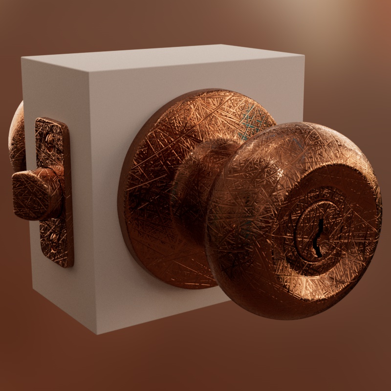
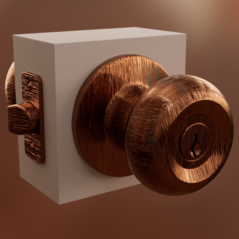
By default the Scratch Direction is set to 0 steps, resulting in scratches headed in completely random directions, making it great for quickly adding scratch wear and tear to most objects. However for brushed metal we need the scratches to go in very specific uniform directions, increasing the Steps to 1 gives us just that.
|
|
| Steps: 0 Coord. Space: Object |
1 Object |
This doesn't look quite right for brushed metal though, the scratches should be going around the door knob but right now it crisscrosses across the surface. This is because we are using Object for the Coordinate Space which uses a tri-planar projection to generate the scratches along the surface. Great for many objects but for this model we're going to need to spend some more time and attention on the unwrap of our model because we should be using the UV Coordinate Space instead.
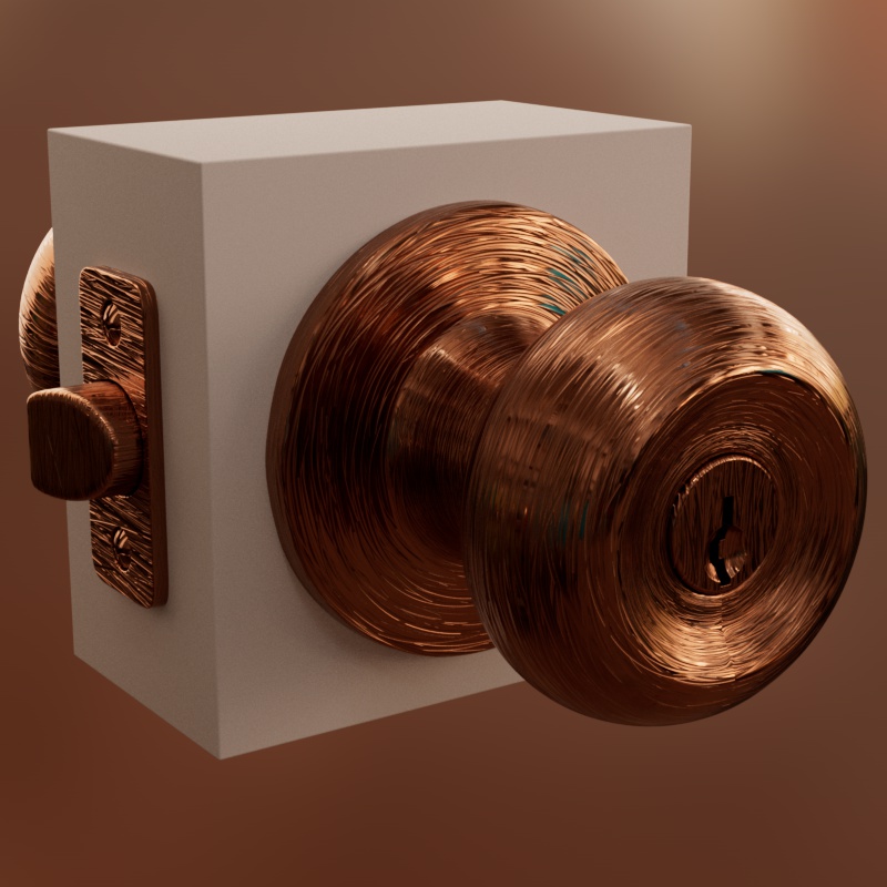
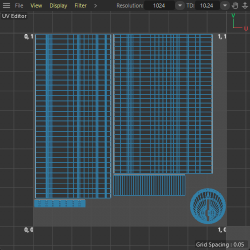
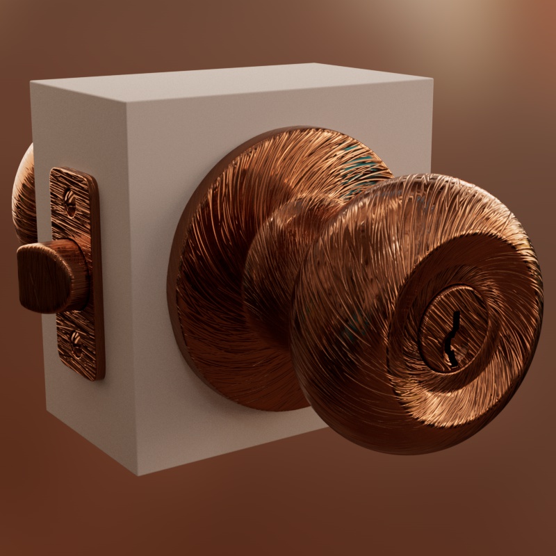
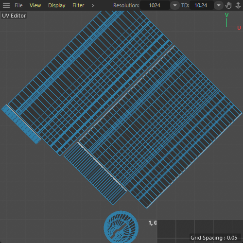
When using the UV mode, the orientation of the UV islands has a direct impact on the orientation and size of the scratches. The model has been unwrapped and the UV islands are carefully aligned to produce the correct scratch direction. In the second set of examples, you can see that when the UV islands are rotated 45 degrees the scratches rotate as well.
|
|
|
|
| Aligned UVs Coord. Space: UV Steps: 1 |
Aligned UVs | Rotated UVs | Rotated UVs |
Scratch sizing
Now that the scratches are all oriented in the correct direction we should make sure they have the right size so they can look their best, for brushed metal very thin scratches are needed for the right look. You can change the scratch length and width by adjusting the Scratch Canvas Size, this parameter uses scene units to control the size of the scratches.
When the Scratch Length and Width = 100 then the scratches will be as long and as wide as the Scratch Canvas Size. When using the same value for both this results in a circular scratch that's as wide as it is long, but generally you will want to keep the width value much lower - like a value of 1 which is equivalent to 1% of the Scratch Canvas Size.
When using the UV Coord. Space there's an extra parameter that you need to pay attention to. UV Canvas Size tells Redshift how wide, in scene units, the 0-1 space of your model's UV set is supposed to be. UV Canvas Size needs to be set correctly in order for the Scratch Canvas Size to be accurate and for best results your unwrap should use the same texel density for all UVs.
To set the UV Canvas Size properly you have to figure out how the scale of your UVs relate to the width of the 0-1 UV space and compare that to the actual size of the object in the scene. For this example we're going to find a visual landmark in the UV unwrap, the lock cylinder circled in red, and reference that in the 3D viewport. It turns out the lock cylinder is just about 2cm in diameter and since it takes up 2/10ths of the UV width we can determine that an accurate UV Canvas Size for this model and unwrap is 10cm.
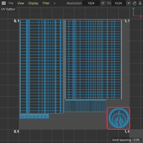
|
| Finding a UV landmark to reference in the scene |
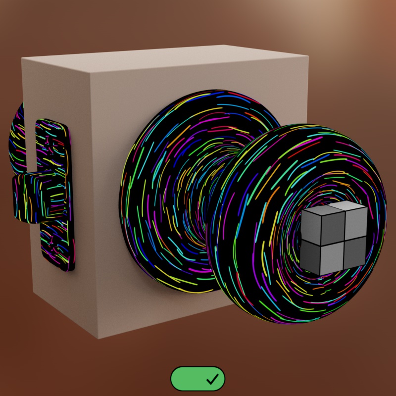
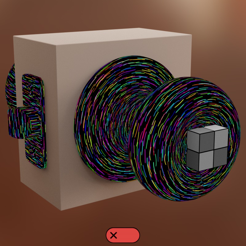
In the example below, the grey box is 2cm x 2cm in size and it fits right over the lock cylinder. When the UV Canvas Size is set properly (10cm) then the Scratch Canvas Size (2cm) is able to accurately portray scratches 2cm in length (example on the left). When it's not set properly the scratch size will not be accurate, in the second example they are twice as small since the UV Canvas Size is twice as big (20cm) as it should be.
|
|
| UV Canvas Size: 10cm Scratch Canvas Size: 2cm Accurate sizing |
UV Canvas Size: 20cm Scratch Canvas Size: 2cm Inaccurate sizing |
Now that we have the size figured out, the Scratch Canvas Size can be set to 10cm and the Scratch Length to 100 for some long 10cm scratches. Conversely, a very low Scratch Width of 0.5 is used for extremely thin scratches that are less than a millimeter thick (0.5% of 10cm).
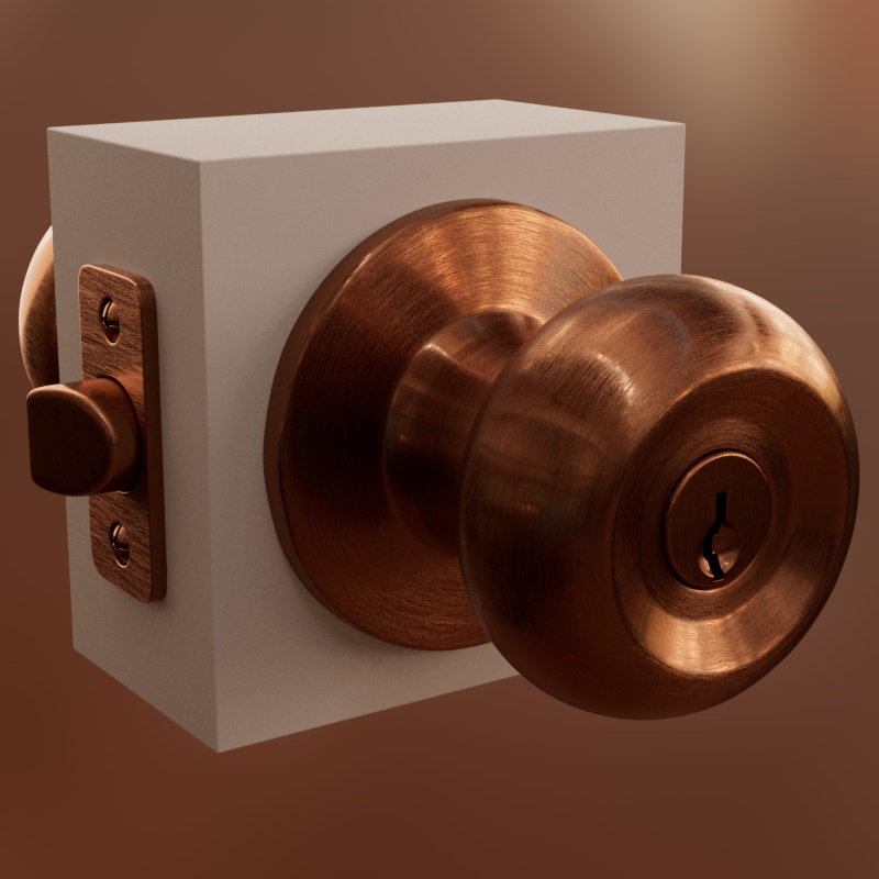
In the examples below, the only thing that has changed is the Scratch Canvas Size, everything else is identical - scale is very important with scratches. Random Length and Width are also used for variation and this results in a nice looking brushed metal.
|
|
|
| Scratch Canvas Size: 100cm | Scratch Canvas Size: 10cm |
Scratch masking
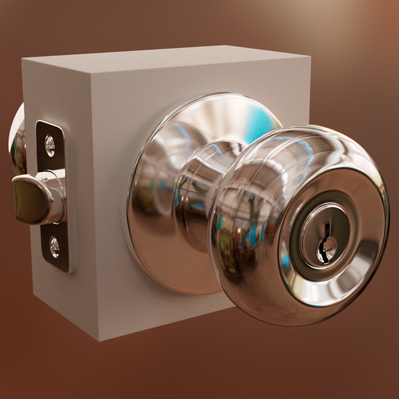
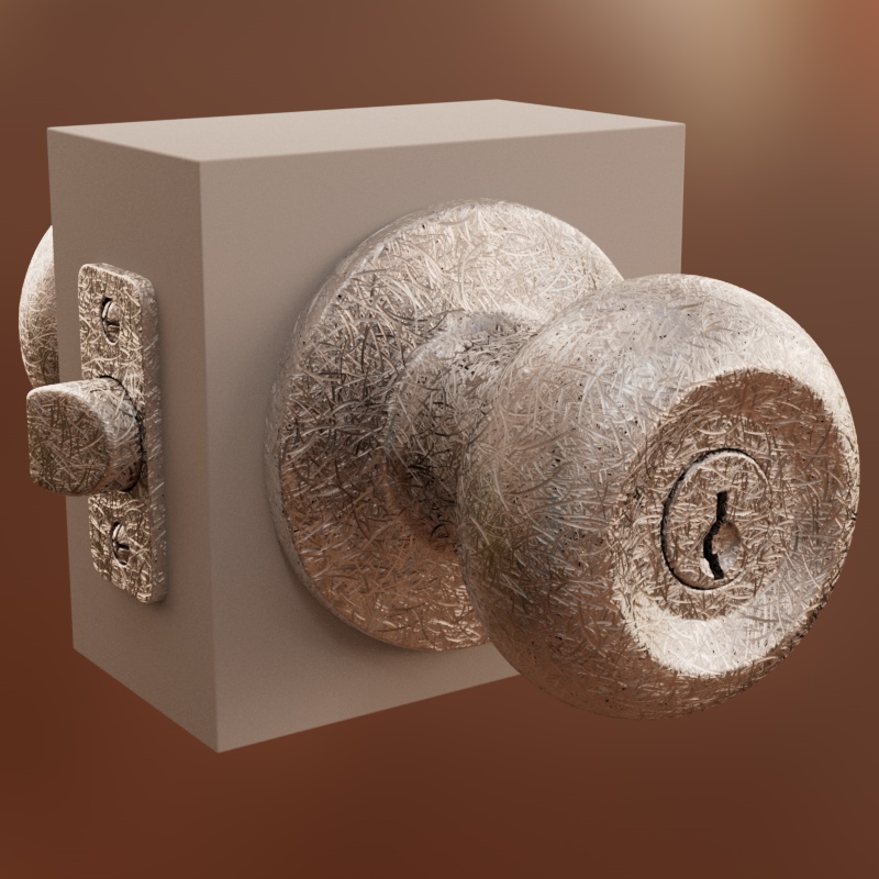
Now that the brushed metal has been established we can add some wear and tear. Create a new silver metallic material and connect a new scratches shader to it. For this material we don't need to worry about scratch orientation, the random direction of the scratches is perfect for the everyday wear and tear that an object might face.
|
|
| Silver metal with no scratches | Silver metal with random scratches |
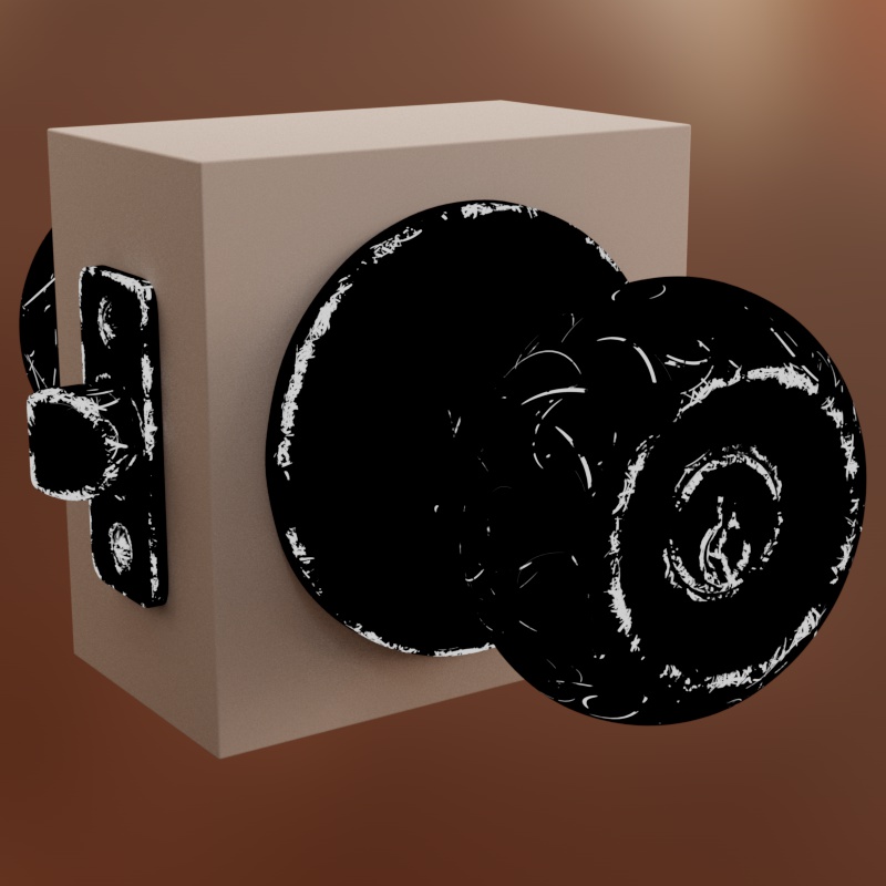
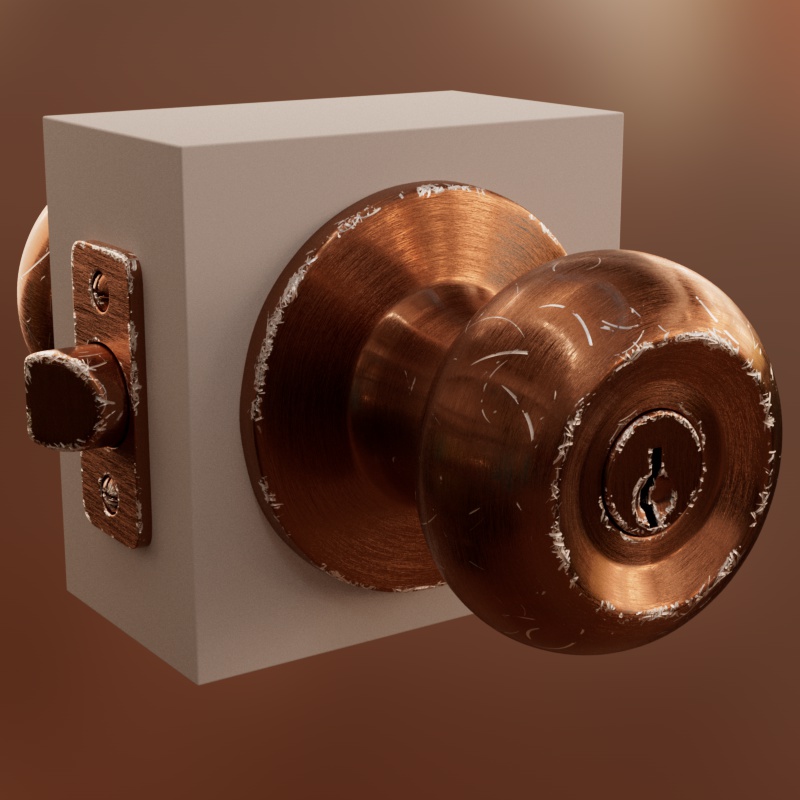
This time we don't want the scratches to cover the entire surface so the Mask input is used. A Curvature shader is great for this, it can restrict the scratches to the convex parts of the model, making scratches appear only on the edges of the object. The outScratchMask provides an output for separating areas with scratches (white) to the base layer with no scratches (black), this can be used for layering the silver scratches over the brushed metal layer.
|
|
| outScratchMask - Mask driven by curvature | Layered with outScratchMask |
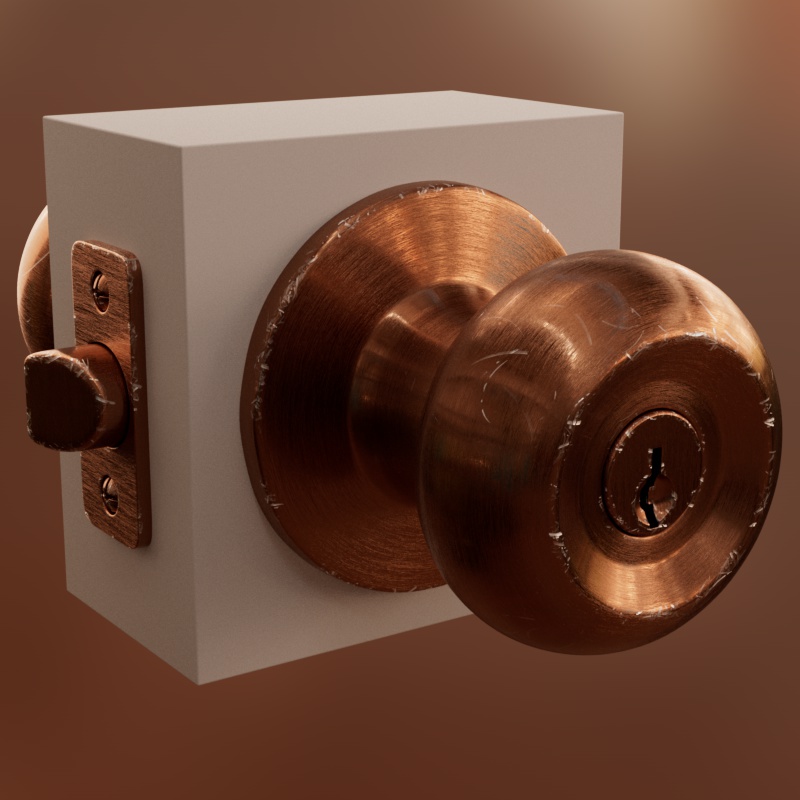
For added variation in the layer mask, you could instead use the multicolored outScratchColor and remap it to a black and white gradient ramp giving you a mask with more visual interest.
|
|
| outScratchColor | Improved mask variation |
Parameters
General Properties
Coord. Space
The coordinate space used to calculate the position and size of the scratches.
-
Object: The position and size of the scratches are relative to each object they are applied to.
-
World: The position and size of the scratches are relative to the world space. This will result in a consistent scratch size across all objects however the scratches will swim if the objects are moved through the scene.
-
UV: An object's UVs are used to determine the position and size of the scratches, the scale and orientation of the UVs has a direct impact on the size and position of the scratches.
|
Coord. Space: Object Physical Size: Enabled |
World N/A |
UV N/A |
Physical Size
Only available when using Coord. Space: Object
When enabled, the scale of the object the material is applied to is not factored into the scratch size. This is helpful when accurate sizing is most important, allowing you to rescale the object while maintaining accurate scratch sizing. Note, the scratches will swim when the object is scaled in order to retain the physical size.
When disabled, the scale of the object the material is applied to is multiplied with the scratch size. This keeps the scratches from swimming but they are stretched or squished when the object is scaled, meaning the physically accurate sizing is lost when at a scale other than 1,1,1.
| Physical Size: Enabled | Disabled |
Triplanar Blend Curve
Only available when using Coord. Space: World, Object
When using World or Object as the coordinate space the scratches are applied using triplanar projection. This controls the power curve of the triplanar axis blend transition. Higher values tighten the blend while lower values soften it. A value of 1 results in a linear blend.
| Triplanar Blend Curve: 1 - 10 |
UV Channel
Only available when using Coord. Space: UV
Specifies a UV set using the "UV Channel" field. By default, when the path is left blank, the default UV set used by the DCC is used automatically.
UV Context
Only available when using Coord. Space: UV
Connect a UV Context Projection node here to enable a local connection for simplified texture mapping. For more information, please see the UV Context Projection page.
UV Canvas Size
Only available when using Coord. Space: UV
Specifies the size of a UV tile in scene units. When accurate scratch sizing is desired this parameter is very important, if the UV Canvas Size is not accurate to the size of the object then the Scratch Canvas Size will not be accurate.
If you are using UV mode, you should create a unique material for each object that has a different UV Canvas Size, otherwise the scratches won't be accurately sized.
| UV Canvas Size: 1 - 50 |
Scratch Canvas Size
Specifies the length of a scratch in scene units when Scratch Length = 100. This is important when physically accurate scratch sizing is desired but if you are just going off the look of your scratches it also serves as an overall resizing control.
| Scratch Canvas Size: 1 - 10 |
Density
Controls how densely packed the scratches are across the surface. Higher values generate more scratches and cover more of the surface, while lower values generate fewer scratches and reveal more of the underlying unscratched surface.
Anywhere a scratch does not appear can be considered the material's base layer underneath, this is the area the Base Specular properties control and the part of the outScratchMask that is black.
When adjusting the density the scratches will move, this is done in order to maintain a consistent density relative to the scratch length.
| Density: 0 - 1.5 |
Mask
The mask can be used to control where scratches appear, low values (black) remove scratches while high values (white) retain scratches.
This input can be textured to keep scratches in some areas and remove them in others, like using a curvature shader to add scratches to the edge of an object.
| Mask: 0 - 1 |
Seed
Changes the seed which randomizes the scratch position, roughness, curvature, size, and other various elements.
| Changing the Seed |
Bump Strength
Controls the strength and direction of the scratch bump mapping effect. Positive values (default 1) makes the scratches behave as normal, like grooves that cut through the surface. Negative values make the scratches behave like bumps, inverting the light interaction. A value of 0 disables the bump effect completely.
| Bump Strength: -1 to +1 |
Scratch Shape
Length
Controls the length of the scratches. The length value functions as a percentage of the Scratch Canvas Size, at 100 a scratch will be exactly as long as the Scratch Canvas Size, at 50 it will be half as long, etc.
When using Random Length, this serves as the median length that the randomization is based on.
When adjusting length the scratches will move, this is done to preserve the overall density. Without this, increasing the length of the scratches would also increase the visual density since scratches would stretch out and fill the negative space.
| Length: 10 - 100 |
Random Length
Adds variation to the length of the scratches. Higher values result in more randomization, while a value of 0 results in no randomization and all scratches are exactly the same length.
The Random Length functions as a percentage of the length of a scratch to determine the total amount of randomization. For example, when Scratch Canvas Size is 10 units and the Length is 100 (10 unit long scratches) then a Random Length of 50 allows scratches in the range from 5 to 15 units. While a Random Length of 100 would allow a range of scratches in length from 0 to 20 units.
| Random Length: 0 - 100 |
Width
Controls the width of the scratches. The width value functions as a percentage of the Scratch Canvas Size, at 100 a scratch will be exactly as wide as the Scratch Canvas Size, at 10 it will be 1/10th as wide, etc.
Because scratches are generally much thinner than they are long the default slider range of the width is kept much narrowed than the length. If length and width are set close in size, the scratches will become more circular.
When using Random Width, this serves as the median length that the randomization is based on.
| Width: 0.5 - 4 |
Random Width
Adds variation to the width of the scratches. Higher values result in more randomization, while a value of 0 results in no randomization and all scratches are exactly the same width.
The Random Width functions as a percentage of the width of a scratch to determine the total amount of randomization. For example, when Scratch Canvas Size is 10 units and the Width is 10 (1 unit wide scratches) then a Random Width of 50 allows scratches in the range from 0.5 to 1.5 units. While a Random Width of 100 would allow a range of scratches in width from 0 to 2 units.
| Random Width: 0 - 100 |
Curve Min
Controls the minimum amount of curvature that the scratches can have. Higher values result in scratches that curve in on themselves while lower values result in straighter scratches.
When Curve Min is above the Curve Max then all scratches use the same curvature.
| Curve Min: 0 - 1 Curve Max: 0 |
Curve Max
Controls the maximum amount of curvature that the scratches can have. Higher values result in scratches that curve in on themselves while lower values result in straighter scratches.
The greater the difference between the Curve Min and Max the more curvature variation the scratches have.
| Curve Max: 0 - 1 Curve Min: 0 |
Taper
Controls how the ends of the scratches look. Higher values make the scratches taper off, becoming thinner and pointy at the edges, while lower values make the scratches a more consistent width with the edges rounded off like a semicircle.
| Taper: 0 - 1 |
Scratch Direction
Offset
Rotates the direction of the scratches.
When the Scratch Direction Steps are greater than 0 this is a very helpful parameter since it allows you to rotate the angle of the stepped scratches in exactly the direction you prefer as seen in the last two examples.
| Offset: -45 to +45 Steps: 0 |
-45 to +45 0 |
-45 to +45 1 |
-45 to +45 1 |
Steps
Controls the number of angle steps that the scratches can be biased along. At the default value of 0 the scratches are randomly oriented along the surface. At a value of 1 all the scratches are oriented in 1 direction, at a value of 2 some scratches are oriented in one direction and the other scratches are oriented perpendicularly forming a cross pattern. At a value of 3 the scratches are randomly oriented along three directions and so on.
This parameter can be used to create a wide variety of looks, using a higher value can give your specular highlights a sort of starburst effect.
| Steps: 0 - 5 |
Bias
Steps must be greater than 0
Controls how strictly the scratches adhere to the angle stepping. Higher values make the scratches more closely aligned while lower values allow the scratches more angle variation. A Bias of 0 results in a completely random scratch direction, equivalent to Steps being set to 0.
| Bias: 0 - 1 Steps: 0 |
0 - 1 0 |
0 - 1 2 |
0 - 1 2 |
Strays
Steps must be greater than 0
Controls how many scratches are allowed to have a completely random direction that deviates from the angle steps. This lets you add randomization to the scratch direction while using angle steps to primarily control the scratch direction.
Higher values result in more strays while lower values result in fewer strays. A value of 1 results in completely random scratches, equivalent to Steps being set to 0.
| Strays: 0 - 1 |
Scratch Specular
Min Roughness
Controls the minimum amount of roughness that the scratches can have. Higher values result in scratches with rougher reflections while lower values result in scratches with sharper reflections.
When Min Roughness is above the Max Roughness then all scratches use the same roughness.
Higher roughness helps creates the circular highlight look that scratches are known for, at lower values this effect disappears as demonstrated below. The scratches must also have an adequately high anisotropy for the effect to work.
|
Min Roughness: 0 - 1 Max Roughness: 0 |
Max Roughness
Controls the maximum amount of roughness that the scratches can have.
The greater the difference between Min Roughness and Max Roughness the more roughness variation the scratches have.
|
Max Roughness: 0 - 1 Min Roughness: 0 |
Min Anisotropy
Controls the minimum amount of anisotropy that the scratches can have. Higher values result in scratches with more stretched reflections (anisotropic) while lower values result in scratches with less stretched reflections (isotropic).
When Min Anisotropy is above the Max Anisotropy then all scratches use the same anisotropy.
Higher anisotropy creates the circular highlight look that scratches are known for, at lower values this effect disappears as demonstrated below. The scratches must also have an adequately high roughness for the effect to work.
|
Min Anisotropy: 0 - 1 Max Anisotropy: 0 |
Max Anisotropy
Controls the maximum amount of anisotropy that the scratches can have.
The greater the difference between Min Anisotropy and Max Anisotropy the more anisotropic variation the scratches have.
|
Max Anisotropy: 0 - 1 Min Anisotropy: 0 |
Base Specular
Roughness
Controls the roughness of the reflections for the base layer of the material, where scratches do not appear. Connect your objects roughness texture here.
| Roughness: 0 - 1 |
Anisotropy
Controls the anisotropy of the reflections for the base layer of the material, where scratches do not appear.
| Anisotropy: 0 - 1 |
Rotation
Controls the anisotropy rotation of the reflections for the base layer of the material, where scratches do not appear.
| Rotation: 0 - 1 |
Distance Behavior
Fade
Enables or disables the scratch fade effect as a means of render optimization.
When enabled, the scratches fade out and are no longer calculated when the number of scratches per pixel rises above the Start and Stop Fade Density. This is nice when an object with lots of scratches moves into the background of a scene and the scratch effect is no longer apparent or important at that distance. The scratches fade out revealing a rough approximation of the scratch material properties.
When disabled, the scratches are always calculated. This may result in a performance hit even when the scratches are not visibly apparent at a distance.
The examples here are set up in an extreme way to better demonstrate the effect. Normally this is used for objects that are small in the frame making the difference much less noticeable.
| Fade: Enabled | Disabled |
Start Fade Density
Controls the point in number of scratches per pixel when the scratches fade completely out.
When the number of scratches per pixel is higher than this value then the scratches are not visible and will instead fall back to an approximation of the material properties.
Stop Fade Density
Controls the point in number of scratches per pixel when the scratches stop fading out and are rendered as normal.
Outputs
outScratchColor
A random color output of the scratches.
Useful for visualizing the scratch texture or randomizing other attributes via remapping. For example, try using the Scratch Color as the Thickness input of a material's Thin Film effect.
outScratchMask
A black and white output of the scratches. The scratches are white while areas where there are no scratches are black.
Useful for scratch masking in other parts of your node graph.
outRoughness
The roughness output to be connected to the specular roughness input of a material. This output combines the Scratch Specular Roughness with the Base Specular Roughness into a single output.
outAnisotropy
The anisotropy output to be connected to the specular anisotropy input of a material. This output combines the Scratch Specular Anisotropy with the Base Specular Anisotropy into a single output.
outAnisotropyRotation
The anisotropy rotation output to be connected to the reflection anisotropy rotation input of a Standard Material.
outAnisotropyTangent
The anisotropy tangent output to be connected to the specular anisotropy tangent input of an OpenPBR Material.
outBump
Outputs the bump mapping information of the scratches.
This port should be connected directly to the "Bump Map" port on a material or, if needing to blend it with other bump maps, the "Bump Input" port on a Bump Blender node.
Do not connect it to a Bump Map node.
If you need to combine this with a material's base bump map use a Bump Map Blender to combine them along with the outScratchMask as the Blend Weight.