Trapcode Geo
Cloner Group
The Cloner Group lets you create copies of the Geo form and manipulate them for different effects. Cloning forms can add fascinating, creative depth and volume to compositions.
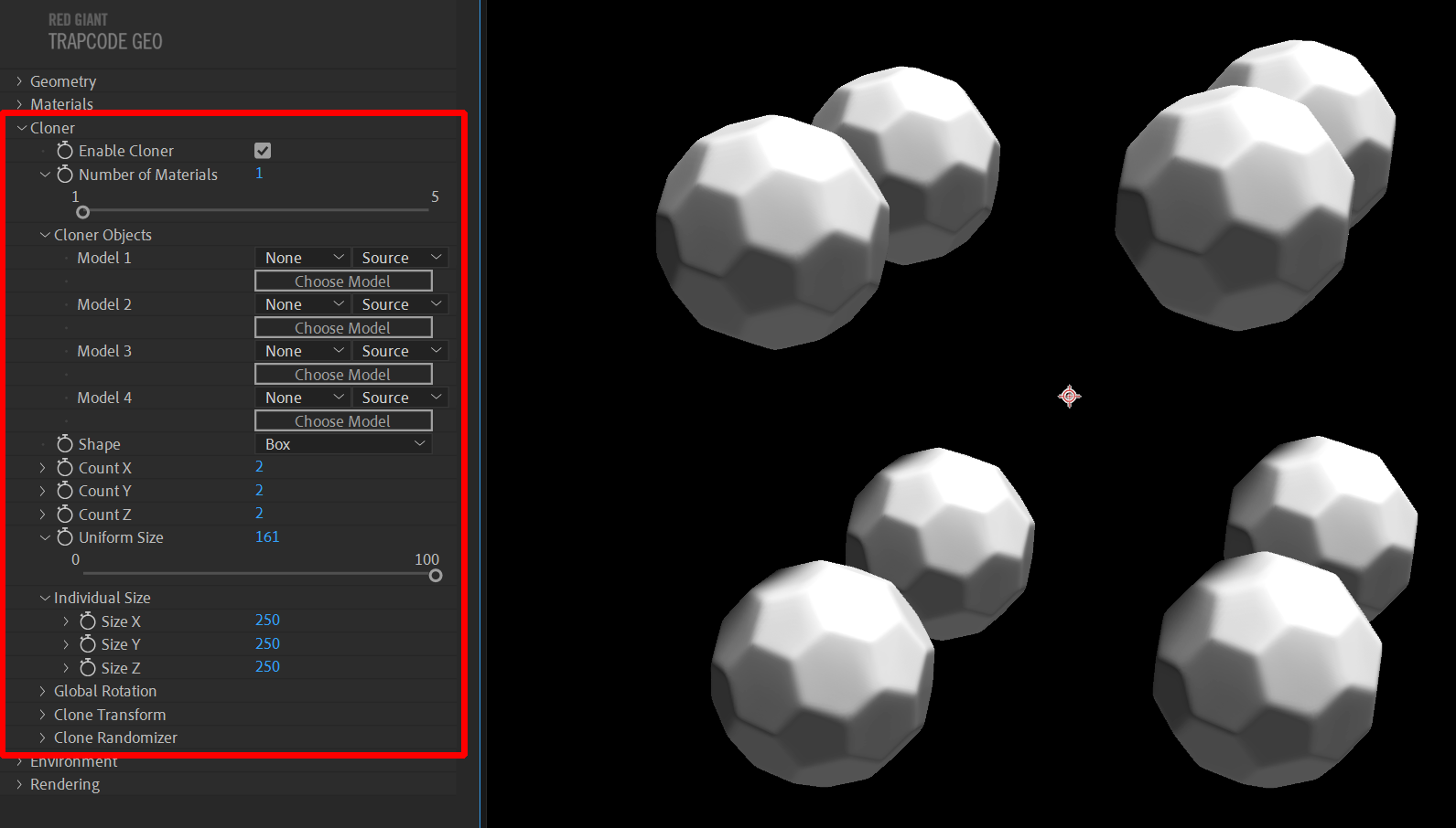
To activate the Cloner group’s features, begin by checking the Enable Cloner checkbox.
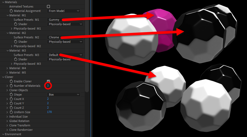
Number of Materials establishes how many of the five possible materials apply to your cloned objects. The image below shows this control in action with three materials selected. See the Materials Group page for more info on options here.
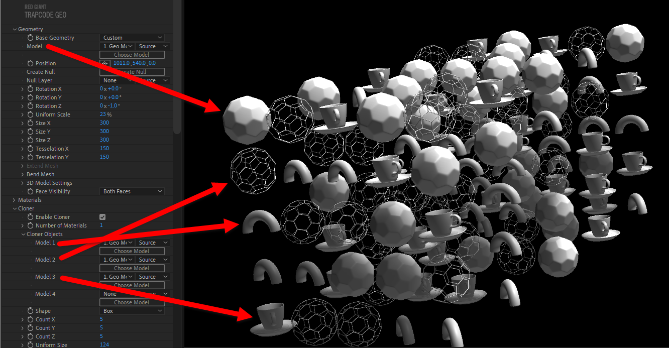
The Cloner Objects subgroup lets you select four models in addition to the Base Geometry model. In the following image, you see how we selected four models to populate our 5x5x5 Shape. Fun yet practical fact: We went through several iterations of this image with different Seed values before arriving at the version shown here, because we wanted each of the four models clearly visible in that first column.
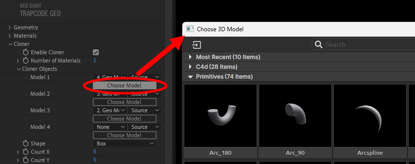
Within the Model 1/2/3/4 controls, use the Choose Model button to launch Geo's model browser, as shown below. Remember that you can use the square icon just above the words "Most Recent" to import external models into your Geo model collection. These appear in the Custom group at the bottom of the browser's contents.
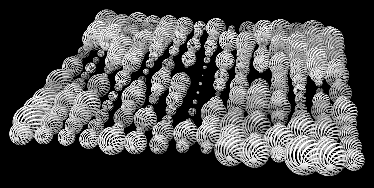
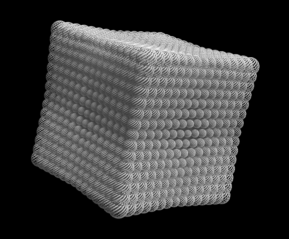
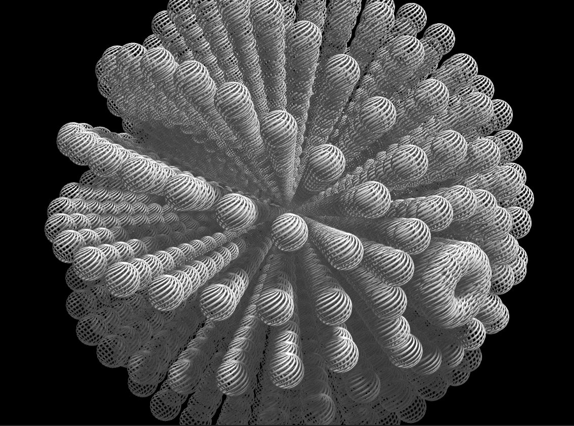
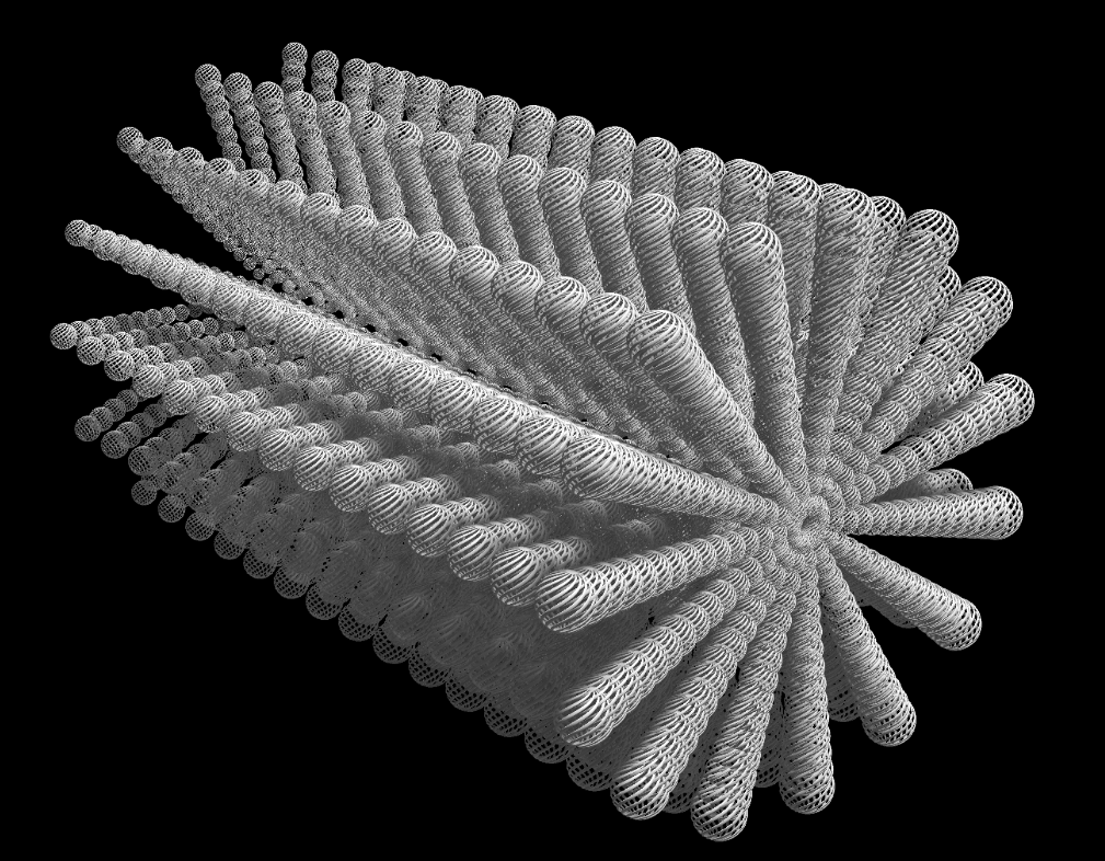
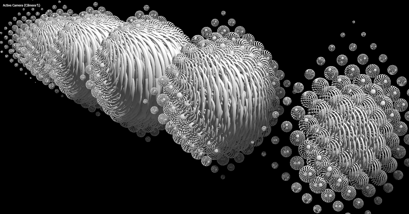
The Shape control essentially asks a question: You’re about to create copies of your original form, so how do you want those copies arranged? The following images show a 15x15x15 array of the Sphere_Strips_Twisted model organized according to this control’s three options — Box, Sphere, and Cylinder — shown below from top to bottom, respectively.
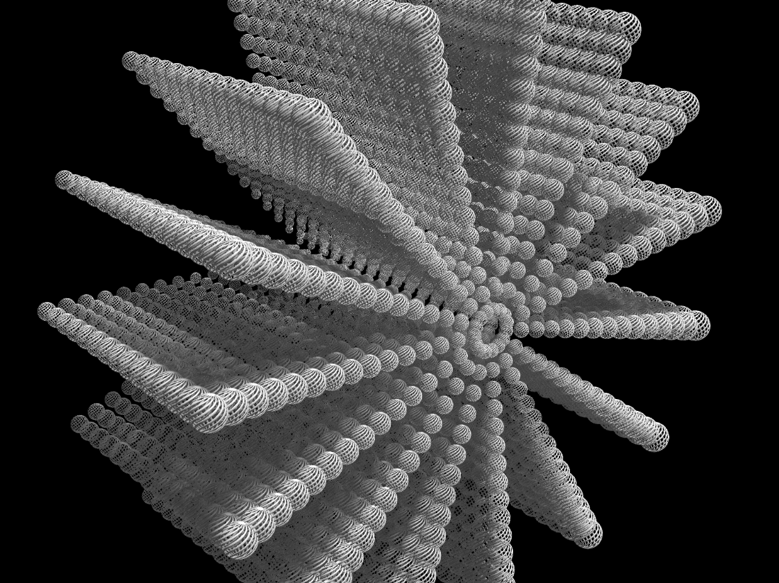
And if that last image doesn't say "cylinder" to you, here's the same configuration when we increase Individual Size > Size Z (see below) and lower Uniform Size.
But we're getting ahead of ourselves, so let’s unpack the above images a bit.
In all three shape cases above, we’ve used the Count X/Y/Z controls to create 15 models along each axis. Look closely at the above image and you'll see 15 ball shapes comprising each "spoke" radiating from the cylinder's center. You'll also count 15 of those spokes and a depth of 15 "wheels" in the cylinder shape.
Uniform Size controls the dimensions of the entire cloned shape, not the individual model elements within that shape. When you increase Uniform Size, all three dimensions of the shape increase in tandem to preserve the relative sizing of those dimensions. In contrast, Individual Size > Size X/Y/Z adjusts each shape dimension independently. Again, as noted with our cylinder above, our shape is longer than it is taller or wider because we increased the Size Z value.
We recommend setting Individual Size values first to get your shape how you want it, then using the Uniform Size control to change the whole form’s size without altering its relative dimensions.
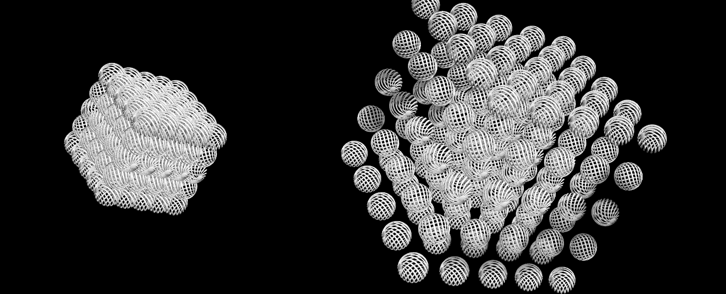
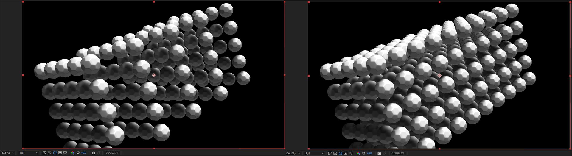
To drive these points home, below is a comparison of Uniform Size values at 50 (left) and 110 (right). Notice how the model size, angles, etc. remain consistent; only the distance between those models along all three axes changes.
And just to alleviate any potential confusion in terminology, the Geometry group's Uniform Scale and Size X/Y/Z (covered on the Geometry page) impact the individual model — each single swirly ball, given our example here — but the Cloner group's Uniform Size and Individual Size X/Y/Z impact the entire array/shape of cloned models.
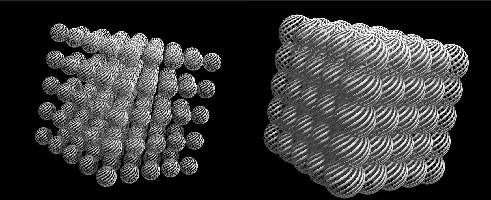
Let's see this distinction in action. Here's that same 5x5 box with (Geometry group's) Uniform Scale: 100 and Uniform Size: 200 (left), then we increase Uniform Scale to 200 (right). The individual models change, not the size of the box.
If you did want to change the box size in a non-uniform way, you could do it with (Cloner group's) Individual Size controls, which change the size of gap between models along a given axis. Again, note the 5x5 box above. Here's what happens when we increase Individual Size > Size X from 250 to 600:
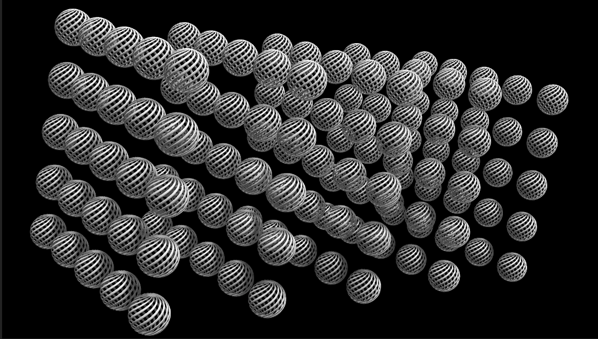
The square sheets, each comprised of a 5x5 model grid, remain unchanged, but the distance between those sheets has widened.
The following comparison shows how we increased the value of Individual Size > Size Z to extend the shape's depth. Increasing the Count Z from 5 to 10 doubles the number of square "sheets" but leaves the total box shape's dimensions unchanged.
Let's examine one more scenario. The image below shows a 2x2x2 formation of buckyballs in which (Geometry group's) Uniform Scale and (Cloner group's) Individual Sizeare both set to 100.
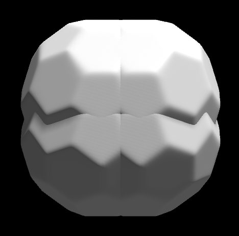
What if we want to separate our buckyballs? One approach could be to increase Cloner group's Uniform Size, perhaps to 500, like so:
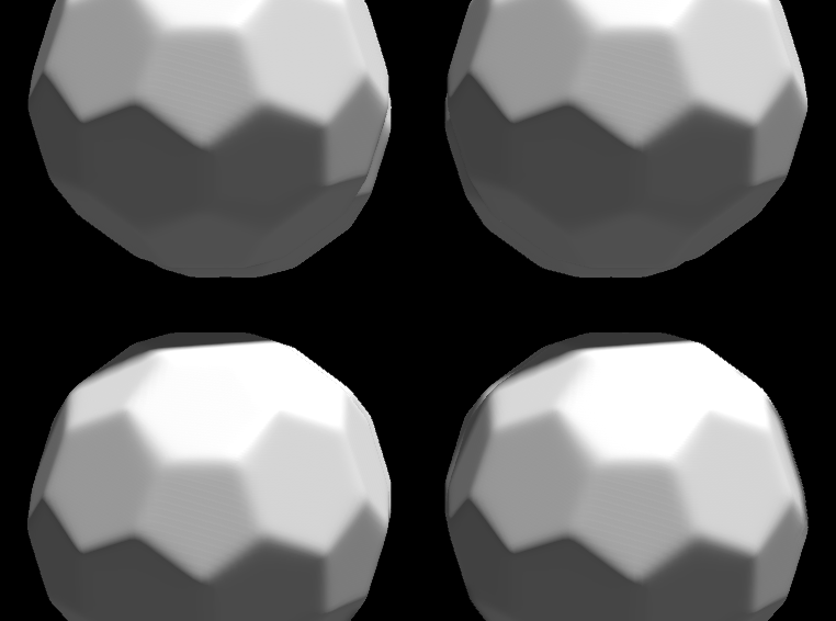
Model size remains unchanged while the gap between models increases. Alternatively, you could lower Geometry group's Uniform Scale to 20 percent:
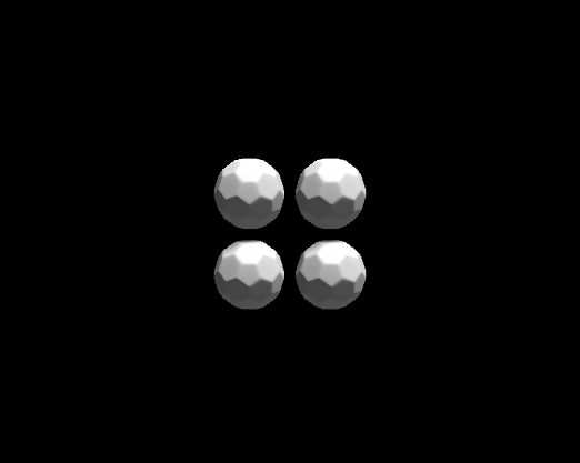
Lowering C Uniform Scale (in the Cloner > Clone Transform subgroup, see below) also shrinks the size of all models, but not by the same amount simultaneously. (We cover this in the next section with a larger, more illustrative array.) However, the center of each model remains fixed in 3D space, and this is one way to shrink models. You can see how the buckeyballs now appear small in our comp, which we could correct through repositioning the array, moving the camera, or other tactics.
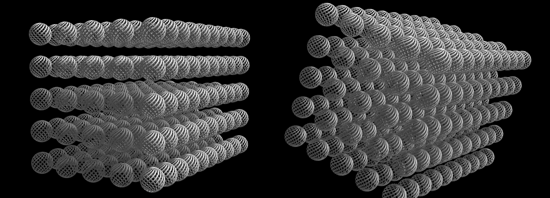
Global Rotation and its C Global Rotation X/Y/Z (Geo often abbreviates "Cloner" as "C") controls are fairly self-explanatory. You have three independent controls for rotating your entire cloned form along the x, y, or z axes. In the following example, we show a box form with 0 degrees of rotation on each axis (left), then we changed C Global Rotation X to 20 degrees (right).
Clone Transform
Unlike earlier Geometry and Cloner parameters, the Clone Transform subgroup controls how individual models behave within a cloned array. One way to say it is that you're introducing changes that propagate across the array.
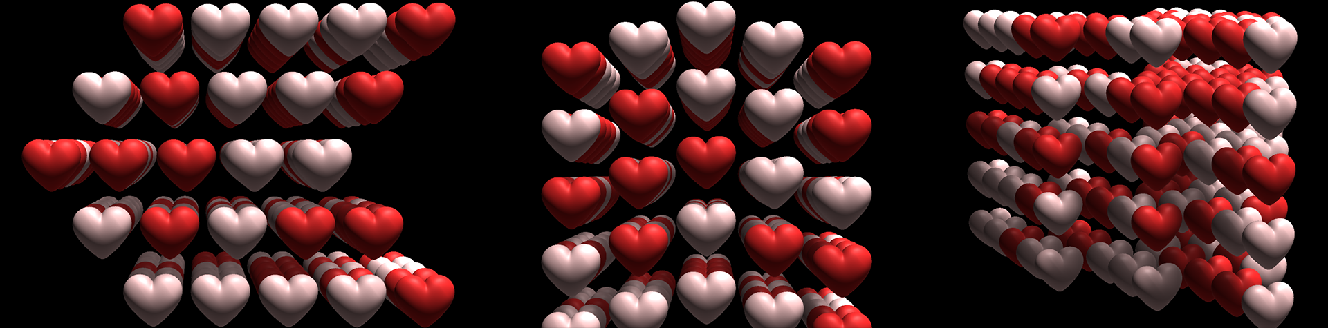
- C Position X/Y/Z shifts cloned models in incremental amounts along a given axis, up to the value you select for the outermost models. In the following triptych, we show C Position X: 30 (left), C Position Y: 12 (center), and C Position Z: 100 (right, with adjusted camera angle). In the C Position X example, for instance, the middle row reflects an unshifted value of 0. The rows on the top and bottom have values of 30. The second and fourth rows, reflecting the middle value between the two adjacent rows, has a value of 15, even though that's not stated anywhere.
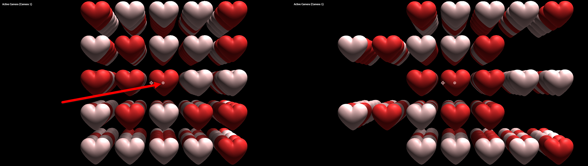
- C Position Offset X/Y/Z resembles C Position, but rather than building toward your given value from the center outward, this control implements the value and its negative in an alternating fashion across each row and column. This makes sense when you see it. Check out the image below, and keep your eye on the shape's center marker, which we've pointed out in the left image. In the right image, we set C Position Offset X to 20. Observe how the top row shifts to the right by 20, then the next row shifts left by 20 relative to the center, and so on.
- C Rotation X/Y/Z controls echo the same input methods as the Rotation controls in the Geometry group. However, whereas the Geometry controls rotate all models in unison, these C Rotation controls rotate the models along a given axis a certain amount across that axis. The amount of rotation depends on the order in which the clones were created, with the original mesh having no rotation while the “farthest” clones experience the most rotation. Once more, this is easier to grasp with an illustration.
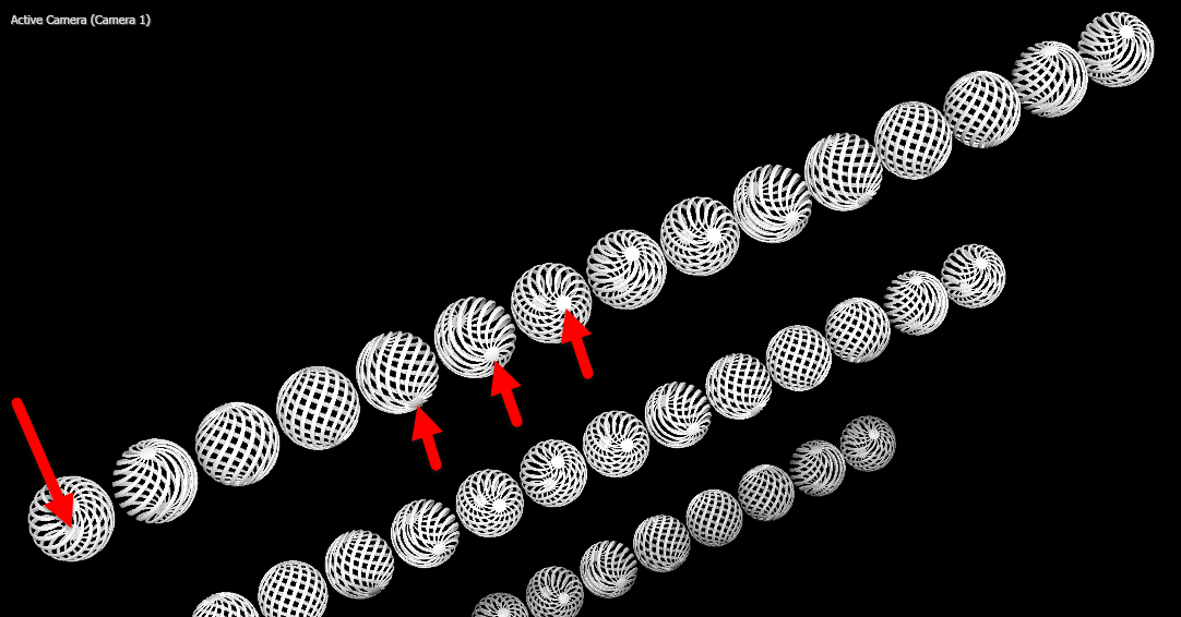
Our spiral ball model has a small, solid circle at its top and bottom. In the image above, we gave C Rotation X a value of 180 degrees. Thus, the white circle on the top of the ball at the center of our form ultimately "travels" all the way around to the bottom the ball at the edge, shown by the leftmost red arrow. - C Uniform Scale enlarges or shrinks all clone meshes across all three axes in coordination with Transform Ramp (see below). Like C Rotation X/Y/Z, C Uniform Scale varies the amount of scale applied to a clone with that clone’s “distance” from the original model.
In the next image, we compare the C Uniform Scale values of 35 (left) and 135 (right). At 100, every model in the array is the same size. They key point here is that values can be positive yet still yield diminishing sizes as models approach the shape's edge. In fact, we noticed with this box of hearts that the outermost models began to vanish around a value of 25.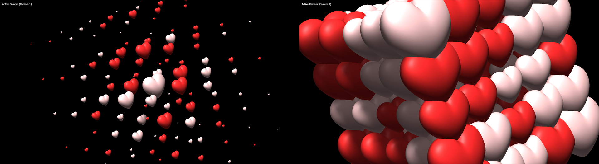
- C Scale X/Y/Z performs increasing or decreasing amounts of scaling to clones along a given axis.
- Transform Ramp. In all the above examples, we had Transform Ramp set at its default of 100. Thus, 100% of the ramping (or descaling, if you will) effect applied according to the C Uniform Scale parameter. We show this again in the left image below, with C Uniform Scale: 45 and Transform Ramp: 100. However, the right image shows what happens when we change Transform Ramp to only 50 percent. We're throttling back to only 50% of the total scaling specified by C Uniform Scale.
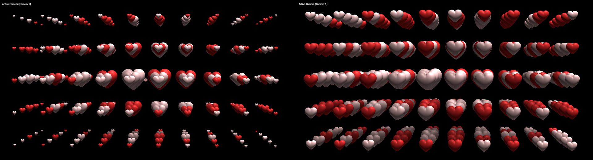
Negative values reverse this effect, as shown when we change Transform Ramp to -100 percent.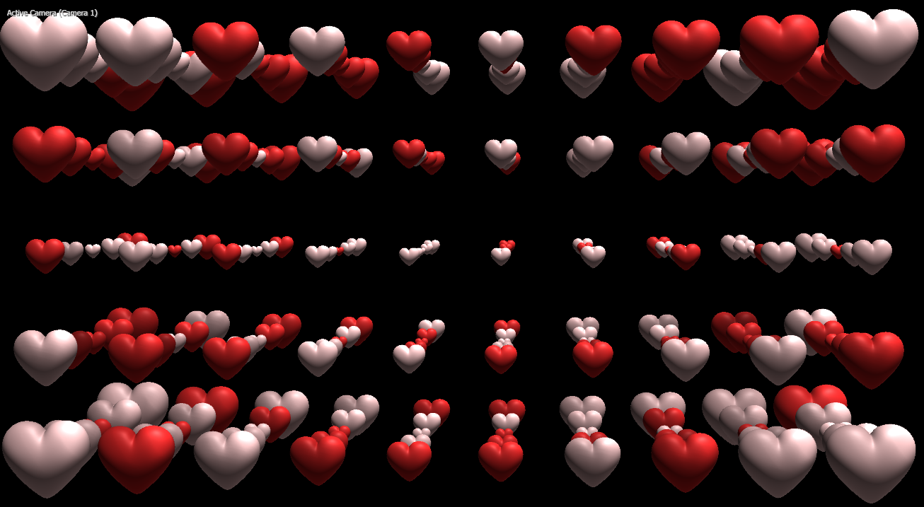
Note that Transform Ramp applies to all clone transform parameters — position, rotation, and scale. - Orient Inward/Outward governs how much clones face toward or away from the shape's center. Other rotation controls in the Geometry and Cloner groups can influence this orientation. The following animation, which cycles from 0 to -100 to 100 and back, demonstrates the behavior.
Clone Randomizer
Finally, the Cloner Randomizer subgroup makes changes to cloned meshes independently and randomly from one another.
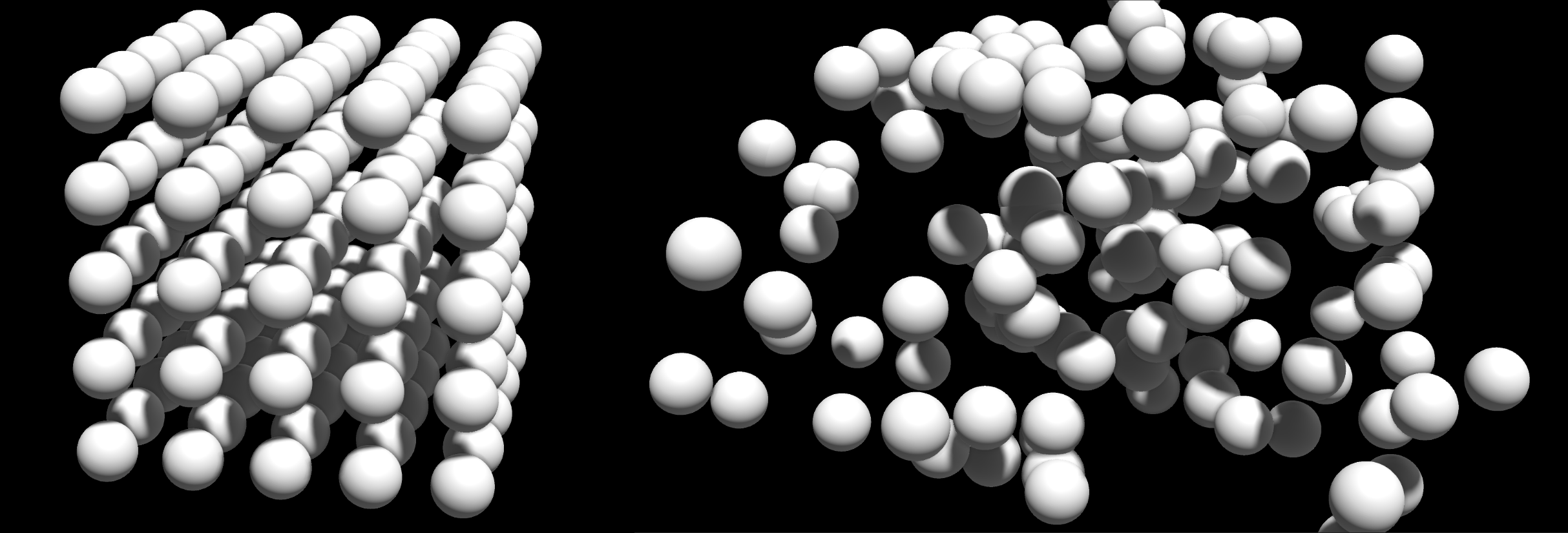
- C Randomize Position X/Y/Z moves clone positions along a given axis. The amount of randomization increases as values move away from 0. Control sliders span from 0 to 500, but you can manually enter or click-drag from -10000 to 10000. Below, you can observe the default setting of X: 0, Y:0, and Z: 0 (left) compared to values of X: 200, Y: -5, and Z: 200 (right).
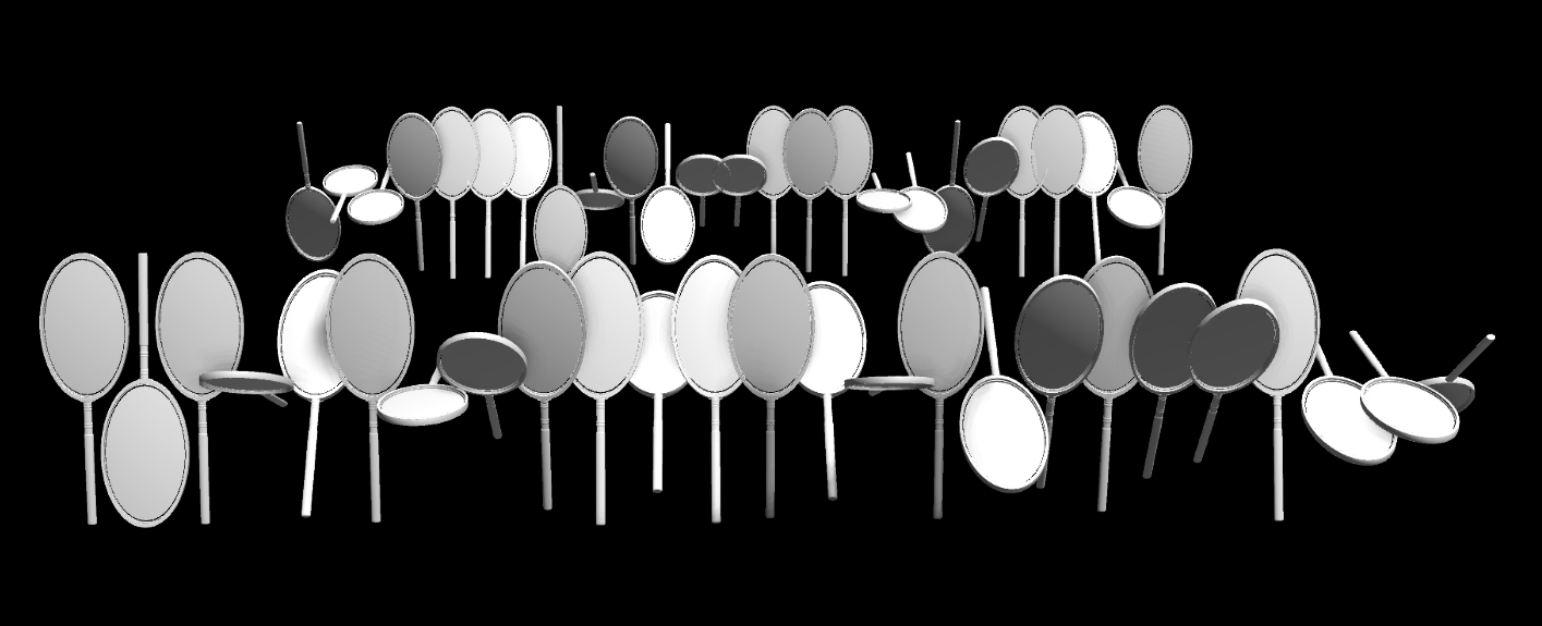
- C Randomize Rotation X/Y/Z lets you control the amount of randomized model rotation around a given axis. Note the ability to control rotation with both an angular dial control as well as manual and click-draggable fields. Here, you can see all values at default except for C Randomize Rotation X: 180.
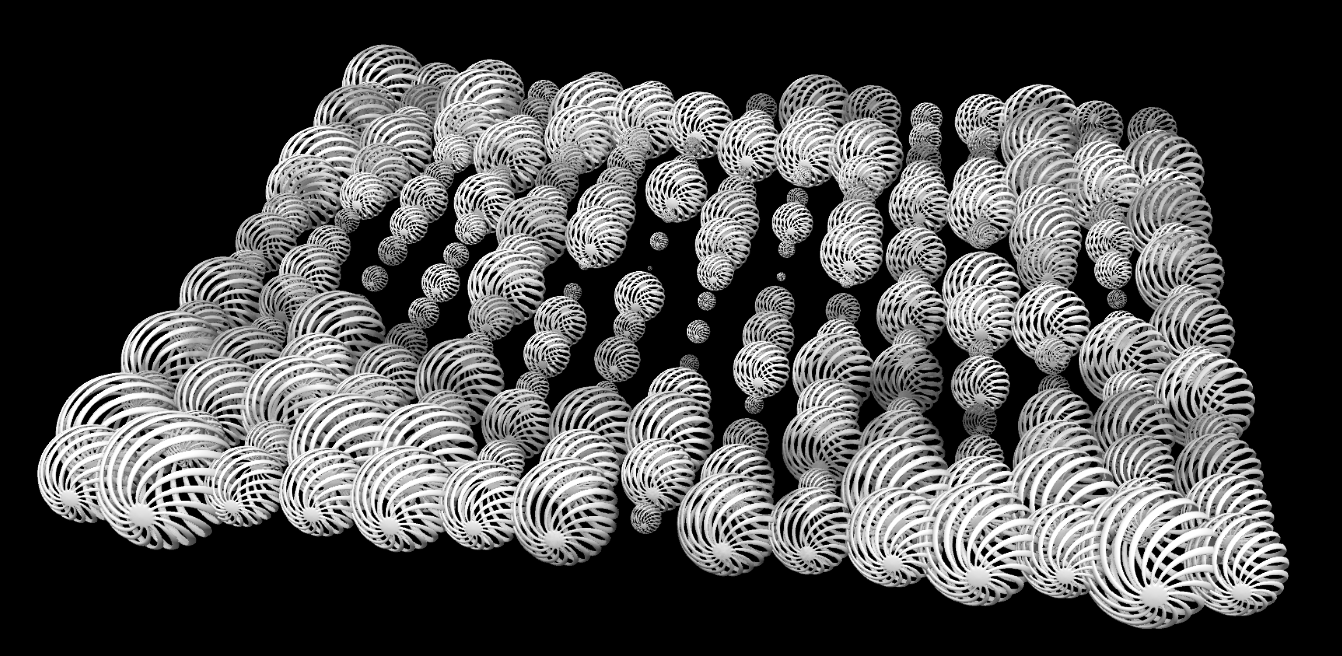
- C Randomize Uniform Scale changes (with percentage values from 0 to 2000) mesh size along all three scales uniformly. Your cubes will remain cubes, for example, but the amount of scaling for each cube will be randomized. Note that some meshes will get larger and others smaller. Higher values increase randomness. Here is the outcome on a 15x15 sheet of spiral spheres with the parameter set to 200 percent.
- C Randomize Scale X/Y/Z will apply randomized scaling across all clones, just like with C Randomize Uniform Scale, except only along the single axis selected.
- C Randomize Tone randomly applies grayscale values to all clones to provide some variation in their color values. The default 0% delivers no grayscale gradient. At 100%, the cloned shape is fully grayscale. Below, we show values of 0% (left), 50% (center), and 100% (right).

- Random Seed. If you’re not getting the random look you want from clones, try altering the Random Seed value. This changes the input value Geo uses to compute with its randomization algorithm. For example, compare the above image, which used a Random Seed of 2, with the following, which uses a Random Seed of 42000. The number doesn't really matter. The point is to generate a different set of computations for Geo's various random controls.