
Color
Here you select how color values are to be determined for the cloned objects. If you only want to assign a uniform material to the clones, for example, you can ignore these settings. In any case, the color values determined here can also be read out via a Color User Data node. Simply click on the Presets... button and select MoGraph > Color from the context menu or enter the abbreviation RSMGColor directly under Attribute name. The color values of the distribution can then also be evaluated for other properties of the material.
-
Constant: All object copies receive the identical color value, which you can freely define via Color.
-
Linear: A color gradient is provided that is used in full from left to right. You can then use the separate Direction setting to specify whether the gradient should be applied to the clones in a U- or V-direction.
-
Random: The colors of the color gradient are taken from a random position along the gradient for each object copy. These color values can be recalculated for each object copy by changing the Seed value.
-
Speed: In this mode, the clones' movement speeds are analyzed, and color values from the gradient are assigned accordingly. Slow or stationary clones are assigned the color from the left edge of the gradient, while fast clones are assigned the color from the right edge of the gradient. This mapping of speeds to the gradient can also be adjusted using the Range setting.
-
UV (Image): In this mode, you can link an image file or a video from which the colors will be extracted.
When using Sample Mode Constant, configure the desired color value for all clones here.
The Sample Modes for Linear, Random and Speed offer a color gradient, which is also available as a control element in many other areas of Cinema 4D.
 Click here to see a description of the standard color gradient.
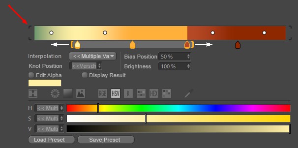
Gradients are used at many locations in Cinema 4D and make it possible to use color and alpha values to create linear gradients that run from left to right. Various types of interpolation are available, which can also be used to calculate automatic transitions between the colors and alpha values you have placed. Note that you can access further parameters (described below) by clicking on the small arrow to the right of the color gradient.
The small, square color fields directly below the gradient (called Knots) determine the colors and their positions in the gradient. To add a new Knot, simply place your mouse pointer just below the gradient. A semi-transparent color tab appears, which can be moved sideways together with the mouse pointer. A click then creates a new color tab. To remove excess color tabs from the gradient, simply drag them up or down out of the gradient with the mouse.
To change the color of a color tab, select it by simply clicking on it. Below the gradient, settings for the exact position of this color on the gradient, the interpolation used on this tab to the neighboring color on the left and, of course, the standard color sliders for adjusting the color are displayed. Some interpolation types also offer additional Knots on the gradient, which are visible as small circles between the color tabs. This can be used to change the mixing point at the color transition between the colors. These Bias Handles can also be moved directly with the mouse or placed with numerical precision by simply clicking on a numerical value for the bias position.
If you also hold the Shift key when moving color, alpha or Bias Handles, the movement will be performed in 5% increments.
Several Knots can also be selected at the same time. To do this, you can select the Knots one after the other using Shift + click (or remove them from the selection again using Ctrl-click) or hold down the left mouse button directly in the color gradient and drag a selection frame over the desired Knots from there. Orange brackets appear around the selected Knots below the gradient. All Knots contained in such a bracket can be moved together along the course if you place the mouse pointer between the brackets and then drag them with the left mouse button held down. Pulling on the Knots will scale the distances between the Knots within the brackets. The colors cannot be placed outside the boundaries of the gradient. If you move a group of color tabs too far to the left or right, the outer color tabs will automatically stop at the edges of the gradient and their distance to the subsequent colors may be reduced as a result.
Similarly, the bias Knots can be selected in groups and then moved together. However, no separate Knot symbols will be displayed. Selected Bias Handles can be recognized by the black coloring, whereas unselected Knots use a white circle as a symbol.
A double-click in the color gradient selected all Knots, a single click deselects everything. Double-click on a Knot to display all settings in a separate window. If there are several Knots on top of each other, they can be right-clicked to select one of them from a list that appears (selected Knots are enclosed in square brackets).
The gradient can be moved or scaled horizontally (see below). In the latter case, brackets appear around the color gradient (red marking at the top of the image). Clicking on these brackets scales the color gradient back to 100%.
Selected Knots can also be moved using the cursor keys (left, right). Shift also quantizes in 5% steps here. The cursor up and down keys adjust the Knot brightness (old color gradient only).
The following buttons apply for navigation within the color gradient - similar to the Timeline:
- 1, Middle mouse button: Move (only possible with enlarged color gradient)
- 2, Mouse wheel, Alt + right mouse button: zoom in and out
- S: Show selected
- H: Show all or scale to 100%.
Right-click on the color gradient to open a context menu with the following commands:
Invert Gradient
This reverses the color gradient and thus the order of the colors.
Double Knots
This defines the current color gradient to its own end, doubling the Knots and the color gradient.
Distribute Knots
This sets the Knot distances to identical values.
Bias Handle
If Bias Handles (the small circles in the color gradient) are to be displayed, this option must be activated.
Interpolation of all Knots
This lets you set the interpolation of ALL Knots - regardless of the selection - at the same time.
Size
This can be used to define the vertical size of the color gradient in 3 stages. This setting is also available as a program default setting (Units tab).
Interpolation
Several interpolation methods are available to control the behavior of the color values between the Knots. Each Knot can have its own interpolation!
Soft/Cubic/Cubic Bias/Linear/Step/Blend
The color transition from one selected Knot to the next takes place as indicated by the small curve symbols in front of each option. Most interpolation types also use the Bias Handles to place the color transition between the adjacent colors as desired. Only with Step interpolation will there be no Bias Handles, as the color change will always take place abruptly when the next color Knot to the right is reached.
Step
There is no interpolation at all. The color changes abruptly without transition at the position of the next touch.
Knot position
The position of selected Knots can be defined numerically here. 0% = left edge, 100% = right edge.
Bias position
This parameter defines the position of selected Bias Handles between the adjacent colors. 0% = left color or alpha Knot, 100% = right color or alpha Knot.
Brightness
Brightness can also be used to control the brightness of selected Knots above 100%. They generate overbright colors (HDR) that the color selector cannot provide on its own.
Edit Alpha
Activate this option to work on the alpha values associated with the color gradient. The creation, placement and setting are carried out in the same way as already described for the color Knots. The only difference is that only percentage values and therefore no colors can be assigned for the alpha Knots via a Brightness value. The curve interprets 0% as black and 100% as white. Values between 0% and 100% are often used here by default, but brightness values above 100% can also be assigned.
The alpha Knots can be placed completely independently of the colors. Therefore, all color Knots and their gradients are also hidden by default in this mode.
Display Result
This option displays the color gradient taking the alpha channel into account. This means you can practically display the opacity of the alpha Knots overlaid with the colors while you work on the placement and values of the alpha Knots.
Load Preset
Save Preset
Color gradients can be saved and reloaded at any time using these two commands.
When the Save Preset command is executed, a small dialog window will open where the preset name and other information can be entered.
Click on Load Preset to open a small selection window where you can load the corresponding preset with a single click. There you will already find a selection of common color gradients, even if you have not yet saved your own.
General details regarding the Preset System in Cinema 4D can be found there.
This setting is available only in Linear Sample Mode and determines whether the color gradient should be applied across the clones in the U or V direction.
This setting is available only for Sample Mode Speed and offers the following options:
-
Automatic: The available range of speeds is automatically calculated and applied to the color gradient. As a result, all colors in the gradient are always visible in the distribution, unless the clones are static.
-
Manual: The separate Min Speed and Max Speed values allow you to specify a range of speeds that is compared to the actual speed of the clones. Clones that are slower than Min Speed are assigned the color from the left edge of the gradient, and clones that are faster than Max Speed are assigned the color from the right edge of the gradient. Speeds in between are assigned the corresponding color values from the gradient.
With Range Manual, you can manually specify a speed range to which the entire color gradient should be mapped. Unlike Range Automatic, this manual setting also allows you to assign colors from the inner gradient to only a portion of the speeds. All clones whose speeds are less than the Min Speed or greater than the Max Speed will consistently be assigned the corresponding color from the left or right edge of the gradient.
This setting is available for Sample Mode UV (Image) and offers the following options:
-
Origin: The UV coordinates determined in the original, undistorted, and unscaled grid are used to read the color pixels from the loaded image or video.
-
Current: In this mode, the actual positions of the clones are used, and their actual UV coordinates are evaluated to read color values from the loaded image (see Path specification).
This setting applies when a video file is specified in the “Path” field. In that case, you can use these options to choose how the file should be read.
-
Frame: In this mode, you can use a specific Frame from the video file for color output by specifying the frame number.
-
Live: With this method, the next frame from the loaded video file is automatically loaded and processed with each successive frame of the animation. You can use the Offset value to manually advance this processing frame by frame.
Here, you can click the small folder icon next to the path field to open a file dialog and upload an image or video. Alternatively, you can click the Library icon to select a file from the Asset Browser.
For Animate Live, you can set an additional frame offset here to be used when reading colors from a video.
For Animate Frame, you can specify here the frame number you want to use from a loaded video.