

Layer Controls
This setting defines how the values of the particles will be transferred to the points or the 3D space. You will also find examples of the different modes in the following illustrations:
- Nearest: Each spatial area and each point covered by the Particle Field will be assigned the value of the particle that is closest to it. There is no spatial limitation of the transmission, unless you combine this field with other, spatially limited fields, for example. This is often a better setting for the transfer of vectors to a Field Force object.
- Index: This mode is very special because the particle values will not be transferred depending on the proximity to points, but sequentially to the corresponding point indices. If, for example, there are more points on an object to which the particle properties should be transferred as a Vertex Map than there are particles, a corresponding number of points will remain on the object without a vertex map weighting (see also the example in the following figure). Also note the Unique ID mapping option in this mode.
- Average: Only the areas within the Radius distance around the particles are assigned values. If the areas of influence of several particles overlap, average values are determined in the overlapping areas.
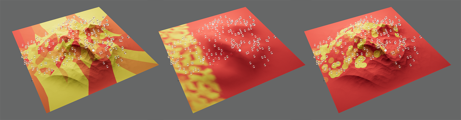 On the left is the Nearest mode, in the middle Index and on the right Average. The different radii of the particles were evaluated and interpreted as the weighting of a vertex map.
The environment of the particles is also evaluated via the Radius setting in the two remaining modes:
- Min.: If the areas of influence defined by the Radius of several particles overlap, only the smallest value will be used within this overlap. Particles with smaller values will mask the effect of particles with larger values.
- Max.: If the areas of influence defined by the Radius of several particles overlap, only the largest value is used within this overlap. Particles with higher values will mask the influence of particles with lower values.
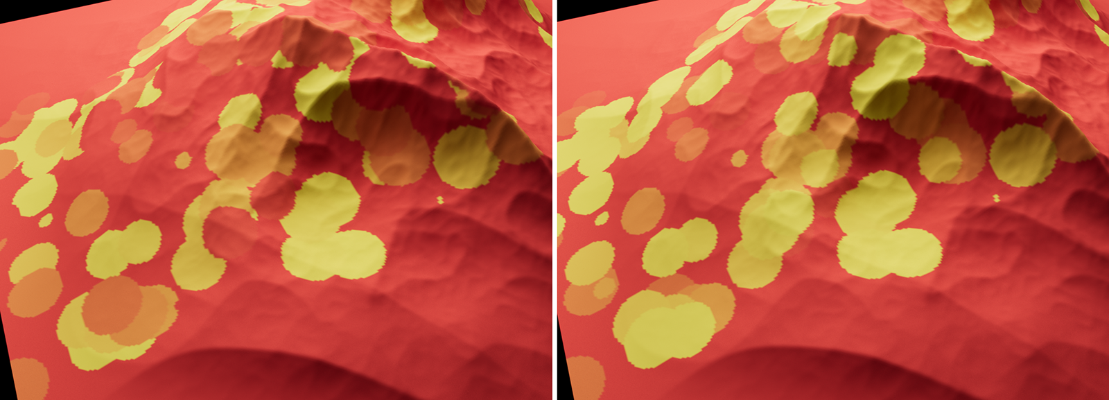 On the left is the Min. mode, in which the particle with the smaller value will always be displayed in the case of overlapping particles. For comparison, the Max. mode is shown on the right-hand side. There, the maximum values will always conceal lower values. In this example, the different radii of the particles were evaluated.
This setting is only available when Index mode is selected and defines how the particle IDs should be transferred to the point IDs:
- Option off: The point IDs will simply be linked to the number of currently visible particles. If a particle is destroyed and a new particle is created at the same time, the total number of particles will remain the same and therefore the same number of points (always starting with the point with the index number 0) will be assigned values. This case can be seen on the left half of the following video.
- Option on: The individual particle ID is linked to the same point ID. If a particle is deleted, the nearest newly-created particle will be assigned the nearest free ID that is greater than the particle IDs already assigned. Accordingly, each time a particle is removed, the point ID for the value assignment of the nearest, newly-created particle will increase, as shown in the right half of the following video.
If you want to use the radius defined by the particle system (each particle can have its own radius), activate this option. Otherwise, a constant Radius can be defined with the following parameter Radius.
For the Average, Max. and Min. Enter the distance from each particle at which it transmits its values. Areas that lie outside this spherical area around the position of the particles will not be taken into account. Use the Clip to Shape option to define which values should be assigned to these external areas.
Value Source[-2147483648..2147483647]
If you use the Particle Field to transfer colors or weightings to Vertex Map or Vertex Color Tags, for example, you can use this menu to select which property of the particle should be used for this. Please note that it may be necessary to adjust the order of magnitude depending on the selected property. Think, for example, of the Velocity, the Distance traveled or the Lifetime of a particle, which must then be converted to the typical value range of a vertex map between 0 and 1.
To do this, use the Remapping area of the Particle Field or - for the conversion of very large property values - the Range Map Modifier Layer in the filter list (see example below).
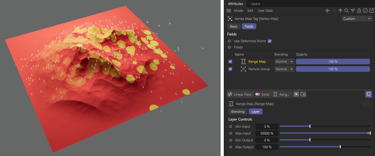 Here, the Distance values of the particles will be transferred to a vertex map. A Range Converter Modifier is used here to adjust the value range of the distances (see right-hand side of the figure).
For the transfer of vectors (see Direction Source setting), you can instead use the Direction Source on the Particle Field to adjust the order of magnitude of the particle property values for the transfer.
In general, the Value Source is only used in the immediate vicinity of the particle, defined by the Radius value. Exceptions to this are the Nearest and Index modes, where the value transfer does not necessarily take place at the position of the particle. In addition, the Value Source can also be used as a multiplier, e.g., for normalized velocity vectors, when transferring vectors.
- Curve: The maximum value will be output at the position of the particle, which then decreases until the outer Radius distance is reached. This decrease and value distribution within the radius can be configured via the Remapping settings of the Field Layer.
- Speed: The velocity amount of the particle is output.
- Age: The age of the particles measured in images is output.
- Lifetime: The maximum lifetime of the particles is queried.
- Radius: The Radius property of the particle is queried. Note that this has nothing to do with the Radius that you can set on the Particle Field.
- Distance: The distance traveled by the particles.
- Angular Velocity (Magnitude): This is the amount of velocity of the particle rotation.
- User def. Property: The simulation settings for particles can also be used to bind your own variables to the particles. Find out more here. These variables can be read out via some particle modifiers and also filled with values. By selecting this value source, you also have access to this data within the particle field level. To do this, enter the name of the corresponding user property in the text field directly below or select the corresponding data record directly via the small drop-down menu to the right of the text field.
Color Source[-2147483648..2147483647]
This setting enables the transfer of color values, e.g., to transfer particle colors to vertex colors. These options are available:
- Color: The current color of the particles is read out and transferred to the field.
- User def. Property: The simulation settings for particles can also be used to bind your own variables to the particles. Find out more here. These variables can be read out via some particle modifiers and also filled with values. By selecting this color source, you also have access to this data within the particle field level. To do this, enter the name of the corresponding user property in the text field directly below or select the corresponding data record directly via the small drop-down menu to the right of the text field.
Below you will find an example where the colors of newly emitted particles (shown on the left) are first transferred to a Vertex Color tag that lies on a highly subdivided layer. This layer is used as a Pyro emitter, using the vertex color tag to color the density emission. The Pyro simulation can be influenced by the particle movement by simultaneously transferring the flight speed and flight direction of the particles (see value source and direction source) via Force Field object (see right half of the following video).
Wherever direction vectors can also be transmitted through a field, the flight directions or the current rotation axes of the particles, for example, can also be output. This is possible via a Field Force object, for example.
These particle properties can be output for this purpose:
- Velocity: The current velocity vector of the particles can be output here. This is therefore the normalized flight direction multiplied by the flight velocity. With the additional options of being able to link this vector to other particle properties via the Direction settings, this is probably the mode you will use most often for evaluating vector properties.
- To Particles: The direction vector between a position source in the Fields list and each particle is calculated here.
- Angular Velocity: Here you get the individual direction of all particle rotation axes.
- User def. Property: The simulation settings for particles can also be used to bind your own variables to the particles. Find out more here. These variables can be read out via some particle modifiers and also filled with values. By selecting this direction source, you also have access to this data within the particle field level. To do this, enter the name of the corresponding user property in the text field directly below or select the corresponding data record directly via the small drop-down menu to the right of the text field.
In the following video you can see an example where the flight movements (Direction Source Speed) of the blue particles are transferred to the red particles via a Field Force object in this way. The magnitude of the Direction Source output can be individually adjusted via the settings in the Direction tab on the Particle Field Layer.
In this context, please also note that the strength of a newly called up Field Force object is preset to 5. This will give you vectors that are already five times longer and you should then reduce this strength to 1 if necessary.
This function is often required for spaces that have an inside and an outside. This is entirely logical for the shape Fields (e.g., Spherical Field) but less obvious for particle, spline and volume objects, etc. Volume objects often have settings such as radius, with which a space can also be placed around a point or they define the space themselves. There is always an inside and an outside. This function defines how the inside should be treated. If nothing should happen (option enabled) or should null values, for example, be applied (option disabled), which will hide Fields below it if Blending Mode is set to Normal.
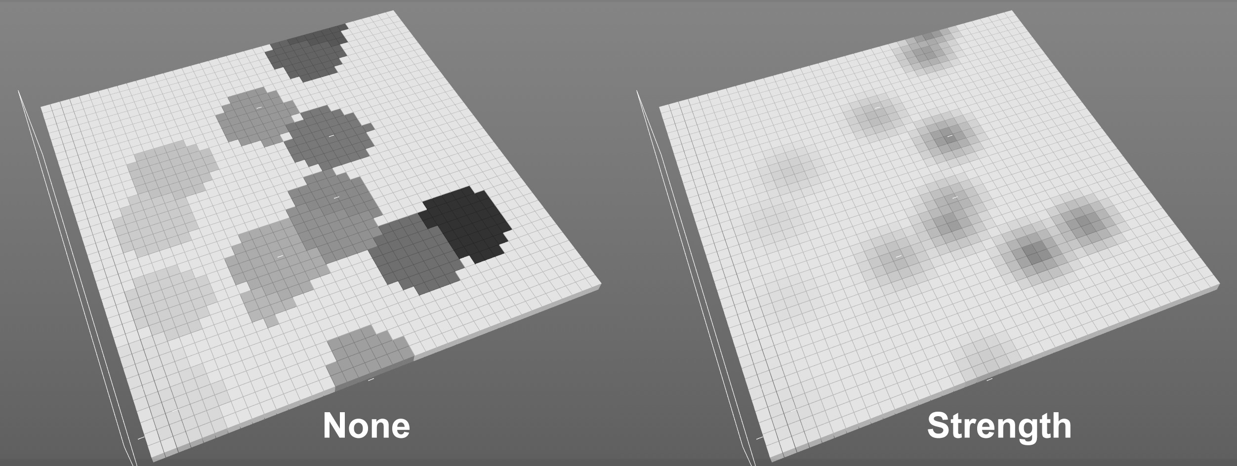 The two color alpha modes.
Please note that these color settings only have an effect if Remapping is deactivated in the Color Remapping tab.
They will then provide an alpha for the color channel that changes with the particle lifetime.
You have the following two options:
- None: The Value field channel is ignored and no alpha decrease from particle position to radius is generated.
- Strength: The Value field channel is included in the calculation (but without taking the settings of the Remapping tab into account).