
Inputs
Here you can route the geometry to the Node that you want to duplicate symmetrically. The Node also offers editing functions. It is therefore not necessary to use the entire geometry.
This is used to define the position and rotation of the axis system on which the mirroring should take place. If, for example, a head should be modeled by mirroring half a face, the axis system would have to lie on the plane between the halves of the face and be aligned accordingly with one of its pairs of axes. The following image shows a simple example.
The image on the left shows an example of Planar symmetry, in which one or more axes can be mirrored. The image on the right shows a possible result when using Radial symmetry, in which one of the symmetry axes is mirrored in a circle. In both examples, a simple plane was mirrored, which is highlighted in color in the image. The small axis system in the illustration only serves to clarify where the symmetry axis system has been positioned with the position and rotation values.
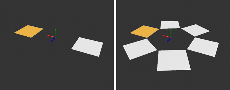 Planar symmetry on the left, Radial symmetry on the right. Both results depend on the position and direction of the symmetry system, which is placed by position and rotation.
As already demonstrated in the image above, two modes are available:
-
Planar: The geometry will be mirrored axially symmetrically along the directions defined by X, Y and Z. The starting point for this is the position of the symmetry system, whose axes are also used for the X, Y and Z descriptions.
-
Radial: This multiplies the geometry radially around the origin of the symmetry object like a gondola on a chain carousel. The setting for Axis defines the axis of rotation.
Planar settings
For the Planar Type setting, you will find the individual settings described below.
X, Y, Z can be used to define the axis directions along which mirroring is to take place. The axes refer to the symmetry axis system defined via Position and Rotation.
- Off: There will be no reflection along this axis.
- + to -: The geometry parts on the positive axis will be mirrored on the negative axis side.
- - to +: The geometry parts on the negative axis will be mirrored to the positive axis side.
This means that up to three mirroring directions corresponding to the three dimensions can be defined simultaneously, although one direction is often sufficient, e.g., to complete a face or a car body by mirroring one half.
Radial settings
With the Radial Type setting, you will find the individual radially symmetrical settings described below.
Select the axis direction around which the geometry should be rotated and duplicated. The selected axis is based on the axis system, which you can Position and Rotation freely in the room.
This can be used to rotate the radially symmetrical mirroring planes around the selected mirroring axis.
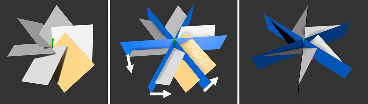 The initial state with a rotated polygon (marked yellow) is shown on the left. The position of the rotation segments is marked in blue. If the Cut Along Plane and Remove Outside options are active, only part of the polygon will remain visible here. By rotating the sectors (indicated by the arrows in the middle image), the position of the cuts along the geometry and thus also the final shape can be additionally affected.
Enter here the number of pie slices within which radially symmetric multiplication should be performed. In the example in the image above, there are six segments.
If this option is activated, an additional mirror plane will be assumed in the center of each pie slice, which reflects planar symmetrically per pie slice. The following image shows an example of this.
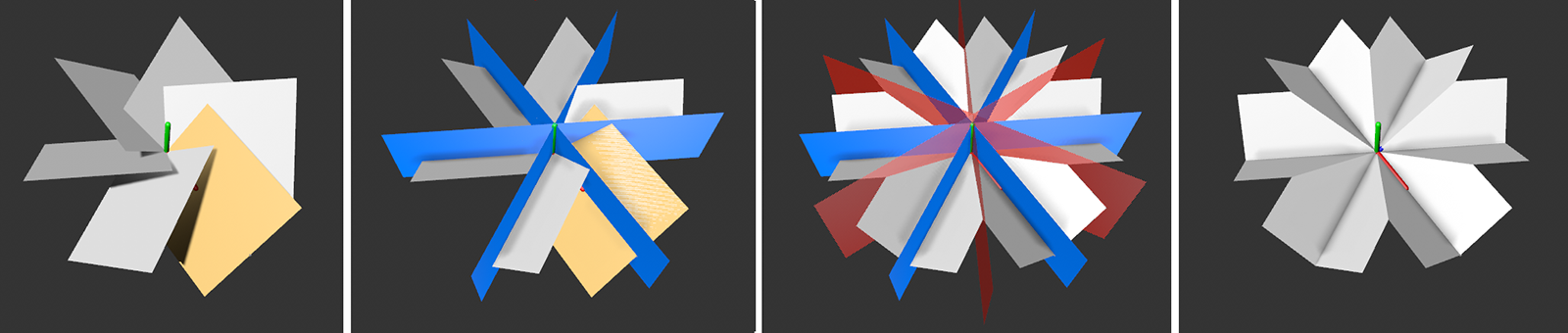
The image above shows a simple plane on the left (marked yellow), which is duplicated six times with Radial symmetry. By activating the Cut Along Plane and Remove Outside options, only the components of this planes that lie within the sector defined under Source Slice will be processed (second display from the left). By activating Mirror, a separation will be made internally in the middle of each sector (see red markings in the image). The geometry is also cut and mirrored at this center plane. A possible result can be seen on the far right of the image.
Source Slice[-2147483648..2147483647]
This setting is particularly important if the Remove Outside option is activated. You can then use this numerical value to define the number of the pie slice whose contents should be duplicated radially symmetrically. This is particularly relevant if your initial geometry is located in several rotation sectors at the same time. The following image makes this clearer.
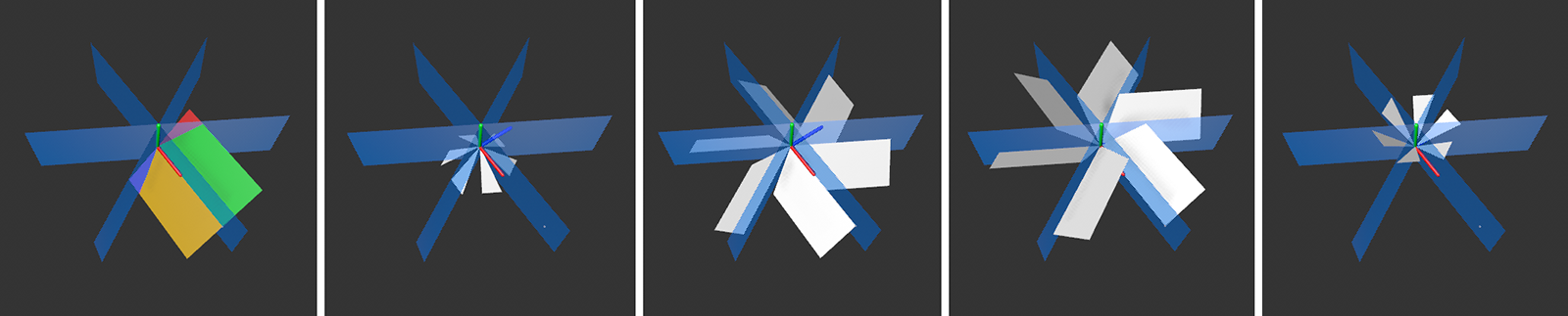 A simple polygon is used as the geometry here. The blue elements represent the limits of the six rotation sectors at the symmetry (number = 6). The polygon lies in four of these sectors. The corresponding sections of the geometry are marked in red, green, yellow and purple. The desired part of the geometry can be selected via Source Slice . The results vary accordingly, as the four images on the right show.
If a cut should be made along the symmetry planes, activate this option, then the Remove Outside option can also be used to cut away superfluous elements. Please note that a geometry that projects into several rotation sectors can also result in several cuts (see also the following image).
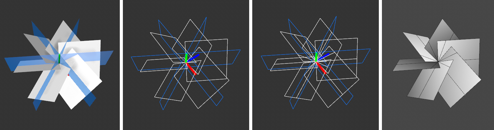 On the left, a rotated polygon was used, which was duplicated rotationally symmetrically. The boundaries of the rotation sectors are indicated by blue planes. If the option for Cut Along Plane is deactivated, the geometry will remain unchanged (see wireframe in the second overlay). Only by Cut Along Plane will subdivisions be added to the polygons when each sector boundary is penetrated (as shown in the two insets on the right).
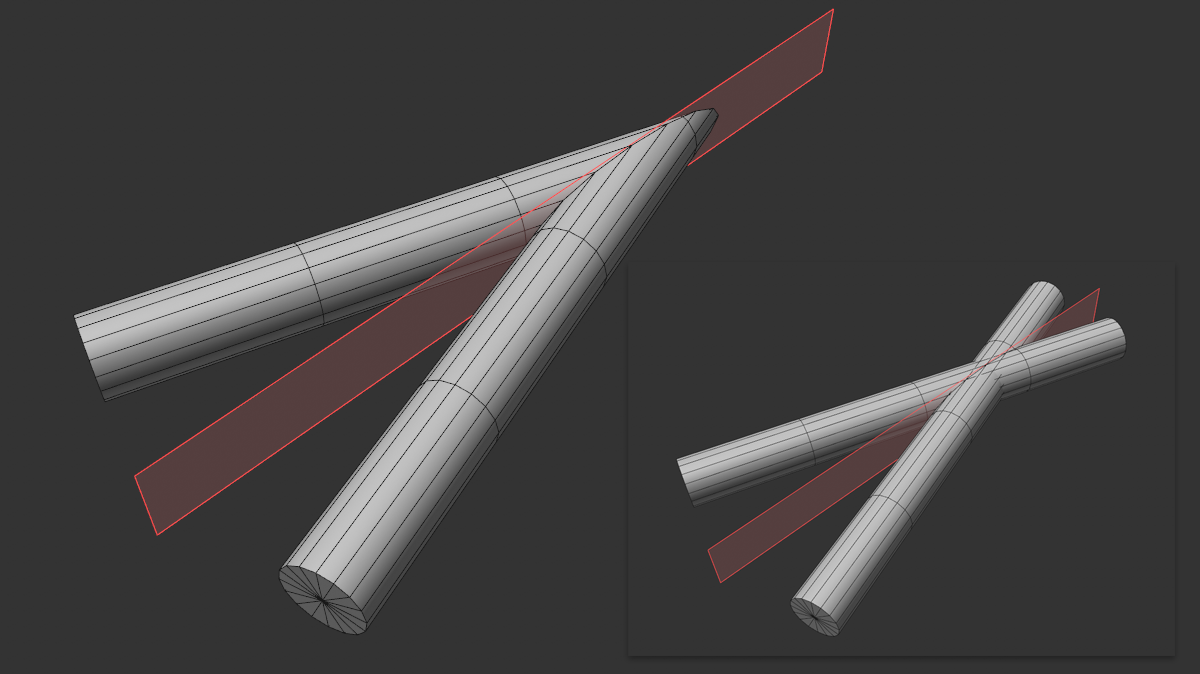
The example above shows the use of a Planar symmetry with a rotated cylinder. Use this option to define whether object components beyond the symmetry plane should be cut off (left option activated) or retained (right option deactivated) when using Cut Along Plane at the same time. This can even be practical if you already have a symmetrical object, such as a head, and want to edit it symmetrically without having to delete one half of the head first.
The following image shows another example, this time using the radially symmetrical function of the Node. Here too, Cut Along Plane must also be activated so that new points and edges can be created along the sector boundaries. In the case of radially symmetrical symmetry, the desired section can also be selected using the Source Slice for cross-sector geometry.
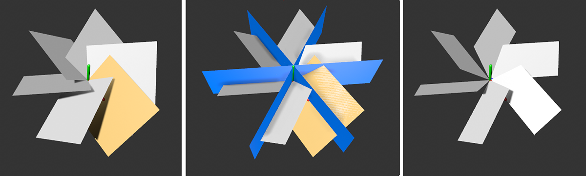
The image on the left shows the initial situation. A slightly rotated polygon (marked yellow) is multiplied radially symmetrically. By activating Cut Along Plane and Remove Outside, the boundaries of the rotation sectors (marked in blue) separate the polygons. Only the relevant sections will then be retained.
These settings belong together and can be used to combine points that lie on or in close proximity to the symmetry planes or boundaries of the rotation sectors. The following image shows two examples. The left-hand column shows an example without activated Weld Seam. For clarity, the points near symmetry planes have been marked in red.
As can be seen at the top left, the points in the center, between the radial sector boundaries, are also included when using the Mirror option. By activating Weld Seam, these points lying directly on the symmetry planes and mirroring planes will be first to be combined into one position. If Dissolve is active at the same time, the points lying on the mirror or symmetry planes will also be deleted. The surrounding polygons adjust automatically (see result in the top right of the following image).
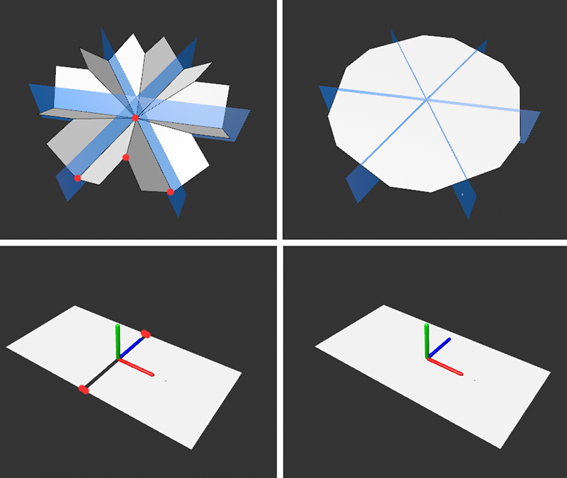
As can be seen in the image above left, the points in the center, between the radial sector boundaries, are also included when using the Mirror option. By activating Weld Seams, these points lying directly on the symmetry planes and mirroring planes are first combined into one position. If Dissolve is active at the same time, these points lying on the mirror or symmetry planes are also deleted. The surrounding polygons will be adjusted automatically (see result in the right-hand column of the image above).
As can be seen in the example with the Planar symmetry in the bottom line, it is even possible to combine points that are further away from the symmetry axes. Simply adjust the Tolerance radius accordingly. The larger this value is, the further away the points will be grouped. However, these points cannot be additionally removed by dissolving.