

Options
Here you can define the degree to which an edge selection should follow the surface curvature created by neighboring edges/edge loops. This value can be adjusted interactively by clicking and dragging in the Viewport.
This setting should be used only if surface curvatures behave strangely. Play around with the values if you get unexpected results.
The following example shows how the value works:
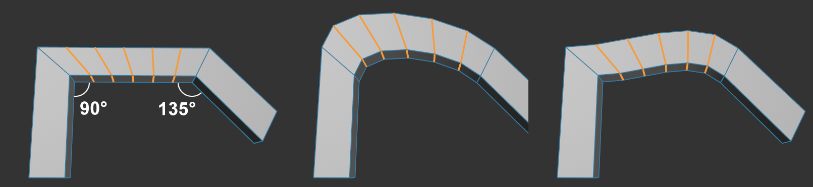 From left to right: Initial position, Maximum Angle less than 90° and between 90° and 135°. Values in excess of 135° (not shown here) will produce the initial state.
In simple terms, the angle can be used to restrict the effect of the curvature on edge loops that lie outside of the selection. As you can see in the example above, the more pronounced curvatures (at 90° and 135°) can be ignored if Maximum Angle is greater than the existing angles (at right of image).
Sets the points of the selected edges to equal distances to the neighboring parallel loops (if Strength is set to 100%) The will then lie between these in the center.
As soon as you set this option, selected edges form a plane with the neighboring parallel edges (see also Linear).
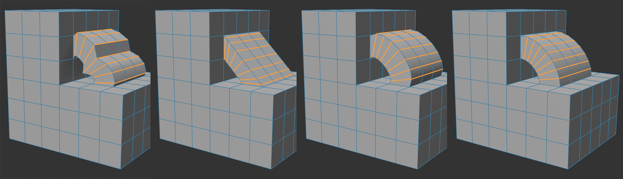 From left to right: original length, Fallback modes Off, Edge, Normals.
This mode is used when no surface curvatures of neighboring polygons can be detected. This is then the case if no fitting edge loop can be found or the Maximum Angle setting described above (e.g., for 180°) doesn't allow any. If a fitting curvature is found, this function's settings will be ignored.
The following modes are available:
-
Off: a linear progression is used.
-
Edge: the progression is based on the first and last loop of the selection.
-
Normals: the course is based on the surface Normals of the geometries adjacent to the bridge ends. If no polygons exist there - imagine everything except the bridge deleted in the image above - a linear progression will be used.