

Export
 The pure particles of the Particle Group can be seen on the left. A Liquid Mesh object has been added in the middle. The display of the particles is supplemented by a preview of the liquid geometry. In this case, the Particle Group can also be switched off completely for the editor display in order to display only the calculated surfaces. In order to be able to texture the liquid with any materials and render it, at least the Geometry option for the Export on the Liquid Mesh must be activated (can be seen on the right).
By default, the calculation of the liquid geometry is carried out on the graphics card. This ensures that the calculation can be carried out as quickly as possible and at the same time a meaningful representation is already displayed in the viewport. The principle is comparable to the Pyro Simulation, where smoke and flames can also be displayed in the views, whereby this data must also first be downloaded from the graphics card for rendering in order to be able to assign volumetric materials.
As can be seen in the middle of the figure above, the normal particles are always displayed in addition. When using a Liquid Mesh object, you can therefore actually switch off the display of the Particle Group in order to only examine the preview of the liquid.
In order to be able to texture and render the calculated geometry with any materials, the data must be downloaded from the graphics card and converted to real points and polygons. Only then will the Liquid Mesh behave like a normal generator, which can also be influenced by deformations in the scene, for example. To download the data from the graphics card, you can use the following options to select which data is actually required. For the final rendering, remember to deactivate the rendering of the Particle Group so that it is not rendered in addition to the liquid surface. To do this, simply add a Redshift Object Tag to the corresponding Particle Group and deactivate its display in the Particle category. Otherwise, particles are always rendered as a small sphere by default.
These options are available for downloading data from the graphics card:
This can be used to load the calculated polygon hull into the scene, e.g. to assign materials to the fluid simulation and render it or to apply deformations to the Fluid Mesh. This option also forms the basis for the other optional data.
If the smoothing of the normals on the Liquid Mesh has been activated, this option should be switched on so that they are also used for the surface shading during rendering.
When activated, a Vertex Map Tag is added to the Liquid Mesh object, the values of which provide information about the individual density of the particles in the corresponding area of the liquid. Normally, the density of a liquid simulation is constant, but different values can also occur if, for example, different liquids come into contact with each other.
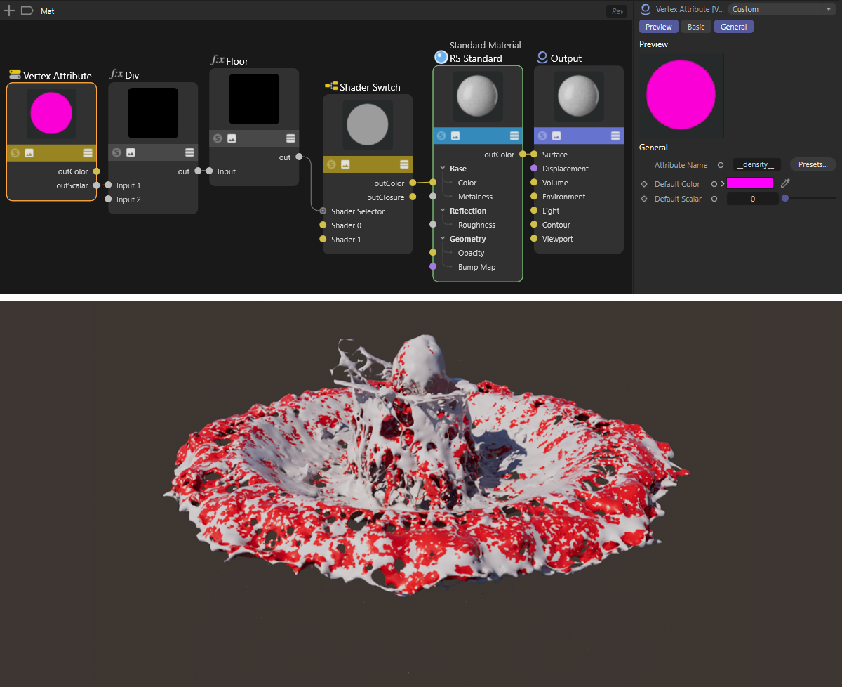 Here, two liquids with different density settings have been poured together in a bowl. By activating the Density option for the export on the liquid mesh, a Vertex Map with the name __density__ is created, which can be read out via a Vertex Attribute Node and used, for example, to switch between different color values.
When activated, a Vertex Color Tag is added to the Liquid Mesh object, whose colors then reflect the interpolated particle colors in the corresponding area of the liquid. These colors can then be read out directly in the material system and thus also integrated into your own materials. The example above in the discussion of the Density export option demonstrates how such vertex color values can be read out in a Redshift material. The default name of the Vertex Color Tag is __color__.
When activated, a Vertex Color Tag is added to the Liquid Mesh object, whose colors then reflect the interpolated particle velocities in the corresponding area of the liquid. This information can be evaluated, for example, for the calculation of deformation motion blur in a Redshift Object Tag.
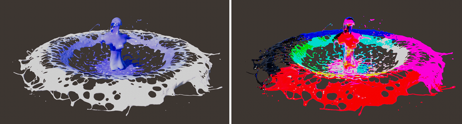 On the left, the original particles were colored according to their velocity using a particle Color Mapper modifier. By activating the Color option, this information can then also be transferred to the geometry of the liquid using a Vertex Color Tag and then read out within a material, for example. On the right, the corresponding color values can be seen, which can also be added as a Vertex Color Tag after activating the Velocity option.