

Object Properties
Here you get a picture preview of the selected plant. This preview also contains the name and scientific name of the plant. When calling up the Plant generator via >, this area is initially still empty, as the desired plant must first be selected. It is different if you load one of the parametric Laubwerk plants directly in the Asset Browser by double-clicking on it. This also creates a Plant object in which the corresponding plant is automatically loaded.
Clicking in the preview area of the Plant object opens a new Asset Browser, which automatically displays only the matching plants. In this way, the desired plant can be loaded directly into the new Plant object or an existing plant can be replaced with another plant.
To do this, double-click on the corresponding plant in the Asset Browser or select the desired plant by clicking once on the preview image and then confirming by clicking the OK button at the bottom of the Asset Browser. The following figure illustrates this selection process.
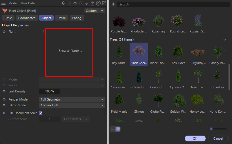 By clicking in the preview area (marked red on the left), you can select a plant in the Asset Browser (see right-hand side of the illustration) or replace an already assigned plant with another one.
Plant objects without an assigned plant can be recognized by their reddish icon in the Object Manager (see also the left-hand side of the illustration above). After assigning a plant species, the icon is displayed in green. This allows you to see at a glance in the Object Manager whether all Plant objects actually represent a geometry.
The icon is also colored red if, for example, a path entered for a plant cannot be found. This can happen, for example, if you already owned the Laubwerk plugin before it was integrated into C4D 2025.3 and had also purchased the corresponding Plant libraries separately. If such an older scene is opened and the plants have perhaps been copied to another folder or even deleted in the meantime, they can no longer be found. In such cases, please read here how you can continue to use and import separately purchased Laubwerk libraries.
In this context, it can also be helpful to specify a default directory for Laubwerk libraries in which the Plant Object should always look if a specified plant path cannot be found. You can find more information about this default setting here.
The plants are generally generated on a realistic scale and therefore do not normally need to be scaled manually. This may only be necessary if you have not designed the other components of the scene in realistic dimensions or if you deliberately want to provide even more variation when using the same plant species by means of additional scaling.
To the left of the preview image you will also find an arrow symbol which you can use to view the path to the selected plant and, if necessary, edit it by selecting a different file. The folder icon to the right of the path line is available for this purpose.
In each case, selecting a different plant results in the properties already set for the previous plant being adopted. Properties such as Model variation, growth phase, Season or Leaf Density therefore do not need to be reconfigured.
Each selected plant species is generally available in several form variants, which in turn are often available in different growth phases, such as Young, Middle-Aged and Full-Grown. For deciduous and coniferous trees, for example, three shape variants are generally offered, each with three growth phases, resulting in nine different models per plant species.
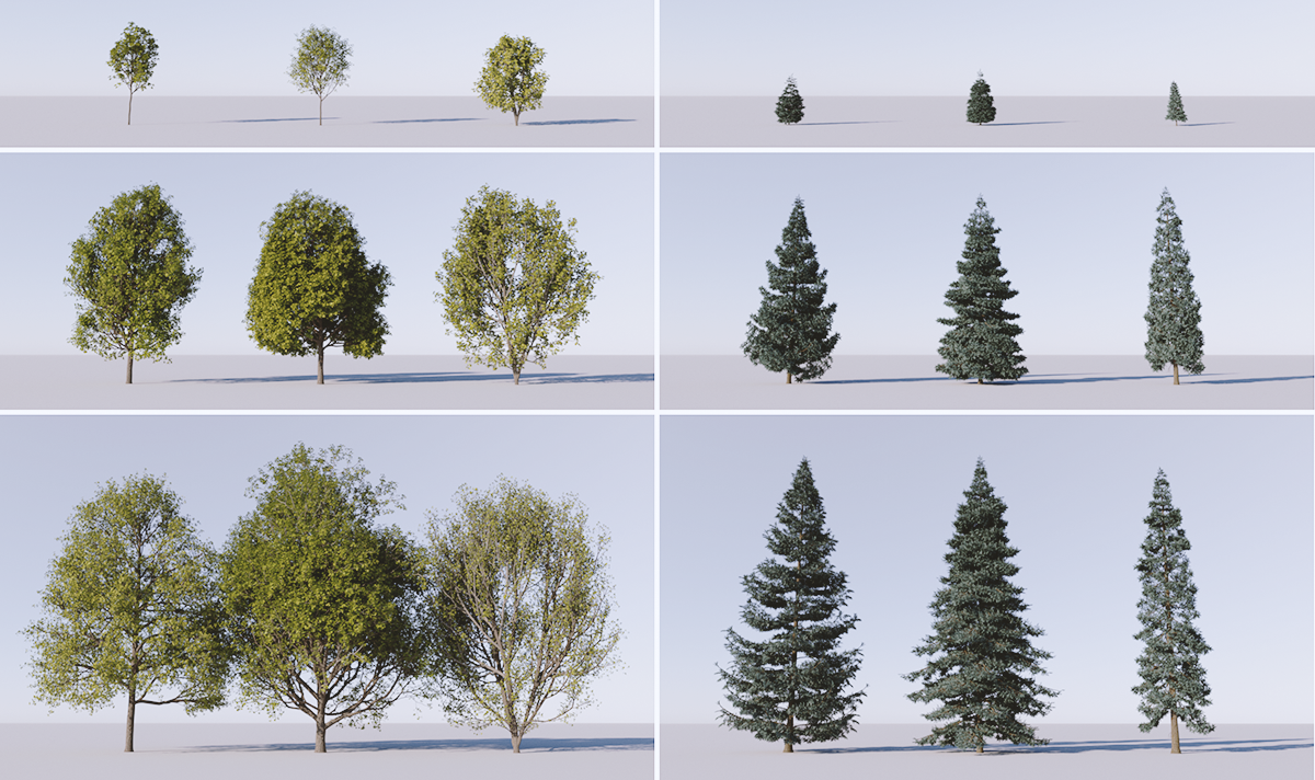 Each plant can be produced in several growth stages and shape variations. These variations are shown on the left for a deciduous tree and on the right for a conifer. The variants and growth phases are different for each plant species.
The following illustration shows an example of the flexibility of this setting for a simple grass, for which only a middle-aged growth phase is offered, but this is offered directly in six different variants.
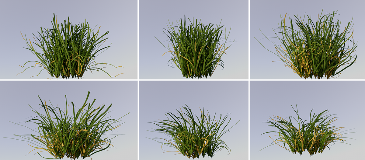 These pictures show an example of a grass plant for which only one middle-aged growth phase is offered, but in six different variations.
In any case, the Model setting allows you to place several plants of the same species close together without the plants looking too similar. Additional variations can also be achieved by rotating the models around the vertical, as this allows the viewer to see different perspectives of the plant. Settings are also available for individual adjustment, e.g. of the Leaf Density or a Custom Scale.
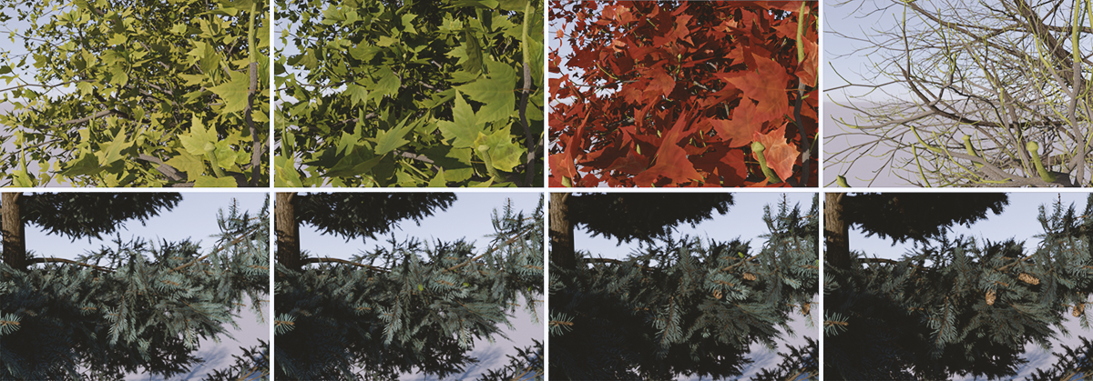 In the top row, from left to right, the seasons Spring, Summer, Fall and Winter are shown as examples for a deciduous tree. The series of pictures below shows these seasons for a pine tree.
The desired season for the plant can be selected here. This influences the number, size and coloration of the leaves, especially in deciduous trees. The changes during the seasons are less pronounced in conifers. In addition to a change in the color of the needles, additional details such as the growth stages of cones in Autumn and Winter are particularly striking.
Depending on the plant species selected, other variants may also be available, such as tropical plants, where the annual cycle tends to be divided into Rainy Seasons and Dry Seasons. The following series of images provides an example. There you could choose between early and late rainy season, as well as early and late dry season. However, there are also plants for which no season can be changed at all, such as some grasses that look the same all year round.
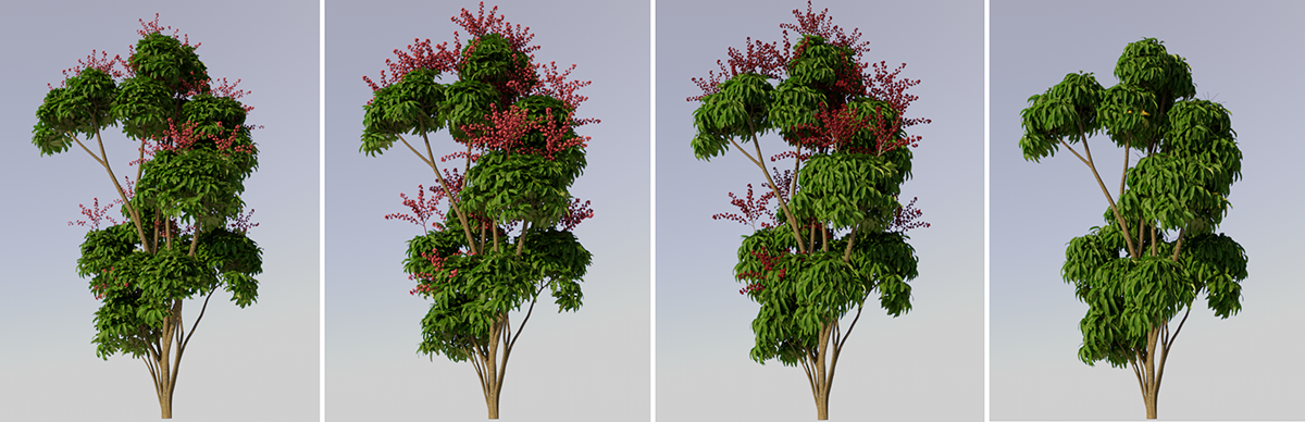 Exemplary variation of the seasons for a tropical tree. From left to right, the early and late rainy seasons and the early and late dry seasons are juxtaposed here.
The number of leaves or needles on a plant can be individually adjusted using this percentage value. This can be used, for example, to improve the visibility of a background or to save memory for leaf and needle polygons. It can also be used to indicate seasonal transitions, such as the time between winter and spring on deciduous trees.
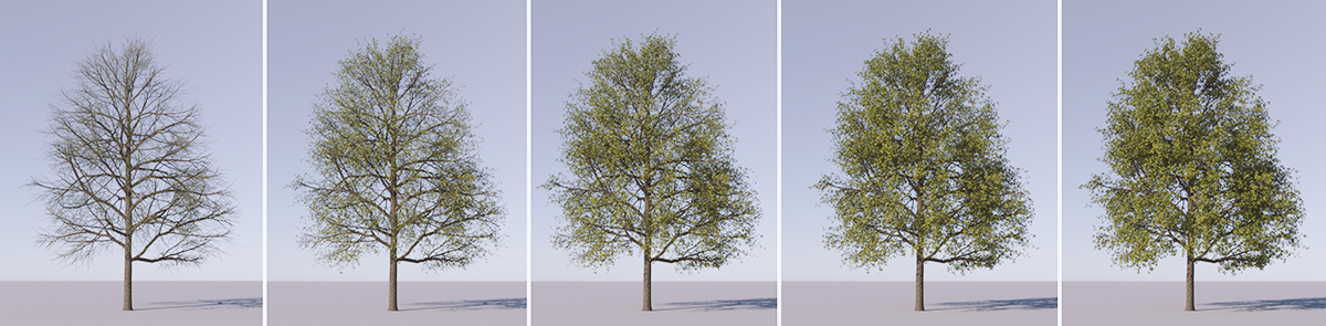 From left to right you can see the change in Leaf Density on a deciduous tree between 0% and 100%.
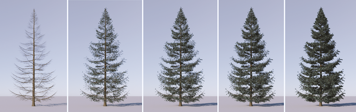 From left to right you can see the change in Leaf Density on a conifer between 0% and 100%.
This effect can be used, for example, for plants placed further away from the viewer, as fewer leaves or needles on a plant also mean a corresponding reduction in the memory requirements for this plant. This setting is also helpful for plants at close range, for example to reduce the subject coverage of a tree crown and make more of the background visible again.
In the Detail settings of the Plant Object, you will find a comparable Leaf Amount setting. This can also be used to reduce the number of needles or leaves, but the remaining leaves are enlarged at the same time in order to keep the visible volume of the plant as constant as possible.
Here you select how the plant is to be used during the final image calculation. A comparable Editor Mode is also available, with which the level of detail of the plants in the view windows can be controlled separately.
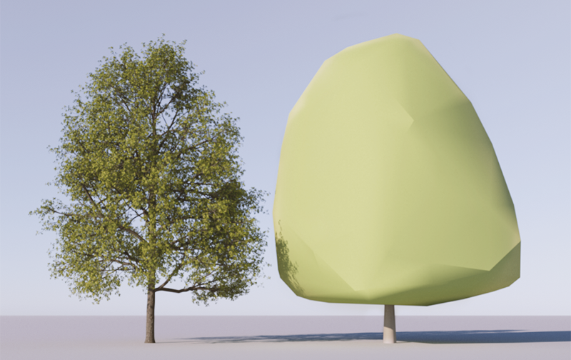 On the left the full Render Mode, on the right the abstracted representation as a Convex Hull.
Please note that even when rendering directly within the views, only the Editor Mode quality of the plants is rendered. The Render Mode is only used when rendering in the Picture Viewer or the Redshift RenderView. For an unreduced display of the plants during test renderings directly in the views, the Editor Mode must therefore be switched to Full Geometry beforehand.
These options are available:
- Full Geometry: All details and the best quality of the plant geometry are calculated. This is usually the correct setting for the final rendering of your project.
- Convex Hull: Only a highly abstracted and simplified version of the plant geometry is calculated. The materials are also reduced to simple color values. Since even in this version the size and shape of a plant can still be estimated well, this representation is suitable for quick test renderings, which also require very little memory. This representation can also be used for illustrative representations, e.g. of forests.
This is where you select how the plant is to be displayed in the editor views. A reduced level of detail compared to the Render Mode helps you to continue to navigate smoothly in the views and place plants, especially in projects with many plants and detailed models.
Note that this setting is only available if Full Geometry Render Mode has been selected. Otherwise, the Convex Hull is also automatically used for the Editor Mode.
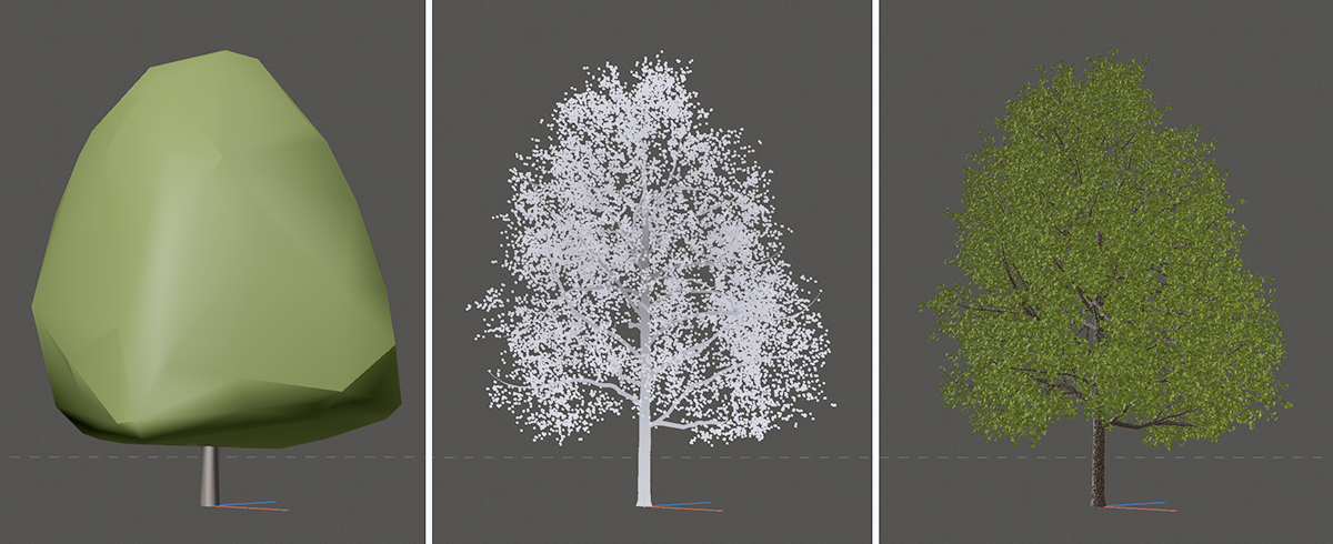 On the left the editor representation of the Convex Hull, in the middle the Skeleton representation, on the right the complete Render Geometry with all polygons.
These levels of detail are available for the editor display:
- Convex Hull: This is the simplest type of representation for plants, which nevertheless provides sufficient information about the basic shape and size of a plant. Only a highly abstracted and simplified version of the plant geometry is displayed. This mode is good enough if you only want to place the plants in the scene without necessarily having to see all the details. This puts the least strain on the speed of the editor view.
- Skeleton: Although the materials are not shown and the leaves are only represented by simple dots, the exact shape of the plant can be estimated very well. Compared to the Full Geometry display, this saves memory and also enhances the navigation speed somewhat. Please note, however, that the plant cannot cast a shadow in the view in this display quality.
- Full Geometry: All details and the best quality of the plant geometry and materials are calculated and displayed. You will receive the same geometry that is displayed in the final rendering when you select Render Mode Full Geometry.
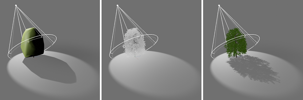 From left to right, the Editor Modes Convex Hull, Skeleton and Render Geometry. Neither materials nor shadows can be displayed in the editor for the Skeleton display.
All plants are automatically available in realistic size and do not normally have to be scaled manually. When activated, this option ensures that the plant size is automatically scaled to the unit of measurement currently used in the project (see Edit>Scene Settings>Project Scale). If, for example, Centimeters are used as the unit of measurement, the plant is automatically scaled correctly in this unit. Only if you want to adjust the plant size manually can you deactivate this option and use the Custom Scale value below.
This setting is only available if Use Document Scale has been switched off and then allows you to influence the plant scale yourself. The Custom Scale value functions like a multiplier. If you use e.g. 1 centimeter as the Project Scale in the Scene Settings, the 2 Centimeters Custom Scale can be used to halve the plant size. Every centimeter within the scene is therefore practically considered to be two centimeters and the plant is therefore only half the size.
Switching the unit of measurement behind the Custom Scale value can have an even more dramatic effect on the plant size. Switching from Centimetres to Meters (if Centimetres are used as the Project Scale unit) then results in the plant having only one hundredth of its original size, for example. One hundred centimeters on the plant becomes one centimeter in the scene.
Info area
Here you can view statistics on the selected plant and its editor geometry. This includes the number of points and the number of polygons for the Convex Hull and the Full Geometry. If you have selected the Skeleton Editor Mode, no polygons are generated for this. You can therefore only read the lines and points generated for the display here.
The Info area is therefore comparable to the Object Information that can be called up via the Object menu in the Object Manager. The number of points and polygons of a selected object and the resulting memory requirements can also be displayed there, for example.
You can use the info area, for example, to check the savings in the number of dots and polygons when reducing the Leaf Density or Subdivision (see Detail settings). This is particularly helpful if you are using the Full Geometry for the Editor Mode, as the values displayed are then identical to those generated for the external rendering (see Render Mode).