

Properties

These settings define how long the Liquid FX particles exist. They only take effect if Limited is enabled. In addition, the lifetime of each particle type can be shortened individually with the Lifetime Decay values in the Spray, Foam and Bubbles sections.
This option is enabled by default and limits the lifetime of the particles. The lifetime is then defined by the following Expectation setting and by the Lifetime Decay values of the three particle types. If you disable this option, all lifetime settings lose their effect and the particles are no longer deleted automatically. In any case, the lifespan can still be influenced after emission, e.g., via modifiers or a Destructor Force object.
This value, measured in frames, specifies the period of time after which the particles should be automatically deleted. This time period used applies from the moment a particle is created. The lifetime can also use a Variance that gets applied randomly per particle. In addition, the lifetime of the particles can be individually extended or shortened by modifiers even after emission.
For Liquid FX particles, how quickly this lifetime is used up also depends on the Lifetime Decay value of the respective particle type.
This value given in frames can be used to randomly vary the life expectancy of the particles. This can result in an extension or shortening of the original Expectation by a maximum of the entered value for each particle. Like all variation values, this setting is also based on the Seed value of the emitter. A new Seed value therefore also results in a redistribution of the Variance for the length of the life span of the particles.
This percentage value controls the adoption of the lifetime of the liquid particle from which a Liquid FX particle is emitted. At 100%, the current lifetime of the source liquid particle is completely adopted and the Expectation settings lose their effect.
Spray particles have only a few liquid particles as neighbors, for example drops that fly through the air. They simply move by inertia. As soon as they come close to the liquid again, they usually turn into foam.
Defines how quickly spray particles use up their lifetime. Higher values shorten the lifetime of these particles, lower values extend it. This value only takes effect if Limited is enabled in the Lifetime section. Since spray particles quickly turn into foam or bubbles anyway, this value is the most effective way to control the amount of visible spray: Lowering it keeps spray visible for longer and can increase the amount of spray considerably, while the amount of foam and bubbles remains largely the same.
Foam particles float on the surface of the liquid. They are drifted by the surrounding liquid and stay at a specific offset from the surface. Foam is created, for example, when spray falls back onto the liquid or when bubbles reach the surface.
Defines how quickly foam particles use up their lifetime. Higher values shorten the lifetime of these particles, lower values extend it. This value only takes effect if Limited is enabled in the Lifetime section.
Specifies how much the movement of the foam particles is influenced by the surrounding velocity of the liquid. At 100%, the foam follows the flow of the liquid surface. Lower values let the foam react less to the movement of the liquid.
Use this value to randomly vary the Drift per particle. The value can deviate from the Drift by up to the entered value. Like all variation values, this setting is based on the Seed value of the emitter.
Defines the distance between the foam particles and the liquid surface. The value is a multiplier of the average radius of the neighboring liquid particles at the surface, so at 100% the foam floats at a distance of roughly one particle radius. Higher values raise the foam as a whole. Note that this does not result in a thicker layer of foam, because the foam always remains coupled to the liquid surface.
Use this value to randomly vary the Surface Offset per particle. The value can deviate from the Surface Offset by up to the entered value. Like all variation values, this setting is based on the Seed value of the emitter.
Bubbles are located inside the liquid. They are drifted by the surrounding liquid and additionally experience buoyancy, so they rise to the surface. When they reach the surface, they turn into foam.
Defines how quickly bubbles use up their lifetime. Higher values shorten the lifetime of these particles, lower values extend it. This value only takes effect if Limited is enabled in the Lifetime section.
Specifies how much the movement of the bubbles is influenced by the surrounding velocity of the liquid. At 100%, the bubbles are carried along by the flow of the liquid. Lower values let them react less to the movement of the liquid.
Use this value to randomly vary the Drift per particle. The value can deviate from the Drift by up to the entered value. Like all variation values, this setting is based on the Seed value of the emitter.
Defines the upward force that acts on the bubbles and simulates their buoyancy. Higher values let the bubbles rise faster, so they reach the surface sooner and turn into foam there.
Use this value to randomly vary the Buoyancy per particle. The value can deviate from the Buoyancy by up to the entered value. Like all variation values, this setting is based on the Seed value of the emitter.
These settings define how the Liquid FX particles behave when they collide with objects of the simulation.
Turns the collision detection of the Liquid FX particles on or off. If it is enabled, the particles react to static objects with a Collider tag as well as to objects that have received dynamic simulation properties, e.g. via a Rigid Body, Cloth or Rope tag. How the particles behave on contact is defined by the following settings. If the option is disabled, the particles pass through these objects without reacting to them.
Defines the mass value of the Liquid FX particles that is used in collision interactions. Together with the speed of the particles, it determines the force the particles can exert on other dynamic simulation objects, such as rigid bodies or cloth.
Defines the friction applied to the Liquid FX particles during collisions, i.e. how much they are slowed down when they slide along a surface. As with liquid particles, the effect also depends on the Friction value of the colliding object, e.g. on its Collider tag.
Defines how strongly the Liquid FX particles stick to surfaces upon impact. As with liquid particles, the effect also depends on the Stickiness value of the colliding object, e.g. on its Collider tag. If one of the two values is 0, the particles cannot stick to the surface.
These settings define the initial velocity of newly emitted Liquid FX particles.
This percentage value controls the adoption of the velocity of the liquid particle from which a Liquid FX particle is emitted. At 100%, new particles start with the full current velocity of their source liquid particle. Lower values let them start more slowly.
Defines the angular spread of the particles upon emission, i.e. the maximum angle by which the direction of movement of a new particle can randomly deviate when it is emitted. Higher values make the particles fan out more strongly, for example to create a wider spray.
In this area, you define the start color of the particles and their Alpha value. This Color is read out automatically, e.g. by the MoGraph Cloner or the Redshift Object Tag. In addition, this particle color can also be read directly via a Color User Data Node in Redshift materials. The Alpha value of the particles can be read out separately via a Scalar User Data Node.
Here you can select how colors are to be generated and assigned to the particles:
- Constant: The values set with Color and Alpha are assigned to all particles. This is the default setting.
- Random: In this mode, an individual color gradient with colors and alpha values can be defined. The colors and alpha values are then read out randomly from this gradient for each particle.
- Noise: This mode works in a similar way to Random and also uses an individually configurable color and alpha gradient. This time, however, the assignment of colors and alpha values is not purely random, but based on common noise patterns and can therefore also be configured with transitions.
In Constant Sample Mode, select the color value that should be assigned to all particles when they are created. Click on the arrow symbol next to the color field to access the standard color controllers and color selection systems. Alternatively, different color selectors can also be displayed in a separate dialog box when clicking directly on the color field.
The pipette symbol to the right of the color field also allows you to pick up a color value directly from another location on your monitor with a simple left-click. This color recording mode can also be ended early by pressing the Esc key.
In Constant Sample Mode, select the alpha value that should be assigned to all particles when they are created. This property is not displayed directly on the particles in the viewports, but can be read out, for example, within Redshift materials with the Scalar User Data Node and its Particles/Transparency (XP) preset and thus also used to control material properties. Its use is not limited to specifying the color opacity, but can also control the roughness of a reflection or the intensity of lights, for example. This is because an Alpha value represents regular floating point values between 0 and 1 (or converted values between 0% and 100%).
This element is offered in the Sample Modes Random and Noise and lets you define several color and alpha values from which the particles are then selected randomly or based on a noise structure. The color gradient used for this is also used as a control element in many other places in Cinema 4D. If you would like to read about its functions again here, simply open the following section.
 Click here to unfold the description of the gradient UI element in Cinema 4D.
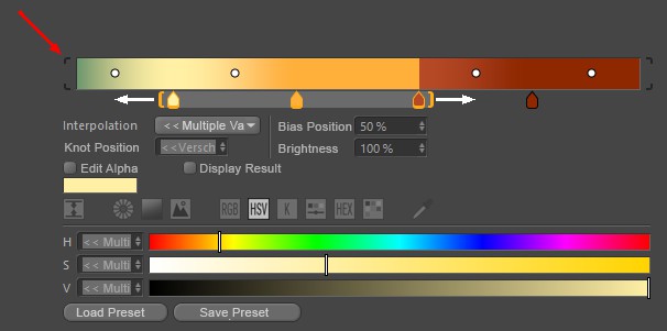
Gradients are used at many locations in Cinema 4D and make it possible to use color and alpha values to create linear gradients that run from left to right. Various types of interpolation are available, which can also be used to calculate automatic transitions between the colors and alpha values you have placed. Note that you can access further parameters (described below) by clicking on the small arrow to the right of the color gradient.
The small, square color fields directly below the gradient (called Knots) determine the colors and their positions in the gradient. To add a new Knot, simply place your mouse pointer just below the gradient. A semi-transparent color tab appears, which can be moved sideways together with the mouse pointer. A click then creates a new color tab. To remove excess color tabs from the gradient, simply drag them up or down out of the gradient with the mouse.
To change the color of a color tab, select it by simply clicking on it. Below the gradient, settings for the exact position of this color on the gradient, the interpolation used on this tab to the neighboring color on the left and, of course, the standard color sliders for adjusting the color are displayed. Some interpolation types also offer additional Knots on the gradient, which are visible as small circles between the color tabs. This can be used to change the mixing point at the color transition between the colors. These Bias Handles can also be moved directly with the mouse or placed with numerical precision by simply clicking on a numerical value for the bias position.
If you also hold the Shift key when moving color, alpha or Bias Handles, the movement will be performed in 5% increments.
Several Knots can also be selected at the same time. To do this, you can select the Knots one after the other using Shift + click (or remove them from the selection again using Ctrl-click) or hold down the left mouse button directly in the color gradient and drag a selection frame over the desired Knots from there. Orange brackets appear around the selected Knots below the gradient. All Knots contained in such a bracket can be moved together along the course if you place the mouse pointer between the brackets and then drag them with the left mouse button held down. Pulling on the Knots will scale the distances between the Knots within the brackets. The colors cannot be placed outside the boundaries of the gradient. If you move a group of color tabs too far to the left or right, the outer color tabs will automatically stop at the edges of the gradient and their distance to the subsequent colors may be reduced as a result.
Similarly, the bias Knots can be selected in groups and then moved together. However, no separate Knot symbols will be displayed. Selected Bias Handles can be recognized by the black coloring, whereas unselected Knots use a white circle as a symbol.
A double-click in the color gradient selected all Knots, a single click deselects everything. Double-click on a Knot to display all settings in a separate window. If there are several Knots on top of each other, they can be right-clicked to select one of them from a list that appears (selected Knots are enclosed in square brackets).
The gradient can be moved or scaled horizontally (see below). In the latter case, brackets appear around the color gradient (red marking at the top of the image). Clicking on these brackets scales the color gradient back to 100%.
Selected Knots can also be moved using the cursor keys (left, right). Shift also quantizes in 5% steps here. The cursor up and down keys adjust the Knot brightness (old color gradient only).
The following buttons apply for navigation within the color gradient - similar to the Timeline:
- 1, Middle mouse button: Move (only possible with enlarged color gradient)
- 2, Mouse wheel, Alt + right mouse button: zoom in and out
- S: Show selected
- H: Show all or scale to 100%.
Right-click on the color gradient to open a context menu with the following commands:
Invert Gradient
This reverses the color gradient and thus the order of the colors.
Double Knots
This defines the current color gradient to its own end, doubling the Knots and the color gradient.
Distribute Knots
This sets the Knot distances to identical values.
Bias Handle
If Bias Handles (the small circles in the color gradient) are to be displayed, this option must be activated.
Interpolation of all Knots
This lets you set the interpolation of ALL Knots - regardless of the selection - at the same time.
Size
This can be used to define the vertical size of the color gradient in 3 stages. This setting is also available as a program default setting (Units tab).
Interpolation
Several interpolation methods are available to control the behavior of the color values between the Knots. Each Knot can have its own interpolation!
Soft/Cubic/Cubic Bias/Linear/Step/Blend
The color transition from one selected Knot to the next takes place as indicated by the small curve symbols in front of each option. Most interpolation types also use the Bias Handles to place the color transition between the adjacent colors as desired. Only with Step interpolation will there be no Bias Handles, as the color change will always take place abruptly when the next color Knot to the right is reached.
Step
There is no interpolation at all. The color changes abruptly without transition at the position of the next touch.
Knot position
The position of selected Knots can be defined numerically here. 0% = left edge, 100% = right edge.
Bias position
This parameter defines the position of selected Bias Handles between the adjacent colors. 0% = left color or alpha Knot, 100% = right color or alpha Knot.
Brightness
Brightness can also be used to control the brightness of selected Knots above 100%. They generate overbright colors (HDR) that the color selector cannot provide on its own.
Edit Alpha
Activate this option to work on the alpha values associated with the color gradient. The creation, placement and setting are carried out in the same way as already described for the color Knots. The only difference is that only percentage values and therefore no colors can be assigned for the alpha Knots via a Brightness value. The curve interprets 0% as black and 100% as white. Values between 0% and 100% are often used here by default, but brightness values above 100% can also be assigned.
The alpha Knots can be placed completely independently of the colors. Therefore, all color Knots and their gradients are also hidden by default in this mode.
Display Result
This option displays the color gradient taking the alpha channel into account. This means you can practically display the opacity of the alpha Knots overlaid with the colors while you work on the placement and values of the alpha Knots.
Load Preset
Save Preset
Color gradients can be saved and reloaded at any time using these two commands.
When the Save Preset command is executed, a small dialog window will open where the preset name and other information can be entered.
Click on Load Preset to open a small selection window where you can load the corresponding preset with a single click. There you will already find a selection of common color gradients, even if you have not yet saved your own.
General details regarding the Preset System in Cinema 4D can be found there.
This percentage value controls the adoption of the Color of the liquid particle from which a Liquid FX particle is emitted. At 100%, the current Color of the source liquid particle is completely adopted and the individual Color settings above lose their effect.
These settings define the size of the Liquid FX particles.
Here you can select how the radius of the new particles is defined:
- Inherit: The radius is adopted from the liquid particle from which a Liquid FX particle is emitted. The Inheritance value defines the percentage of this radius that is used. This is the default setting.
- Override: All new particles receive the fixed Radius defined below, which can be varied with its Variance.
This value is only available with Source Override.
This regulates the scaling of the particles. The size of the particles can also be displayed directly in the editor if you have activated the option to draw the radius in the Particle Group. The Radius of a particle is also automatically used for scaling the shapes that are bound to the particle via a Redshift Object Tag, for example.
The Radius can also be varied per particle during emission with the following Variance value. It is also possible to adjust the Radius at any time using various particle modifiers.
Here you can define a maximum deviation from the defined radius per particle. Negative radii will automatically be avoided for the particles. Particles can therefore never have a negative radius.
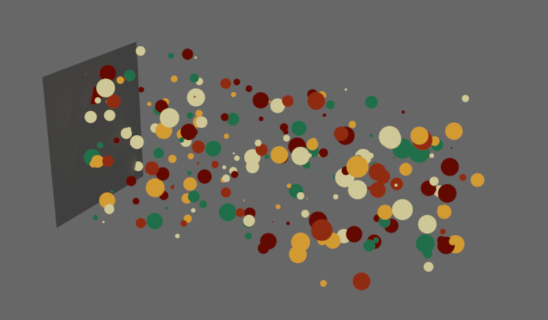 Here, a Radius of 1 was combined with a Variance of 5. This results in particles with sizes between 0 and 6.
This value is only available with Source Inherit. This percentage value controls the adoption of the Radius of the liquid particle from which a Liquid FX particle is emitted. At 100%, the new particles have the same radius as their source liquid particle.
Use this value to randomly vary the Inheritance per particle. The value can deviate from the Inheritance by up to the entered value. Like all variation values, this setting is based on the Seed value of the emitter.
These settings are only used in the Noise Sample Mode. The selected Noise pattern generates black and white values that are used to read the matching entries from the color gradient. With a black section in the Noise, the colors and alpha values from the left edge of the color gradient are used for the particles; with white Noise, the colors and alpha values from the right edge of the gradient are used. Gray intermediate values address corresponding sections in the middle part of the gradient.
This option must be switched on so that a Noise structure is used to determine the color and alpha values of the color gradient. If this option is switched off despite the selection of Sample Mode Noise, all particles will receive the same color from the left edge of the gradient.
The calculation of the Noise pattern is based on this value. A change in the Seed value therefore also leads to a recalculation of the selected Noise structure.
Here you can choose the right one from the various patterns. These are three-dimensional structures that can be configured in the axis system of the emitter or the world and with individual scaling along all axis directions. Automated modification and animation of these patterns is also possible:
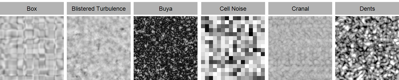
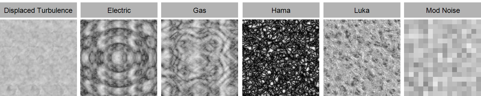
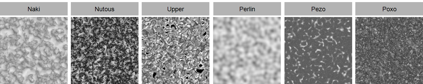
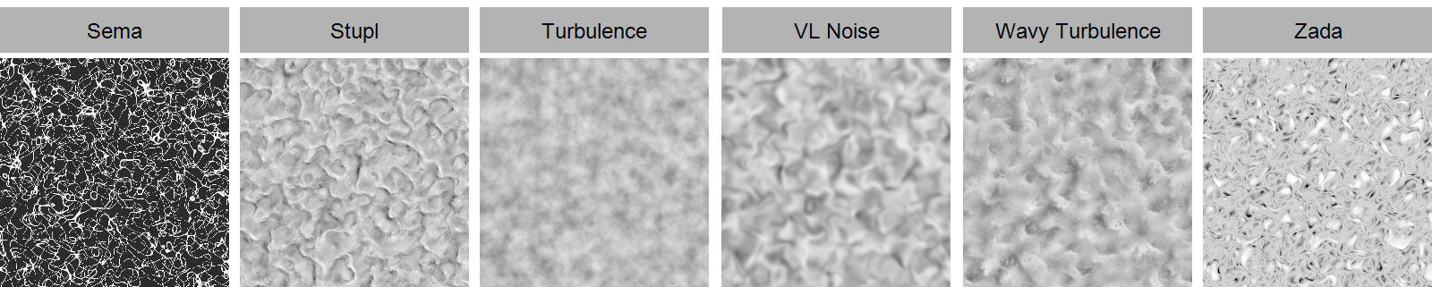
Here you can select whether the Noise structure should move with the axis system of the emitter or whether it should be a stationary Noise whose origin lies in the global world axis system.
This defines the amount of detail in the Noise structure. Larger values produce more variations in the Noise pattern. Small values lead to a loss of contrast and details, as well as to a softening of the structure. This setting is not available for the Noise Types Box, Cell, Mod Noise, Perlin and VL Noise.
You can use these values to scale the Noise structure individually along the three spatial directions. Proportional scaling is also possible via the separate Scale value.
This allows the Noise structure to be scaled proportionally. Individual scaling for each of the three axis directions is also possible using the separate Relative Scale.
The Noise structures can also be changed over time. Use this value to specify the speed of these changes. By default, 0 is used here, which results in a static structure.
Almost all Noise types (exception: Electric and Gaseous) have this parameter, which causes the noise to loop after the specified time in seconds (the Animation Speed must be greater than 0). The Noise state then repeats itself in the bars of the Loop Period, which is specified in seconds. A value of 0 turns this effect off.
These two parameters are used to move the Noise through the 3D space. Movement is used to set the direction in which the Noise structure is moved. Use the Speed value to regulate the movement speed of the Noise structure.
Please note that the Movement is also dependent on Noise Space, as the coordinate systems defined there can differ greatly from one another.
This can be used to limit the brightness values that the Noise should provide. By default, Low Clip is 0% and High Clip is 100%. This means that all brightnesses can be output unchanged between 0% and 100% by the Noise. Increasing the Low Clip results in all brightnesses that are lower than Low Clip being output as black (or 0%). Similarly, a reduction of High Clip results in all gray values above the brightness of High Clip already being output as white (or 100%).
In fact, this mechanism can be used not only to sharpen a Noise structure and to strengthen the contrast, but also to invert the brightness values. To do this, simply reverse the original arrangement of the clipping values. With Low Clip 100% and High Clip 0%, you get an inverted noise.
This is used to adjust the general brightness value of the Noise. Values above 0% increase the brightness, values below 0% reduce it.
This allows us to reduce or increase the contrast of the Noise brightnesses. The Contrast describes the range of brightness values output. With a low contrast, the differences between the Noise brightnesses supplied are therefore smaller. Greater Contrast leads to greater differences in brightness between the Noise brightnesses calculated. This often results in the brightness transitions being more abrupt and less smooth compared to using a lower Contrast.