

Object
Output particle properties relating to distances or positions will be converted internally with the unit [m], i.e., as meters. This can, of course, have a major impact on the result. An X position of 90 cm, for example, will become the value 0.9 m when output.
Here you can select the particle Property that you want to change using the Modifier. These selection options largely correspond to those in the Properties menu, which can be used to read out individual properties of the particles:
- Age: The age of the particles measured in frames.
- Angular Velocity: The rotation axis of the particle rotation can be defined individually as a direction vector via the global vector components X, Y or Z.
- Color: The red, green, blue or alpha components of the particle colors can be defined individually.
- Distance Traversed: This is the distance a particle has traveled since it was created.
- LIfetime: This defines the maximum Lifetime of the particles.
- Position: The global position of the particles can be defined individually for the X, Y or Z components.
- Radius: The Radius property of the particles.
- Velocity: The flight direction of the particles can be defined separately for the global X, Y or Z direction.
- Custom: If you have created your own properties for the particles in the Scene Settings, you can select them here and assign different values to them. Alternatively, user properties created on particles can also be used, for example, with Color Mapper or Data Mapper modifiers or with the Get Custom Particle Property Node, which can then be used within the Particle Node Modifier.
Please note that the values may be converted if the data types are not identical. For example, floating point values that are assigned to an integer user variable are always rounded to the nearest integer value.
Some properties are already automatically available when processing liquid particles: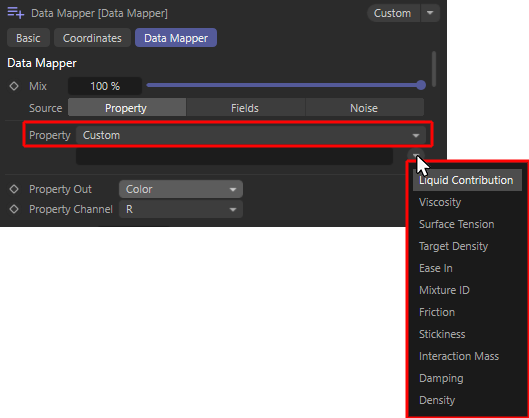 When using liquid particles, their most important properties are automatically available as user properties (demonstrated here using the example of a Data Mapper Modifier).
These special properties can be used to change a liquid over time, for example, or to keep it dependent on other properties of the simulation. Liquid particles can be generated directly with the Liquid Fill Emitter or by converting standard particles with a Liquify modifier. Please note that many of the user properties listed below can also be changed at any time using a Liquify modifier.
These properties are automatically available for this purpose:- Liquid Contribution [Floating Point]; This value is between 0 and 1 and indicates whether a particle only has to adhere to the forces, conditions and modifiers of the particle simulation (value = 0) or whether it is a liquid particle (value = 1) for which additional forces, such as gravity and forces between neighboring liquid particles, apply. By changing this value, particles can therefore switch continuously between the properties of "normal" particles and the properties of liquid particles.
- Viscosity [Floating Point]: This value describes the flow resistance of the liquid. Small values make a liquid appear watery and thin, higher values make the simulation appear viscous and honey-like.
- Surface Tension [Floating Point]: This describes the Surface Tension of the liquid. With increasing values, the liquid particles tend to clump together more strongly. This can be used, for example, to obtain larger individual droplets. It should be noted that this property also depends on the existing particle density (Target Density).
- Target Density [Floating Point]: This describes the particle density per unit volume that the simulation should achieve as far as possible. A higher particle density per volume has an effect in combination with other dynamic simulation objects, for example. A liquid with a higher density can then exert a stronger force on clothing or rigid body objects.
The forces acting between the liquid particles also depend on this density. If more particles are drawn together in the same space, the surfacetension can also show stronger effects. In addition, within the same simulation, a liquid with a lower density will always float on a liquid with a higher density, just as oil floats on water, for example. - Ease In [Floating Point - Time]: This value specified in simulation images describes the time it takes for the particles to change from normal particle properties, e.g. specified by the emitter and influenced by particle modifiers, to characteristic liquid properties. Since pure liquid particles can react extremely to overlapping radii during formation at the emitter, for example, this transition time can be used to mitigate the repulsion of colliding liquid particles at the emitter.
- Mixture [Index]: All particles with the same Mixture ID value are simulated as one liquid. Liquid particles with different Mixture ID values can no longer be mixed freely and therefore remain separate from each other within the simulation.
- Friction [Floating Point]: This value relates to the interaction of the liquid with collision objects, e.g. objects that have a Collider Tag. The value then describes the energy loss due to friction that the liquid suffers during contact with the collision object. Please note that the actual friction and the actual energy loss are also influenced by the Friction value on the Collider Tag. The friction of the liquid is only taken into account if the collision object also has friction.
- Stickiness [Floating Point]: This value relates to the interaction of the liquid with collision objects, e.g. objects that have a Collider Tag. The value then describes the stickiness of the liquid to the collision object. Please note that the stickiness is also influenced by the Stickiness value on the Collider Tag. The Stickiness of the liquid is only taken into account if the collision object also has Stickiness values above 0.
- Interaction Mass [Floating Point]: This value specifies the mass of the fluid particles. The mass plays a role above all in the interaction with other dynamic simulation objects, because together with the speed of the particles, this results in the force that the particles can exert. Particles with a larger mass can, for example, deform simulated substances more strongly or move rigid bodies more easily.
- Damping [Floating Point]: This percentage value describes the energy loss within the fluid simulation. The greater the damping, the slower the fluid particles move and the faster strong accelerations are reduced. Damping can therefore prevent the simulation from 'exploding', but also leads to a strongly decelerated and unnatural behavior of the fluids if the values are too high, which in extreme cases can then be completely frozen.
- Density [Floating Point]: This value is only intended for the output and can therefore not be written to the liquid particles. This is the current density of the liquid in the vicinity of the respective particle. For particles in the core area of a liquid, this value should therefore be relatively close to the desired Target Density.
The effect of these properties on the liquid simulation can be read in the description of the Liquid Fill Emitter, among other things.
The following properties only affect the velocity of the particles:
- Rotation Speed: Sets the amount of rotation speed of a particle as an angle per second. The position of the Rotation Axis can be defined as a separate property.
- Airspeed: This sets the amount of airspeed of the particles per second. The Flight Direction can be defined as a separate property.
Some of the properties to be influenced are vectors that can only be changed by the Modifier for one component at a time. This applies to these properties:
- Color: You can selectively set the R, G and B components of the color or just the alpha component of the color (A).
- Position: Select whether the X, Y or Z component of the global position should be affected.
- Angular Velocity: Select whether you want to define the X, Y or Z component of the direction vector in global coordinates that describes the new rotation axis of the particles.
- Angular Velocity: Select whether you want to control the global X, Y or Z part of the flight direction.
- Angular Velocity Speed: Select the axis direction for which the rotation speed should be changed here.
- Velocity Speed: Select the axis direction along which you want to set a new airspeed.
- Custom: If the selected user property has a vector data type, the individual components of a color or vector, for example, can be selected here.
Here you select which value you want to use as the basis for the calculation:
- Constant: You define a Value that is offset against the output parameter using the selected Function. Existing particle properties will not be included.
- Fields: Use Field Objects to create values which are then multiplied by the Value and offset against the output parameter using the selected Operation.
- Property: Here you can read out an existing particle Property and multiply it by a Value. The result will be offset against the output parameter using the selected Operation.
- Random: A random value is determined for each particle, which is also based on the Seed value and whose order of magnitude lies between the specifications for Minimum Value and Maximum Value.
Please note that even with the Source settings Constant, Fields or Property, a random deviation can always be added by the Variance value.
Output particle properties relating to distances or positions will be converted internally with the unit [m], i.e., as meters. This can, of course, have a major impact on the result. An X position of 90 cm, for example, will become the value 0.9 m when output.
Also bear in mind that all calculations will be carried out again in each animation frame. Even small changes to one value can lead to stronger effects over several frames. In order to control this permanent change of particle properties more finely, Conditions can be used, for example, to apply Modifiers only in a certain range of the animation or at a certain phase of the particle's life.
Here you will find many typical mathematical calculation types, e.g., for adding, multiplying, inverting or calculating a sine value. Depending on the Source selection, there are various options for using existing properties, a constant or values from Field objects as the basis for calculating a new particle property. You will find some examples of these relationships below.
When using Source Constant, the calculation will change as in these examples:
When Adding: Property Out = Property Out + Value
When using Sine: Property Out = Sine (Value)
When using Assign: Property Out = Value
When using Source Field, the calculation works as in these examples:
When adding: Property Off = Property Off +(Field value * multiplier)
When using sine: Property Off = sine(Field value * multiplier)
When using assign: Property Off = Field value * multiplier
If the Source Property is used, the operation is evaluated as follows:
When adding: Property Off = Property Off +(multiplier * property)
When using sine: Property off = sine(multiplier * property)
When using assign: Property Off = multiplier * property
In each case, you will see a formula displayed at the bottom of the Object Settings page, which once again clarifies the currently selected calculation of the new particle property.
In addition, predefined values, field values and also read out properties can be varied randomly using the Variation value.
For angle functions such as sine, cosine, positive sine and positive cosine, the calculations are automatically performed as degree angles. In these cases, it is not necessary to convert the Value or the read Property into radians.
You can enter your own value here, which is used depending on the selected Source setting.
In the Source modes Field and Property, Value will always be used multiplied, i.e., it will control the order of magnitude of the Field Value or particle Property output.
With Source Constant, the use of Value depends exclusively on the selected Operation. You will find examples of this in the discussion of the Function parameter.
If the output property is a vector, you can work with complete vectors here. If only one component (X, Y or Z) is selected for the Property Channel, only a single value can be used here.
These settings are only available if Random Source is selected, whereby a randomly ascertained number between these values is determined for each particle. The valuation can be influenced by the Seed and the Distribution. If there is also to be a variation in the random value per particle, an Animation Speed greater than 0% can also be selected.
Multiplier
This value is available for Source Field and Property and enables the multiplication of a read property or field value. This can be very helpful when reading out positions, for example, which are always calculated in Meters and can then be multiplied by 100, for example, to arrive at centimeters. It can also be used to amplify or attenuate field strengths, for example.
This setting is available for Source Constant, Field and Property and allows you to specify a random, maximum deviation from the selected Value. The deviation is calculated statically per particle. If you need an additional animation option for random value changes, you can use Source Random instead .
This setting is available for Source Constant, Field and Property and allows you to define a starting value for the random variation of the selected value. A change in the Seed value therefore leads to new random value variations for the particles.
This setting is available for Source Random and allows you to define a seed value for the random variation of the selected value. A change in the Seed value therefore leads to new random values for the particles. The value range for these random values is defined via Minimum value and Maximum value.
This setting is only available for Source Random. Normally, one static random value per particle is determined in this mode. If you require a change in this random value over time, this can be activated with an Animation Speed above 0. The larger the value, the faster the random value of each particle changes. The following video gives an example. There, the radii of particles were varied randomly. The red particles use an Animation Speed of 0, which means that only one static random value is generated per particle. The yellow particles use an increased Animation Speed, which generates several random values per particle over time and mixes them together linearly.
This setting is only available for Source Random and influences the way in which the random values are determined, which are always in the range between Minimum value and Maximum value:
- Evenly: The random values are evenly distributed over the entire range between the Minimum value and Maximum value .
- Normal: There is a normal distribution of the random values. This means that values close to the Minimum value and Maximum value are output less frequently than values that lie in the middle between these value limits. With the same specifications for Minimum value and Maximum value, this results in fewer random numbers of different sizes compared to the uniform distribution mode.
This area only appears when Source Fields is activated and allows you to use Field Objects to create base values for your calculation. Fields offer a wide range of shapes and also allow shaders and audio files to be evaluated, for example. In addition, several Fields can be combined to use even more complex criteria for value assignment.
The accuracy of field sampling can be adjusted via the Field Sampling Variation in the Particle Simulation settings.
For example, the following video shows two Math Modifiers that each use a sphere field in Fields mode to change the Y-position of the particles. The Value 1 is added to the upper Math Modifier and the Value -1 to the lower one. Accordingly, the particles will split up automatically as they fly through the Fields.
After selecting Source Property, select the particle Property that you want to output. The following properties are available:
- Age: The age of the particles measured in frames. This will always lie between 0 and the maximum Lifetime of the read particle.
- Alignment: The alignment is output relative to an axis direction of the Modifier object as a single angle. Use the separate Extract menu to define this axis direction.
- Angular Velocity: Various components of the rotation speed can be output via the Extract setting.
- Color: The red, green, blue and alpha components of the particle colors can be output in a targeted manner.
- Distance Traversed: This is the distance a particle has traveled since it was created.
- Lifetime: This queries the maximum Lifetime of each particle. This property is often assigned directly by the emitter when a particle is created.
- Position: This can be used to query the distance of the particles or their global X, Y and Z position components.
- Radius: The Radius property of the particles.
- Velocity: A vector that indicates the global flight direction of the particles.
- Custom: If you have created your own properties for the particles via the Scene Settings, you can select them here for reading. If you are working within the Particle Node Modifier, custom properties of particles can also be read out with the Get Particle Property Node.
Please note that custom properties also have their own data types. If you pass the read value to a property with a different data type, this can also lead to a change or conversion of the values.
To select the custom property, you will find a text field directly below in which you can enter the name of the custom property. However, it is often even easier to use the drop-down menu to the right of the input field. You will find a list of all user properties created there for direct selection.
Some properties are already automatically available when processing liquid particles:When using liquid particles, their most important properties are automatically available as user properties (demonstrated here using the example of a Data Mapper Modifier).These special properties can be used to change a liquid over time, for example, or to keep it dependent on other properties of the simulation. Liquid particles can be generated directly with the Liquid Fill Emitter or by converting standard particles with a Liquify modifier. Please note that many of the user properties listed below can also be changed at any time using a Liquify modifier.
These properties are automatically available for this purpose:- Liquid Contribution [Floating Point]; This value is between 0 and 1 and indicates whether a particle only has to adhere to the forces, conditions and modifiers of the particle simulation (value = 0) or whether it is a liquid particle (value = 1) for which additional forces, such as gravity and forces between neighboring liquid particles, apply. By changing this value, particles can therefore switch continuously between the properties of "normal" particles and the properties of liquid particles.
- Viscosity [Floating Point]: This value describes the flow resistance of the liquid. Small values make a liquid appear watery and thin, higher values make the simulation appear viscous and honey-like.
- Surface Tension [Floating Point]: This describes the Surface Tension of the liquid. With increasing values, the liquid particles tend to clump together more strongly. This can be used, for example, to obtain larger individual droplets. It should be noted that this property also depends on the existing particle density (Target Density).
- Target Density [Floating Point]: This describes the particle density per unit volume that the simulation should achieve as far as possible. A higher particle density per volume has an effect in combination with other dynamic simulation objects, for example. A liquid with a higher density can then exert a stronger force on clothing or rigid body objects.
The forces acting between the liquid particles also depend on this density. If more particles are drawn together in the same space, the surfacetension can also show stronger effects. In addition, within the same simulation, a liquid with a lower density will always float on a liquid with a higher density, just as oil floats on water, for example. - Ease In [Floating Point - Time]: This value specified in simulation images describes the time it takes for the particles to change from normal particle properties, e.g. specified by the emitter and influenced by particle modifiers, to characteristic liquid properties. Since pure liquid particles can react extremely to overlapping radii during formation at the emitter, for example, this transition time can be used to mitigate the repulsion of colliding liquid particles at the emitter.
- Mixture [Index]: All particles with the same Mixture ID value are simulated as one liquid. Liquid particles with different Mixture ID values can no longer be mixed freely and therefore remain separate from each other within the simulation.
- Friction [Floating Point]: This value relates to the interaction of the liquid with collision objects, e.g. objects that have a Collider Tag. The value then describes the energy loss due to friction that the liquid suffers during contact with the collision object. Please note that the actual friction and the actual energy loss are also influenced by the Friction value on the Collider Tag. The friction of the liquid is only taken into account if the collision object also has friction.
- Stickiness [Floating Point]: This value relates to the interaction of the liquid with collision objects, e.g. objects that have a Collider Tag. The value then describes the stickiness of the liquid to the collision object. Please note that the stickiness is also influenced by the Stickiness value on the Collider Tag. The Stickiness of the liquid is only taken into account if the collision object also has Stickiness values above 0.
- Interaction Mass [Floating Point]: This value specifies the mass of the fluid particles. The mass plays a role above all in the interaction with other dynamic simulation objects, because together with the speed of the particles, this results in the force that the particles can exert. Particles with a larger mass can, for example, deform simulated substances more strongly or move rigid bodies more easily.
- Damping [Floating Point]: This percentage value describes the energy loss within the fluid simulation. The greater the damping, the slower the fluid particles move and the faster strong accelerations are reduced. Damping can therefore prevent the simulation from 'exploding', but also leads to a strongly decelerated and unnatural behavior of the fluids if the values are too high, which in extreme cases can then be completely frozen.
- Density [Floating Point]: This value is only intended for the output and can therefore not be written to the liquid particles. This is the current density of the liquid in the vicinity of the respective particle. For particles in the core area of a liquid, this value should therefore be relatively close to the desired Target Density.
The effect of these properties on the liquid simulation can be read in the description of the Liquid Fill Emitter, among other things.
The following three properties can already be queried in a converted form:
- Age Percentage: The age of the particles measured in frames is divided by their maximum Lifetime. This results in a percentage value that shows the current age of each particle as a value between 0% (newly created particle) and 100% (particle at the end of its life).
- Angular Velocity Speed: Calculates an angle that indicates the rotation speed of a particle per second.
- Velocity Speed: This is the current airspeed of the particles per second.
You can find out how the properties output are used in the calculation in the description of the Operation parameter.
The properties that are read out, which are described by vectors, also offer this menu for reading out individual components or calculating individual angles relative to specific axis directions. The following particle properties will be affected:
- Property: Alignment
- Forward Dot Product: The angle between the Z-axis of the Modifier object and the Z-axis of the particle system will be calculated. For clarification, an orange line or a correspondingly colored cone will be drawn along the Z-axis of the Modifier.
- Up Dot Product: The angle between the Z-axis of the Modifier object and the Y-axis of the particle system is calculated. For clarification, an orange line or a correspondingly colored cone will be drawn along the Z-axis of the Modifier.
- Side Dot Product: The angle between the Z-axis of the Modifier object and the X-axis of the particle system will be calculated. For clarification, an orange line or a correspondingly colored cone will be drawn along the Z-axis of the Modifier.
- Property: Angular Velocity
- X, Y, Z: The global X, Y or Z component of the direction vector of the particle rotation axis will be output here.
- Magnitude: This is the degree of the angle of rotation, i.e., the speed of the particle rotation expressed as an angle per second.
- Dot Product: The angle between the Z-axis of the Modifier object and the rotation axis of the particle is calculated. For clarification, an orange line or a correspondingly colored cone will be drawn along the Z-axis of the Modifier.
- Property: Color
- R, G, B: The red, green or blue color components of the particles will be output here.
- A: The alpha portion of the particle color.
- Property: Position
- X, Y, Z: The global X, Y or Z component of the position vector of the particles will be output here.
- Length: This is the distance of the particle from the world origin, i.e., the global position 0,0,0
- Dot Product: The angle between the Z-axis of the Modifier object and the line connecting each particle to the world origin will be calculated. For clarification, an orange line or a correspondingly colored cone will be drawn along the Z-axis of the Modifier.
- Property: Velocity
- X, Y, Z: The global X, Y or Z component of the velocity vector of the particles will be output here. This is therefore a proportion of the flight direction.
- Magnitude: This is the velocity of the particles.
- Dot Product: The angle between the Z-axis of the Modifier object and the flight direction of each particle will be calculated. For clarification, an orange line or a correspondingly colored cone will be drawn along the Z-axis of the Modifier.
- Property: Custom with data type vector
- X, Y, Z: Here you can output the individual components of the vector.
- Length: This is the length of the vector.
- Dot Product: The angle between the Z-axis of the Math object and the vector is calculated. An orange line is drawn along the Z-axis of the modifier to illustrate this.
- Property: Custom with data type Color
- R, G, B: The red, green or blue color components of the user property are read out here.
- A: The alpha portion of the user property.
- Property: Custom with data type quaternions
- Forward Dot Product: The angle between the Z-axis of the Math object and the Z-axis of the user quaternion system is calculated. An orange line is drawn along the Z-axis of the modifier to illustrate this.
- Up Dot Product: The angle between the Z-axis of the Math object and the Y-axis of the user quaternion system is calculated. An orange line is drawn along the Z-axis of the modifier to illustrate this.
- Side Dot Product: The angle between the Z-axis of the Math object and the X-axis of the user quaternion system is calculated. An orange line is drawn along the Z-axis of the modifier to illustrate this.