

Options
These two modes are available:
- Basic: This mode can be used for simple objects and is very fast. For more complex objects, the results are often insufficient. Then switch to:
- Advanced: A different algorithm is used here, which produces more accurate results at the expense of computing time. It has some additional settings.
Use this setting to define the distance between the start and end caps surfaces. Be careful with values that are too high, as more complex objects quickly reach their limits due to overlaps.
This setting is only available in Advanced mode.
Occasionally, long "spines" can be created to achieve the required Thickness. These can be counteracted by reducing this setting.
Another application is the regulation of the overall wall thickness on geometry with very sharp angles:
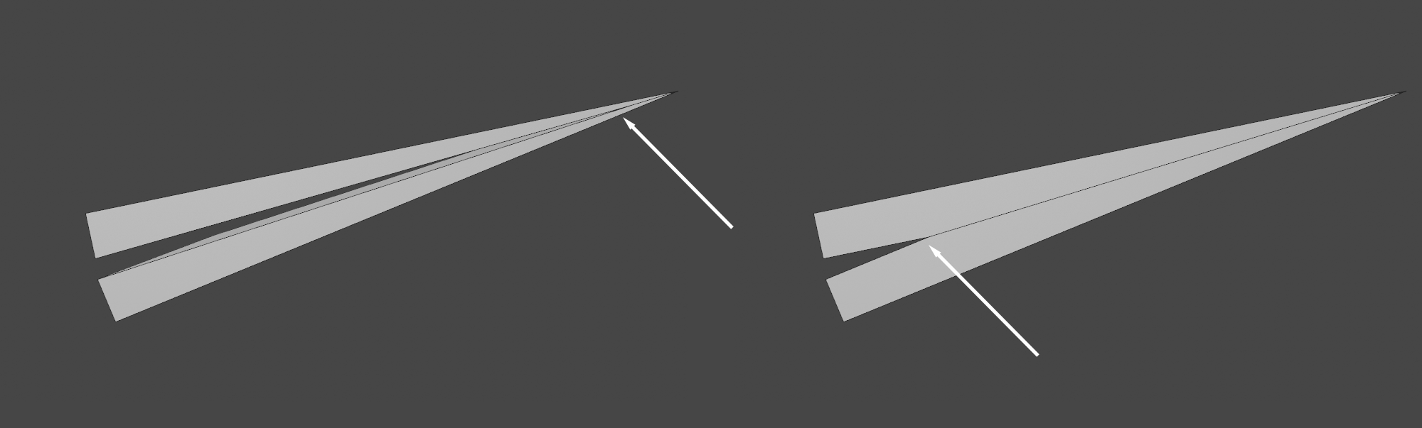 Left small, right large value for Thickness Limit.
Here you can define the directions in which start and end caps surfaces should move depending on the Thickness setting At -100% the duplicated surface will be shifted inwards against the normal, at +100% outwards, at 0% both surfaces will shift equally in opposite directions. Intermediate values work accordingly.
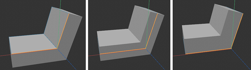 Here, an angled plane is provided with a wall thickness. The outer edges of this plane can be seen as a colored selection and illustrate the position of the initial geometry within the thickened geometry when different position values are used (in this example -100%, 0% and 100%).
If you want to evenly subdivide the polygon strip created at the edges between the start and end deck surfaces into additional strips, the number of subdivisions can be defined here.
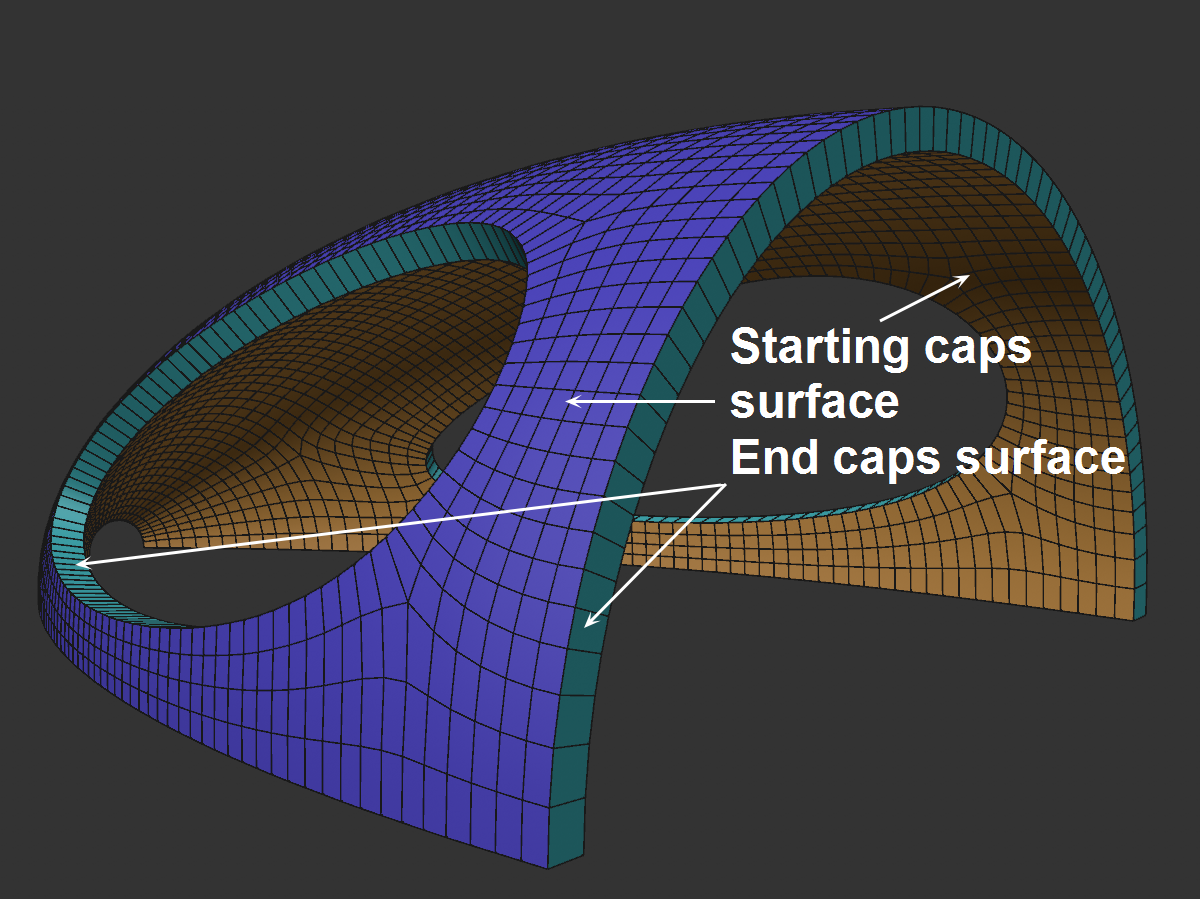
With these three options you define which surfaces should be created. According to the preset, all of them are visible at first.
These and the following settings can only be selected in the Advanced mode. For example, they provide additional methods for producing clean wall thickness geometry - especially at inner corners and bends.
As the wall thickness increases, the points of internal contours converge more and more and fan out again when crossed. This undesirable behavior should be prevented by activating options, in that approaching points are positioned congruently and are even welded into one point when Optimize is activated. However, depending on the geometry and Thickness, this does not always work perfectly.
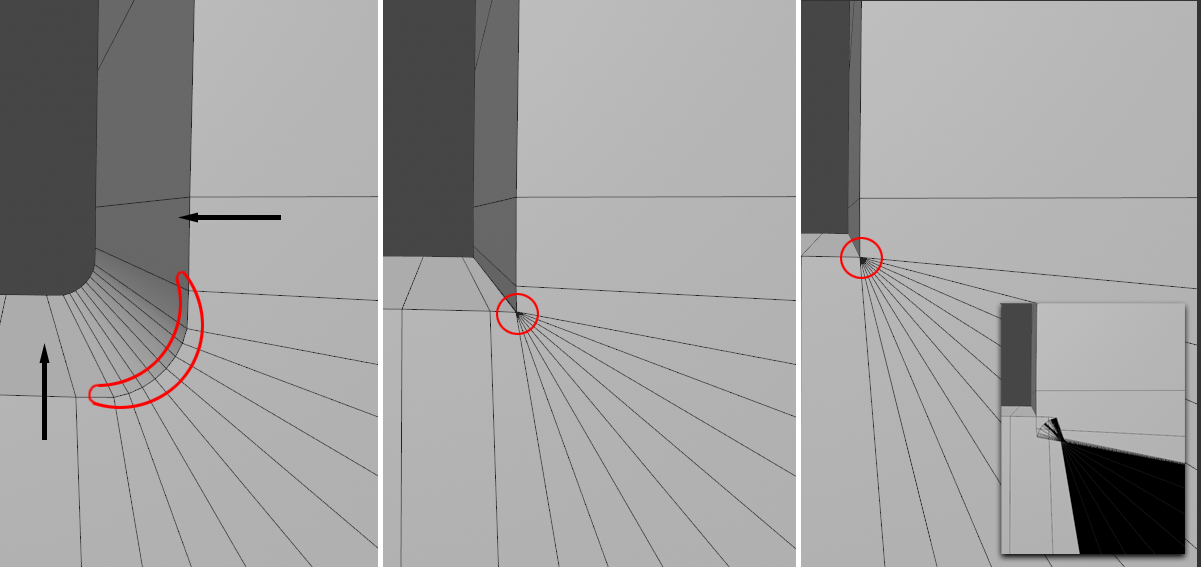 Increasing Thickness values from left to right. The points marked on the left are increasingly converged. Disabled Resolve Intersections.option on the bottom right.
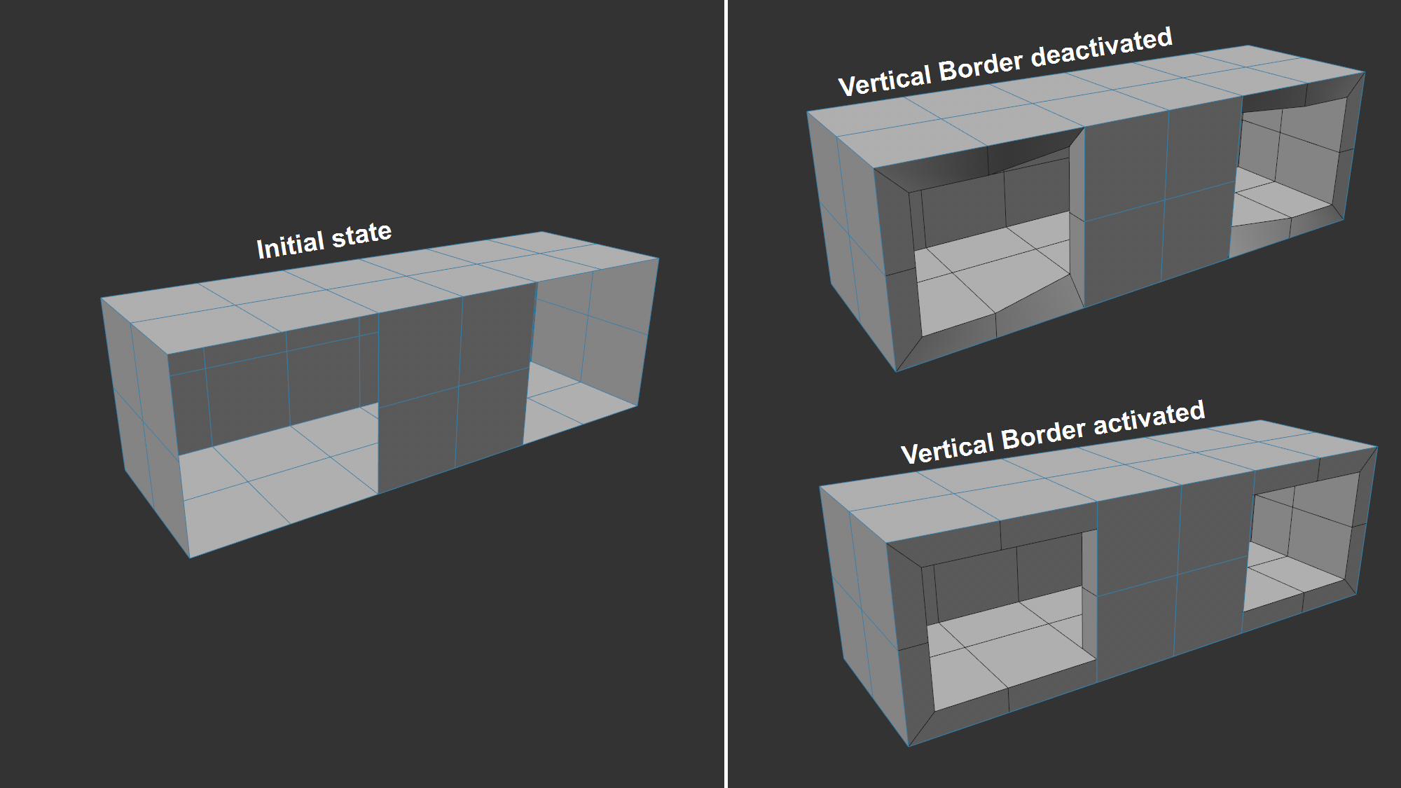
When generating the wall thickness, it can happen in certain constellations (s. image) that the generated edge is twisted to ensure a continuous transition. This is rarely desired and can therefore be prevented by varying the Perpendicular Boundary value. This ensures that the polygons of the newly created border are always perpendicular to the two surfaces creating the thickness.
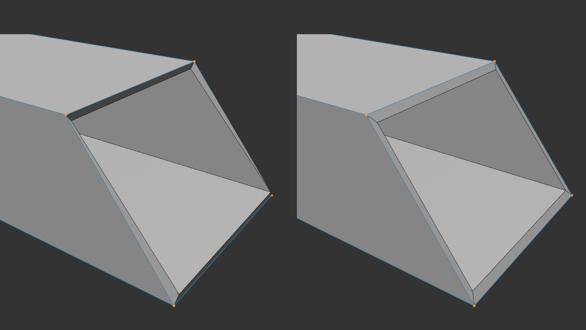
With diagonal "cuts" - as shown on the left - undesirable edge effects can occur. In such cases, the variation of Preserve Corners helps (right). This works best if the cut is on a plane, the edge will do.