Points Modifier
This Node simplifies the manipulation of point positions, Normals, weightings and vertex colors on a geometry. This can be used, for example, to create your own deformation objects or to calculate individual color or weight gradients on a geometry. For this reason, it makes sense to use it within a Node modifier, which then also facilitates the conversion of the point coordinates between the different reference systems of the object to be modified and the modifier in the Object Manager.
Consider the following illustration for clarification. A simple cube was modified with a Points modifier in order to calculate a limited deformation along the X-axis.
This function can only be used in the Object Manager if it is used there within a Node modifier.
General instructions for using asset construction capsules in the Object Manager can be found on this page.
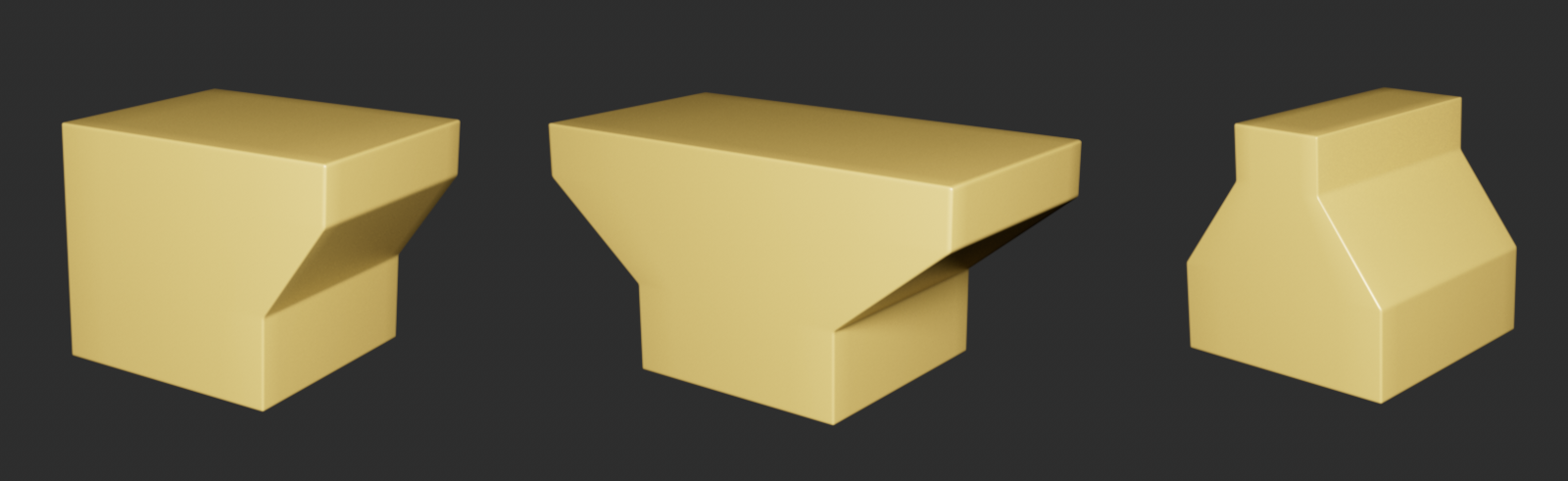 Here, a cube was processed by a Points modifier that performs a specific deformation along an axis direction.
Using the Points modifier as a deformer, or to change existing point positions of a geometry, makes particular sense within a Node modifier (see asset construction groups), as a transformation matrix can also be accessed directly there, which can also be used to convert the point positions relative to the matrix of a capsule in the Object Manager. Let's take a brief look at the above example of a deformation function:
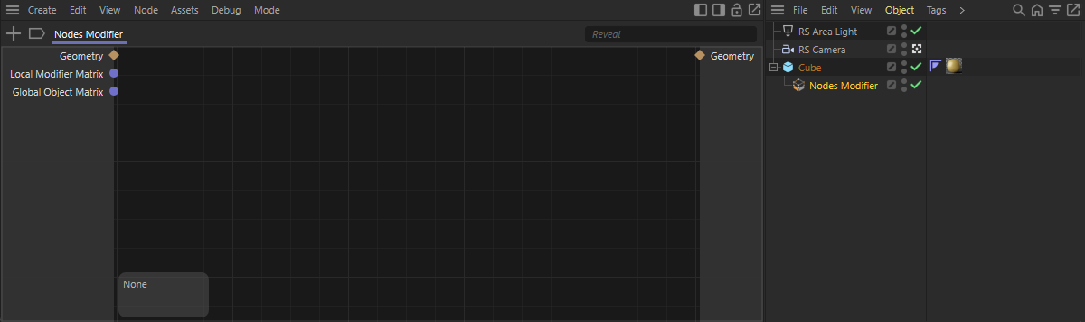 A Node modifier is assigned to a cube in the Object Manager. Double-clicking on its icon opens the Node editor in Capsule mode and displays the initially empty content of the Node modifier.
As can be seen in the figure above, the first step should be to call a Node modifier, which is subordinated to a geometry in the Object Manager. Double-clicking on the modifier icon opens the Node editor and displays the content of the modifier. Ports are available on the left-hand side for accessing the geometry to be processed and the matrices, which also enable the conversion of point positions relative to the position and orientation of the Node modifier.
The following illustration shows how this conversion can be achieved.
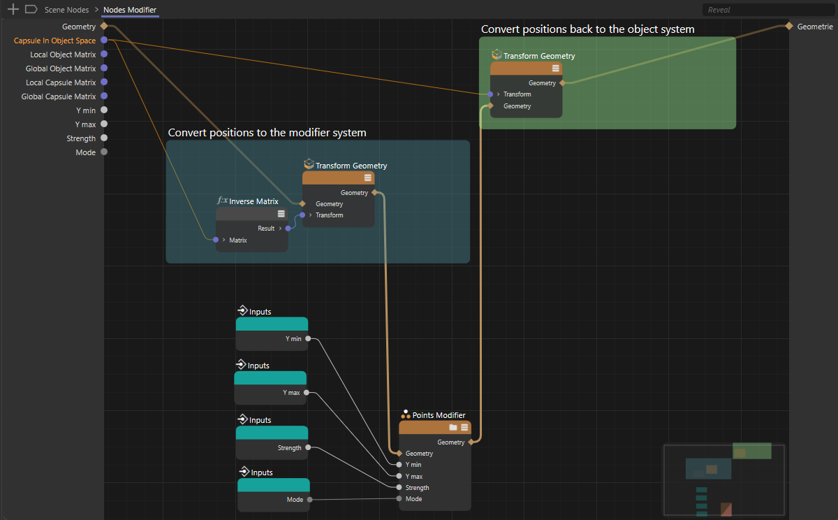 Conversion of the geometry into the local system of the modifier in the Object Manager and back-conversion of the geometry changed by the Points modifier to correspond to the object system of the Object Manager geometry again.
As can be seen in the figure above, the Transform Geometry Node is well suited for converting the geometry into a new reference system as required. If the local modifier matrix is inverted with an Inverse Matrix Node, it can be used to convert the point positions into the reference system of the modifier when transforming at the Transform Geometry Node. The Type setting on the Transform Geometry Node is already correctly preset to points.
After changing the point positions in the Points modifier, a Transform Geometry Node again ensures that the changed geometry is converted into the system of the Object Manager object. For this purpose, the local modifier matrix is used directly for transforming.
The following illustration shows how the actual change of point positions could then take place within the Points modifier. Access to the properties of the geometry is automatically offered there via various ports. Sequential processing is already supported. This means, for example, that you can call up the positions of the selected points directly at the Position input and process them in sequence. It is therefore not necessary to iterate through a field. As can also be seen in the following illustration, simply forward the changed position to the output of the same name at the end of the calculation. The Geometry output of the Points modifier is updated automatically.
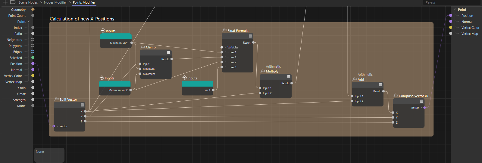 The properties of the geometry introduced are automatically made available as an iteration, such as the point positions or the normals.
By clicking on the following icon, you can load the displayed circuit as a pure Node circuit: