
Meshing of Pyro simulations
The following topics will be covered:
Meshing of animated simulations
The internal structure of the Pyro simulation with its Voxels also allows for other exciting combination possibilities. For example, you can store individual properties, such as the density or the temperature, in RAM at the Pyro Output object if you mark the corresponding options in the Object tab with On. If you now group the Pyro Output object under a Volume Mesher, the Pyro properties stored in RAM will be filled with voxels and converted to polygons. You have even more control over this conversion if you group the Pyro Output object under a Volume Builder and then place it under a Volume Mesher. Thus, at the Volume Builder, you can also use its Voxel Size to set the subdivision density at the polygon mesh. Please note that only the denser gas regions are covered by these Voxels. The finely fanning gas and its density or temperature are therefore not taken into account by default. You can influence this via the Voxel Range Threshold on the Volume Mesher.
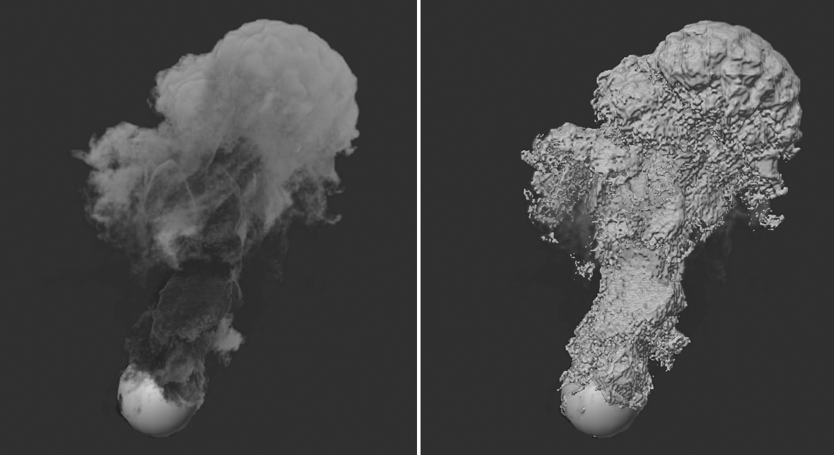 On the left you can see a density simulation for which the storage of density information in RAM has been activated in the Pyro Output object (Density marked with 'On'). On the right, this Pyro Output object has been grouped under a Volume Builder and a Volume Mesher. Polygons are created in the area of the density, which can be covered with materials as usual and can also be rendered without Redshift, if needed.
Applying color information
Density Color information can also be used for meshing. This requires a little sleight of hand.
First, set up your Pyro simulation as usual. To use colors, enable the Color option in the Density settings of the Pyro Emitter tag. In the example below, two spheres were given different colored Pyro Emitter tags and animated in position to make the smoke from both Emitters mix more.
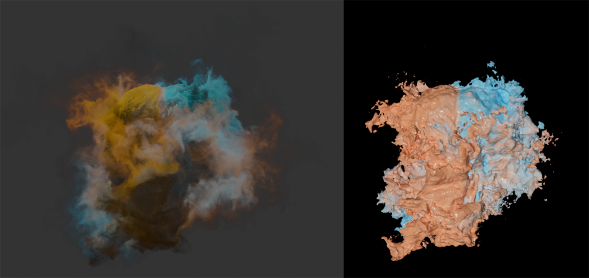 On the left you can see the Pyro simulation with the smoke of two spheres, each sphere producing differently colored smoke. To the right, you can see the result calculated as a mesh, where you can also see the different colors.
In order for us to process the simulated colors separately, we need the colors as RAM cache or .vdb cache files. For meshing to work using a Volume Builder and a Volume Mesher, we also need the density information. We therefore proceed in such a way that we duplicate the already existing Pyro Output object. At the first Pyro Output object we enable only the calculation of Density On Export. On the second Pyro Output object we activate only the Color On Export option. Then we use the Cache functions of these objects and have the cache files calculated there respectively. Make sure to store separate cache sequences for Density and Color, i.e., use different locations and names. One Pyro Output object then reads only the density and the other reads only the simulated colors from the .vdb files.
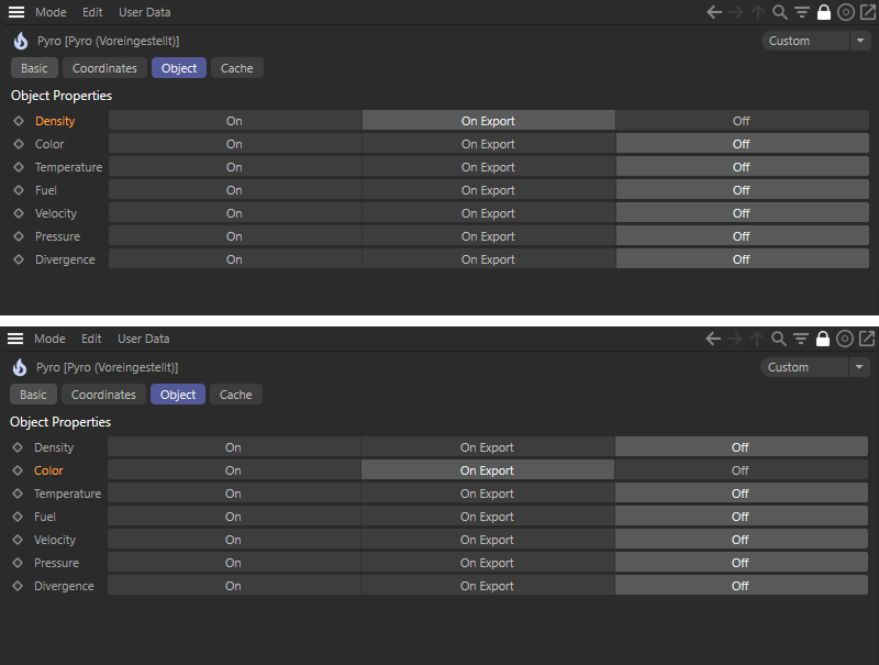 We need a total of two Pyro Output objects. The first one stores only the density simulation as a vdb sequence, the other Pyro Output object creates only a vdb sequence for the simulated colors of the Pyro Emitter tags.
Now create a Volume Builder and group the Pyro Output object there, which reads the Density cache. Use a Volume Mesher over the Volume Builder to have the geometry calculated. If necessary, adjust the Voxel Size on the Volume Builder until you are satisfied with the level of detail of the representation.
Now add a Vertex Color tag to the Volume Mesher. You can find this tag in the Object Manager under Tags/Other Tags. In the Fields section of this tag you can now assign the Pyro Output object that reads the Color cache. This color information is thereby assigned to the individual points of the Volume Mesher.
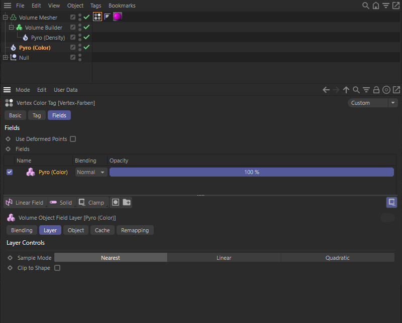 A Vertex Color tag reads the color information of the one Pyro Object and transfers it to the points on the Volume Mesher.
To be able to use the colors of the Vertex Color tag within a Redshift material, we use a Vertex Attribute Node there. In its Attribute Name field, simply drag the Vertex Color tag from the Object Manager into it.
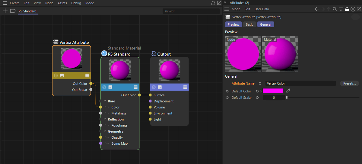 The vertex colors of the tag are read within the Redshift material with a Vertex Attribute Node and can then be used as a base color, for example.
As an alternative to the explained way of storing two separate vdb cache sequences, you can also switch the two Pyro Output objects for the Density and Color properties to On each and thus have two separate caches created in RAM. This also works with the setup described.
Meshing of static simulations
In many cases it may not be necessary to convert an animated simulation to polygons. Meshing of a specific simulation frame is often sufficient. In that case, a .vdb cache file can also be used for a single simulation image. To do this, proceed as follows:
- Run the simulation as usual until the desired state is reached.
- Press the Set Initial State button found in the Pyro Scene settings of the Pyro Output object.
- This creates a new Volume Set object in which the individual properties of the simulation are managed. The Volume Set object provides these properties within a Volume Grids list.
- In the Volume Grids list, select the property you want to convert as a mesh. Often, for example, this is the density, which contains the density of the simulation. Then press the Detach button below the Volume Grids list, which will create a Volume Object in the scene containing a .vdb file for the selected individual component of the simulation.
- This Volume Object can be directly grouped to a Volume Builder like a normal polygon object to create voxels. Since the density can have very fine gradations, the value for Surface Threshold can be used directly at the Volume Builder to define the density above which voxels are generated. The smaller the Surface Threshold is selected, the more likely it is that areas with low density will be occupied by voxels.
- By adjusting the Voxel Size on the Volume Builder, the level of detail can be selected.
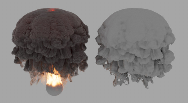 On the left you can see the image of the simulation for which a Volume Set object was created. From this, the density of the simulation was taken out as a Volume Object. If this Volume Object is placed under a Volume Builder and a Volume Mesher, the density can be converted to a polygon object (seen on the right).