

Properties
With these settings, you specify the fineness of the polygon resolution and how the particles of the simulation scene are to be evaluated. These are already the most important settings of the generator.
This is a multiplier for the Radius of the particles. The resulting distance from the particles determines when neighboring particles are still included in a common polygon hull or whether they should be given their own polygon hull separately.
If the Influence Scale is too small, no cohesive liquid is created, but the particles remain visible as individual spheres. If the Influence Scale is too large, particles that are further apart from each other also combine, which can lead to unnaturally large drops, among other things. If you cannot achieve the desired separation between individual drops on the one hand and cohesive liquid areas on the other despite adjusting the Influence Scale setting, this is probably due to the particle density of the simulation being too low overall.
You specify the density of the particles on the one hand via their count and indirectly via the Default Radius of the Scene Settings or via the individual Radius value of the Liquid emitter used. The smaller these radii are, the closer the liquid particles can come to each other within the simulation without causing repulsions. The Target Density setting also plays a role, as a larger density setting allows more particles to be placed in the same volume without causing repulsions between them.
In this context, please also note the Surface Offset described below. This also has an influence on which particles are included in the polygon hull. Finally, the resolution of the polygon hull also plays a role. You adjust this with the following Mode setting, among others. If the resolution of the polygon hull is too coarse, it may not be possible to include all the details or even all the particles.
This can be used to fine-tune which distances between the liquid particles still lead to a coherent polygonal hull. Smaller offset values cause the polygonal hull to contract around each particle, which can lead to a separation of the liquid droplets. Larger values, on the other hand, lead to an expansion of the polygonal hull around the liquid particles. As a rule of thumb, a natural-looking convergence of adjacent liquid droplets is achieved if two to three times the Radius of the liquid particles is used for the Influence Scale and the Surface Offset is set to 0.5. This is at least a good starting point for your own settings.
However, another strategy can also be interesting, in which you first increase the Influence Scale so that all neighbouring drops are connected as desired. In the next step, you reduce the Surface Offset until the desired definition of the shapes is achieved. Negative values for the offset are also possible.
Similar to Pyro Simulations for fire and smoke or when using a Volume generator, voxels are also used to convert a liquid simulation into polygons, i.e. cube-shaped volumes whose calculation you control here. Two modes are available to control the size and thus also the number of voxels.
- Relative: The size of the voxels depends on the Influence Scale of the liquid particles and a separate Steps value. The following relationship applies: Influence Scale * Radius of the liquid particles / teps
The advantage of this mode is therefore that larger liquid particles are automatically subdivided more coarsely than liquid particles with smaller radii with otherwise identical values of the mesher. This can be practical if you want to process different particle groups with liquid particles of different sizes using the same Liquid Mesh. - Absolute: The desired edge length of the voxels can be entered directly as the Voxel Size in this mode. This means that the subdivision density of the calculated liquid is completely independent of the radii or influencing variables of the particles. However, this can also pose a risk for liquids with larger dimensions, as this can lead to very long calculation times and high memory requirements if the Voxel Sizes are not adapted to this.
In general, the following applies to both modes: More voxels result in a more finely divided surface, but also mean more memory and calculation requirements.
This setting is only available in Relative Mode.
Higher Steps values reduce the edge length of the voxels used according to the relationship: Influence Scale * Radius of the liquid particles / Steps. The effect of the voxel size on the level of detail of the liquid polygon hull is also documented in the following Voxel Size value.
This setting is only available in Absolute Mode.
The smaller the voxels, the more precise and detailed the polygon hull of a liquid can be calculated. At the same time, however, the number of polygons and the directly related computing and memory requirements increase significantly. Therefore, always ensure that you only change this value gradually from larger to smaller values in order to avoid the risk of the computer freezing and to find a compromise between the required level of detail and the computing and memory requirements.
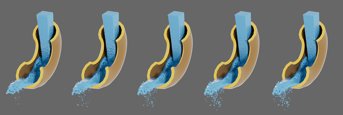 The only difference is in the Voxel Size. From left to right, the values 4 cm, 3 cm, 2 cm, 1 cm and 0.5 cm were used. The difference is particularly clear in the finer waves and the representation of individual drops.
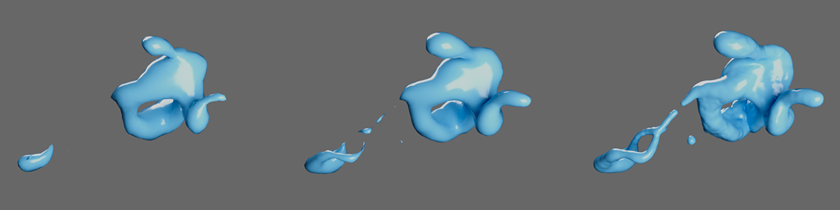 Here, too, increasingly smaller Voxel Sizes are used from left to right. All other settings remain identical. It is clear that the fine structures in particular can no longer be taken into account if the Voxel Sizes are too large.
This can be used to limit the area in which a polygon hull is to be calculated by the liquid particles:
- Static: The area considered for the calculation of the polygon hull can be adjusted manually. Only liquid particles that move within this area are taken into account. The position and size of the cuboid area can be specified individually.
- Dynamic: The area taken into account for the calculation of the polygon hull automatically adapts to the volume in which the simulated liquid particles move. This corresponds to the default setting.
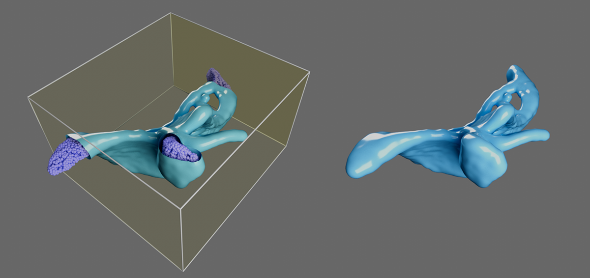 A static bounding box was specified on the left. Particles located outside this cuboid area are no longer included in the calculation of the polygon hull. A dynamic bounding box was used on the right, which automatically takes all particles within the simulation scene into account.
The center of the cuboid area in which the mesh for the liquid particles is to be generated can be specified here for Bounding Box Static.
This can be used to specify the dimensions of the cuboid area in which the mesh for the liquid particles is to be generated for Bounding Box Static. Please note that these values specify the maximum values of the corner points of the bounding box. The vector 100 cm, 100 cm, 50 cm therefore results in a bounding box cuboid that is 200 cm wide and high and 100 cm deep. The dimensions of the bounding box therefore always correspond to twice the specified values.
This option ensures that openings in the generated mesh of the liquid, which can occur at the boundaries of the bounding box when using Bounding Box Static, are automatically closed by polygon surfaces. This ensures that closed liquid volumes are created in every case, which can then also react realistically to transparent and breaking materials, for example.
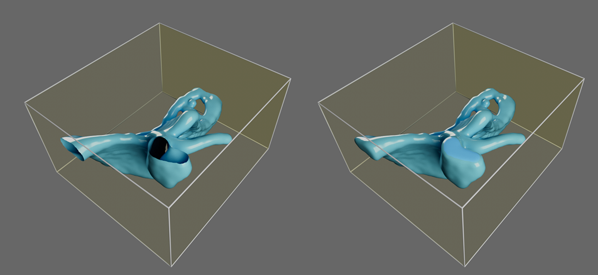 There are particles here that extend beyond the specified static bounding box. The generated mesh therefore ends unfinished at the boundaries of the bounding box (shown on the left). If the option is switched off, corresponding openings remain on the polygon hull, which can be automatically closed by activating the option (shown on the right).
This setting refers to the following Particle Groups list and to which liquid particles of the simulation scene are to be taken into account for the calculation of the polygon envelope:
- Exclude: If Particle Groups have been added to the Particle Groups list via drag & drop, they are excluded from the calculation of the polygon envelope in this mode. As the Particle Groups list is empty by default, all Particle Groups in the simulation scene are always automatically evaluated in this mode.
- Include: This mode makes it possible to calculate polygon hulls only for those Particle Groups that are listed in the Particle Groups list. Particle Groups can be dragged directly from the Object Manager into the object list using the mouse.
Please note that the Liquid Mesh can process all particles that have the Liquid Contribution property, even if this value is only 0% and the liquid particles therefore actually behave like standard particles.
Depending on the selected Mode, the Particle Groups listed here are either ignored for the creation of the polygon hull( Exclude Mode) or only the listed Particle Groups are evaluated (Include Mode).
The list can be filled by simply dragging Particle Groups from the Object Manager into the list field. Alternatively, you can first click on the Pipette symbol to the right of the Particle Groups list and then on the corresponding Particle Group in the Object Manager. After right-clicking on entries in the list, a context menu opens, which can be used to remove individual or all entries from the list, for example. It is also possible to select clicked Particle Groups via this context menu.

These settings round and smooth the surfaces of the polygon hull. The geometry can actually be changed or only the surface tangents are interpolated to ensure a more harmonious shading. Both effects can also be combined.
Activating this option enables the settings for geometry rounding of the generated polygon hull.
Geometry Smooth Iterations[0..2147483647]
This value specifies the number of calculation passes for smoothing the surface. Basically, the more calculation passes are made, the more organically rounded the surface appears, but the longer it takes to complete the updating of the liquid surface for each animation frame. Please also note the following value for the Smooth Strength, as this can be used to limit the effect of smoothing to certain sections of the liquid.
In addition, the subdivision density of the Liquid Mesh to be smoothed, i.e. indirectly the size of the voxels used, is also important for smoothing. A Liquid Mesh that was only roughly formed from a few voxels will change significantly with just a few smoothing iterations, whereas a densely subdivided mesh may require many iterations until the desired effect can be seen.
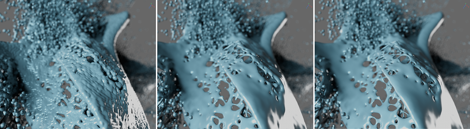 The unsmoothed liquid is shown on the left, while the figures on the right show the effect of 5 and 10 smoothing iterations.
This is used to regulate the influence on the liquid surface for each iteration of smoothing. In general, the initial volume of the entire liquid tends to remain the same at lower values. As the Smooth Strength increases, the surface of the liquid shrinks more during smoothing. This mainly affects the smaller drops of the liquid, which can even disappear completely at higher Smooth Strengths due to the extreme rounding.
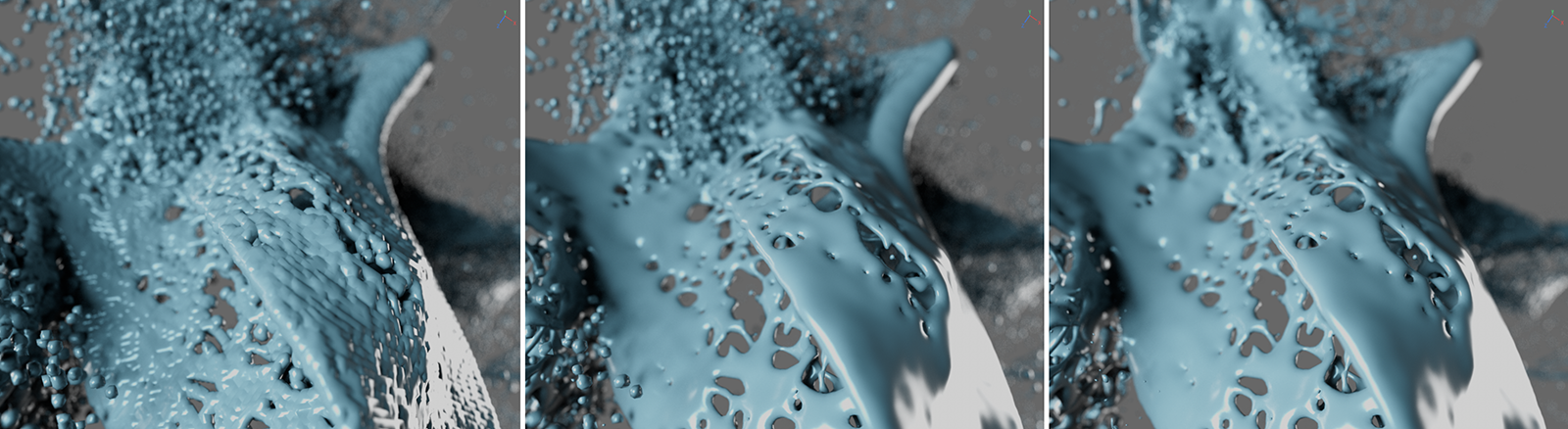 The figures on the right show the effect of 50% and 100% Smooth Strength with 5 Smooth Iterations each. Note in particular the differences in the small drops in the background and bottom left of the individual figures.
Activate this option to smooth the orientations of the surface normals on the liquid. Although this effect does not change the shape of the liquid, it can make it appear more harmonious in the surface shading. The effect is therefore similar to that of the Phong Tag with individually adjusted Phong Angle restriction.
Normal Smooth Iterations[0..2147483647]
This value specifies the number of calculation passes for the optical smoothing of the surface normals. Basically, the more calculation passes are performed, the more harmonious the surface shading appears, but the longer it takes to complete the updating of the liquid surface for each animation frame. In contrast to smoothing the point positions of the liquid, only the surface normals are realigned here. The actual shape and polygon structure of the liquid remains unchanged. There can therefore be no change in the volume of the liquid.
Please note, however, that the realignment of the surface normals also has its limits. Extremely abrupt changes in shape and sharp edges will not disappear completely, even after many iterations. In these cases, combine the optical smoothing of the surface normals with a few real smoothing passes to additionally round off the geometry.
In order to actually be able to use the smoothed normals for rendering, the export of the Normals must also be activated in the Export tab of the Liquid Mesh object.
This activates an additional filtering of the geometry, which can be used to remove interfering protrusions and detached structures consisting of only a few polygons. Depending on the complexity of the liquid geometry, this calculation can be quite time-consuming and is therefore deactivated by default.
You use this numerical value to indirectly specify the number of polygons on a contiguous structure that are still considered artefacts and should be removed if possible. The value 1 corresponds approximately to the number of polygons used on a single sphere with a radius of 5 cm. Accordingly, the default value 2 stands for twice the number of these polygons.
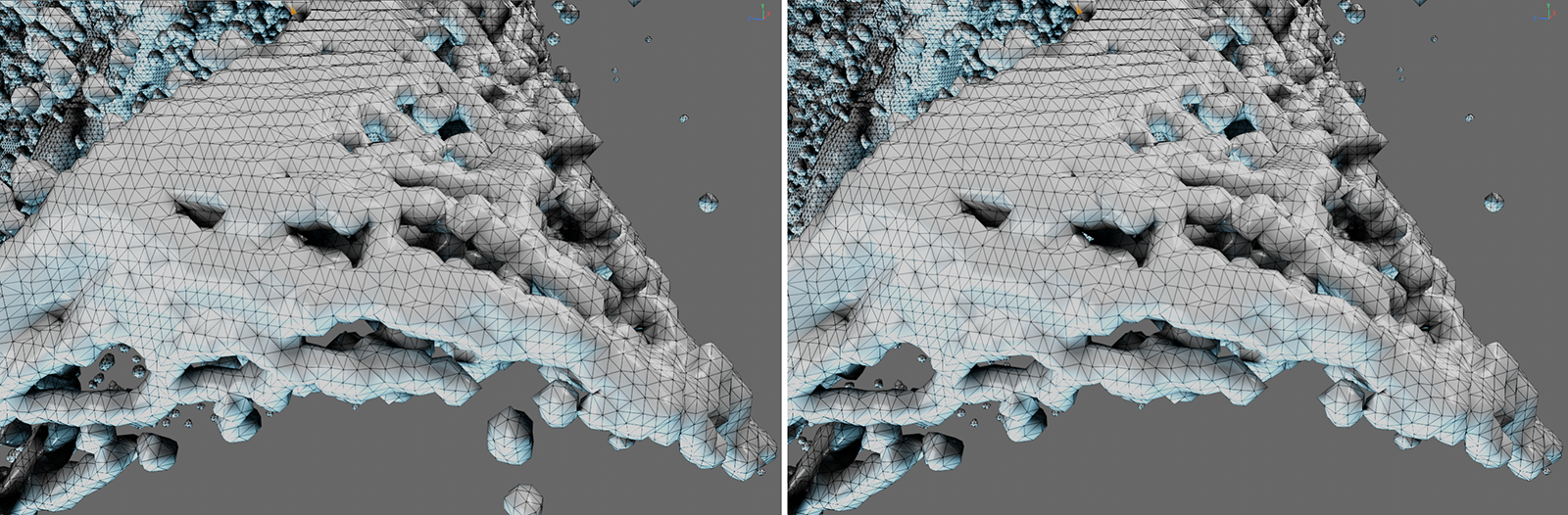 On the left, you can see the original liquid with the Remove Artefact option switched off. On the right, you can see the same liquid with the option activated. Note the changes, especially in the top left corner and also in the bottom quarter of the mesh.
Drops are structures that are formed by a small number of particles floating in space. It can often be visually desirable to delete these structures completely using the Remove Artefact option, for example, or to reduce their size so that they do not distract from the main structure of the liquid. In this case, these functions, which can be used to automatically reduce the size of individual drops, are helpful.
With values below 100%, the individual drops in the geometry can be automatically reduced in size. The following threshold value can be used to specify what is to be recognized as a drop.
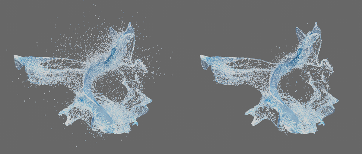 On the left with the value 100%, on the right with the value 0% for the Droplet Scale.
Droplet Threshold[0..2147483647]
This value specifies the number of neighboring particles that should still be considered as a single drop. Structures that contain more particles are no longer affected by the scaling.
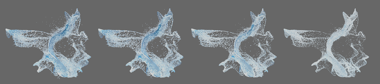 The effect of increasing values for the Droplet Threshold can be seen here from left to right.