
Group
In this section you will find all the settings to control the type of tendril and leaf geometry created. For example, the tendrils themselves can also be output as simple splines or the leaves can be completely excluded from the calculation. There are also parameters here to control the orientation of the leaf geometries and to influence the subdivisions and thicknesses on the tendrils.
Use this menu to select how the tendrils are to be calculated. Polygon objects can be created, which can be directly assigned materials and rendered, or optionally splines, which can then be individually shaped using generators such as the sweep.
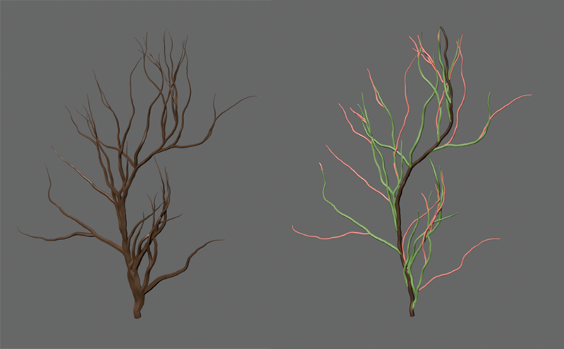 Geometry was created on the left, individual splines for the main part (trunk, colored brown here) and the main and secondary branches(branch 1, colored green here and branch 2, colored reddish here) on the right. The splines in the right half of the image were rendered with the help of Redshift object tags. Generators therefore do not necessarily have to be used for rendering the spline tendrils.
The following options are available:
- Geometry: All tendrils are represented by polygon objects. Their subdivisions can be influenced, for example, via Vine Sides and the Subdivision values further down on this settings page. In this mode, the tendrils can be directly assigned materials and rendered.
- All Splines: All tendrils are represented by spline segments on a single spline.
- Trunk Spline Only: Only the main part of the ivy is calculated and output as a spline (see brown colored section in the right part of the figure above).
- Branches Splines Only: Only the branches branching off from the main part of the tendril are calculated and output as splines. These sections are colored green and reddish in the right part of the above illustration.
- Branch 1 Splines: Only the branches branching off directly from the main part of the tendril are calculated and output as splines. These sections are colored green in the right half of the figure above.
- Branch 2 Splnes: Only the secondary branches are calculated and output as splines. These sections can be seen in reddish color in the right half of the figure above.

In these settings groups, you can define the inclination and density of the surfaces that can be covered with sheet materials, for example. If you only need the tendrils, the calculation of the leaf areas can also be switched off completely here.
Leaves
Use this option to switch the calculation of the leaves on the plant on or off. Only when switched on do you have access to most of the following settings, which can be used to adjust the blade inclination and density of the blades along the tendril.
This percentage value can be used to influence the random distribution of the leaf geometries along the tendril. If the values are small, fewer leaves are produced. The placement of the leaves is always random and therefore depends on the Seed value from the IVY settings page.
The distances between the positions along the tendrils at which leaves can appear are controlled via the separate value for Every nth Segment.
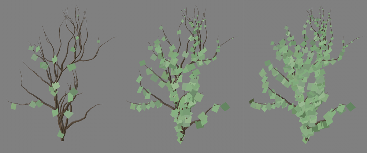 A density of 10% was used on the left, 50% in the middle and 100% on the right.
Max Steps[-2147483648..2147483647]
Here you can define the intervals at which leaves can occur on the tendrils. The smaller the value, the narrower the leaves can be created. How many of these positions that are then actually fitted with leaf geometries depends on the value for Leaf Density.
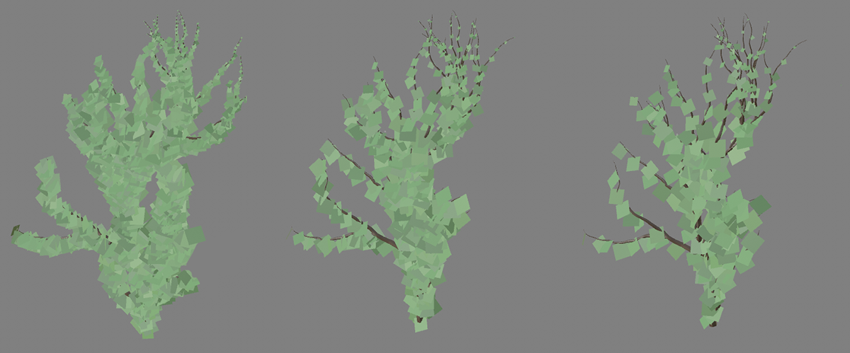 Every nth Segment 1 was used on the left, 3 in the middle and 5 on the right, each with a Leaf Density of 100%.
Here you define the normal size for the leaf polygons. The resulting sizes can also be varied randomly using the value for Leaf Size Variation and can also be designed to taper off at the ends of the tendrils using Leaf Size from End.
Here you can use a maximum percentage deviation from the leaf size defined with Leaf Scale.
On real plants, the youngest and therefore smallest leaves are at the ends of the branches and tendrils. This effect can be simulated with this parameter. You use the order of magnitude of the value to define the number of sheets to be scaled to zero size.
Clinging Leaves
The settings in this section only apply to the leaves that lie within the area of influence of the assigned geometry along which the tendrils grow.
Only if this option is enabled can the orientation of the blades be controlled relative to the assigned geometry, provided they are within the area of influence of this geometry (see Surface Force and Stick Distance Max).
This defines the angle between the geometry along which the ivy grows and the leaves in the area of influence of this geometry. The following video shows this effect. At a greater distance in front of the wall, you will recognize some leaves that do not change their inclination because they are no longer within the range of influence of the wall geometry.
This lets you twist the leaf surfaces around the attachment points on the tendrils. However, as already discussed in Tug Upward, this only affects the leaves that are in the area of influence of the assigned geometry along which the ivy grows. Leaves at a greater distance from this geometry remain unchanged in their orientation.
This setting only affects the leaves that lie within the area of influence of the assigned geometry and grow under overhangs and on the underside of the object. In these cases, increasing the value ensures that the blades are no longer aligned parallel to the surface, but are displayed hanging downwards due to simulated gravity. The following video gives an example. Note the change in the leaves below the upper bar.
You can use this to define the maximum random variation of the rotation angle of the blades. However, this variation only applies to the sheets that are in the area of influence of an assigned geometry (see Surface Object link).
Dangle Leaves
These settings only affect the leaves that grow on free-running tendrils, i.e., that are outside the area of influence of the assigned geometry.
Similar to Cling Gravity, this can be used to simulate a gravitational force that causes the leaves to hang downwards. Here, however, this only applies to the leaves that grow on freely hanging tendrils.
You can use this to define the maximum random variation of the rotation angle of the blades. However, this variation only applies to the leaves that are located on sections of the tendril that hang freely downwards.
Use these settings to set the thickness of the tendrils and their subdivisions.
These values define the start radius of the main branch (Thickness Max) and the end radii at the tips of the branches (Thickness Min). The transitions between these radii are calculated automatically.
Imagine the calculation of the tendril geometry as when using a Sweep object. Splines are often covered with a circular profile to create tubular or tendril-like structures. The radii for the circular cross-sections of the tendrils are defined as Thickness Max and Thickness Min. The detail and accuracy of the geometry is now defined using the following settings.
Here you can define the subdivisions along the circular profile for the tendrils. The larger this value is, the more rounded the tendrils appear in their cross-section and the more polygons are created for the tendrils. However, smaller values between 6 and 8 are often sufficient, as the Phong shading can already simulate a perfectly rounded surface. Only for extreme close-ups can even higher values possibly make sense.
Subdivision Length[0..2147483647]
The geometry of the tendrils is subdivided at regular intervals. The smaller the value, the smaller the distances between the subdivisions. The following illustration shows an example with settings 1 (left) and 10 (right). If you want to use the subdivisions more specifically only where the tendrils change direction, you can also use Subdivision Angle instead.
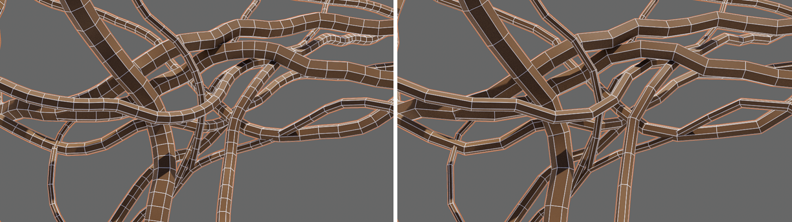 On the left a Subdivision Length of 1, on the right 10 was used. The course of the tendrils does not play a role in this type of subdivision.
The geometry of the tendrils is subdivided according to their course. The greater the change in direction, the narrower the subdivisions in this area. The smaller the angle set, the finer and more often curvatures are divided. Straight sections of the tendrils are therefore not affected. These sections can be further subdivided using Subdivision Length if required. The following figure shows an example with the subdivision angle settings 1° (left) and 10° (right).
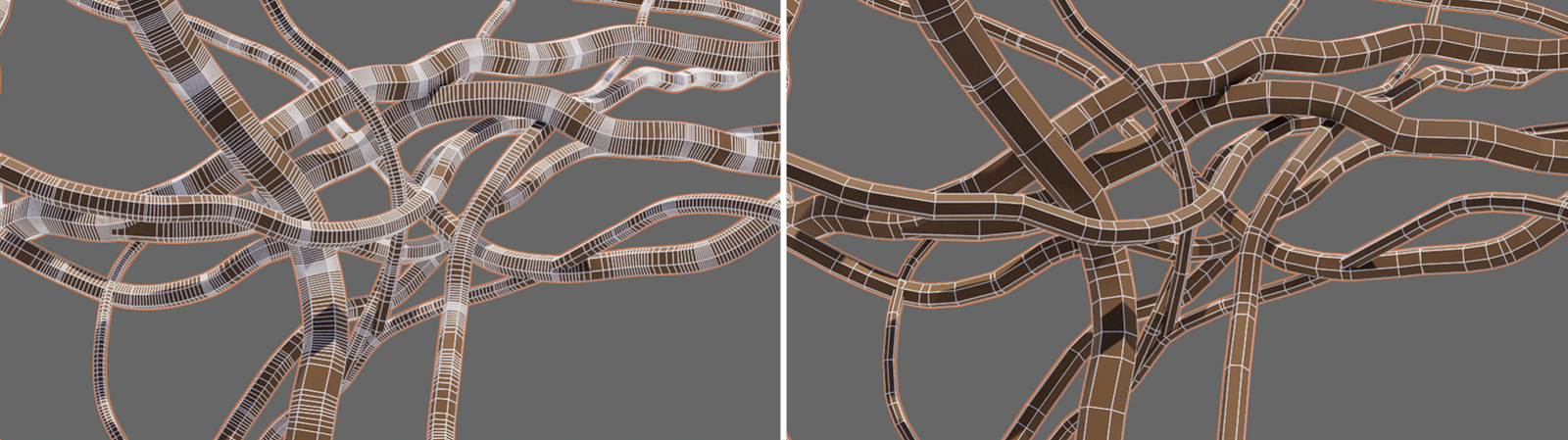 On the left a Subdivision Angle of 1°, on the right 10° was used. It can be clearly seen that the subdivisions are concentrated on the immediate areas with changes in direction.