
Filter
The settings in this group can be used to activate or hide different elements in the UV Editor. Again many of these options should already be familiar from similar options offered in the menu of the viewports.
Enabling UV Grid displays vertical and horizontal lines that divide the width and height of the UV tiles into equal sections. The number of these divisions can be set independently for the horizontal direction using Subdivision U and for the vertical direction using Subdivision V. The default setting of 10 therefore divides each UV tile into squares measuring 0.1 units (10 * 0.1 = 1.0).
If Show Sub-Grid is also enabled, additional lines become visible as you zoom into the UV tile. The effect is therefore identical to the dynamic Grid Spacing in the viewports, except that here UV units—rather than distance units—are being subdivided.
Regardless of the settings for Subdivisions U and Subdivisions V, the currently visible Grid Spacing is also displayed as a HUD element in the lower-right corner of the UV Editor. To calculate this value, the system always assumes an even division into 10 sections between the outer boundaries of a UV tile, or—when zooming in—between these divisions as well.
The visibility of these grid lines, combined with the displayed Grid Spacing value, is particularly helpful when working on UV elements in the zoomed-in UV Editor, as it helps you maintain a sense of scale.
Some information is also displayed directly within the UV Editor, such as the current Grid Spacing value. Additional info can be added to the HUD by activating the options found in the HUD tab of this Configure dialog. If you prefer not to have text overlays within the UV Editor, turn this option off.
UV tiles are defined by specified coordinates. The standard tile always lies between the values 0.0 and 1.1 (0 to 1 horizontally, i.e., in the U direction, and 0 to 1 vertically, i.e., in the V direction). However, by using UDIM, additional tiles that lie outside this standard tile can also be used. The UV tile adjacent below, for example, contains the UV values 0 to 1 in the U direction and -1 to 0 in the V direction. To make it easier to identify the different UV tiles and their UV values, this option allows you to display the corresponding UV coordinates at the corner points of the tiles.
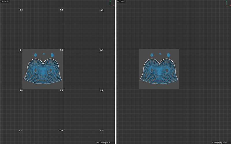 The UV Editor grid with and without displayed UV Corner Units.
Using a specific naming convention for the textures loaded into materials (see the explanation on using UDIMs here) allows you to map textures to specific UV tiles. Within the UV Editor, using UDIMs means that even a texture marked as tiled (see the Tiled Texture option) is only displayed within the default UV tile. Only when UDIM Tiles are disabled can the tiling of the loaded texture be transferred to adjacent UV tiles. However, this option has no effect on the actual rendering of assigned materials.
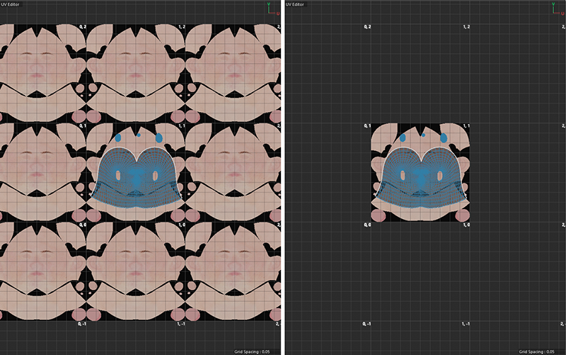 On the left is a view of a tiled texture with the UDIM Tiles option turned off; on the right, the option is turned on.
If UDIM Tiles is disabled, a loaded texture can also be displayed a tiled, starting from the 0..1 default tile. The separate Tile U and Tile V options allow you to control the texture's repetition independently in the U and V directions.
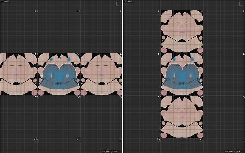 On the left is the effect of Tile U, and on the right is the effect of Tile V.
Whenever UV elements are selected, an additional axis system is displayed for them. This Modeling Axis can be used, for example, in conjunction with the Move tool to offset the elements horizontally or vertically. In addition, these transformation tools also offer settings for this Modeling Axis, for example, to move it within the selection. This then allows, for example, the rotation of selected elements around a rotation point that may also lie outside the selection. The Modeling Axis is only displayed in the UV Editor when Axis is active.
Some tools provide handles for interactive use. This option can also be used to hide these visual handles.
Internally, N-gons are also formed from triangles and quadrilaterals. When this option is enabled, the edges of these internal polygons are also visible within the N-gons.
Elements that can be selected (points, edges, polygons) will be highlighted when the cursor is placed over them.
UV Polygon Indexes corresponds to the Polygon Indexes option in the menu of the standard viewports and can display the index IDs of the selected polygons directly in the editor. This can be helpful in conjunction with Scene Nodes, which also allow you to select polygons based on this number, for example. Similarly, all points in the geometry are identified by unique numbers (also see Point Indexes option for the viewports), which can also be displayed using the UV Point Indexes option.
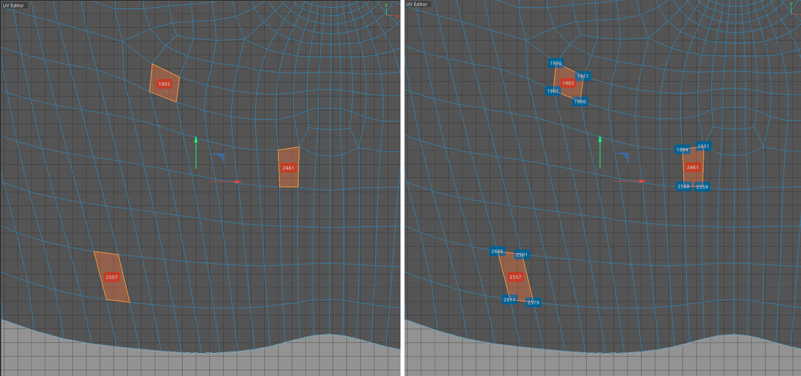 Each polygon is identified internally by a unique ID, which can also be viewed directly in the UV Editor for selected polygons (see left side). Similarly, all points in the geometry are identified by unique numbers, which can also be displayed (see the right side of the figure).
This option toggles the display of polygon indexes between the indexes of the faces contained in the n-gon and the ID of the entire n-gon face. UV Polygon Indexes has to be active at the same time.
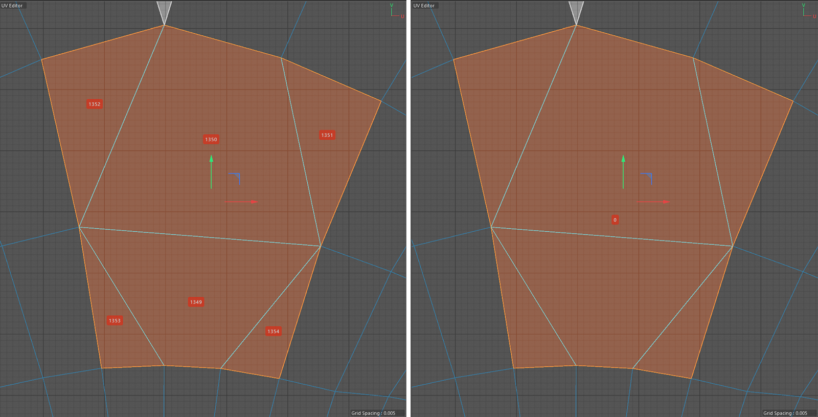 On the left are the IDs of the individual polygons that make up an N-gon; on the right is the ID of the entire N-gon. The option for N-gon Lines has been enabled here for clarity.
Ignore hidden Polygon Selection
Using >Hide Selected a current selection of polygons can be hidden from the viewport display. Activating Ignore hidden Polygon Selection will still show these polygons in the UV Editor. However, it is no longer possible to select these polygons individually as long as they remain hidden.