

Draw
Here you will find all options to control the display of the particles in the viewport group. This has no influence on the display of the particles during rendering. For this you will find separate options, e.g. on the Redshift Object Tag, which is often used together with Particle Groups. The different displays can already provide helpful information on the speed, flight direction, orientation and radius size of the particles.
Here you select how the particles are to be displayed in the views. Various complex shapes are available, all of which can be individually adjusted using the separate Draw Size value in the display size:
- Points: The particles will be displayed as points or slices aligned with the camera.
- Ticks: The particles will be displayed as four-point stars.
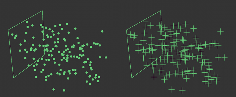 The particles are displayed as Points on the left and as Ticks on the right. The size of the display can be adjusted individually.
- Arrows: Arrow-shaped representations are used, starting at their broad end at the position of the particles. The arrowheads always point in the Z-direction of the particle systems, and the length of the arrows represents the absolute velocity of each particle.
- Lines: This mode is similar to the Arrows display in terms of information content. However, instead of arrows, simple lines are used here, which have a darker and a lighter section. The darker end of the line starts at the position of the particles and points with its lighter end in the Z direction of the particle systems. Here too, the respective line length represents the absolute speed of the particles. Particles with short lines are therefore slower than particles with longer lines.
- Handles: Axis systems are drawn whose origin lies at the position of a particle. The axis directions reflect the orientation of the respective particle axis system.
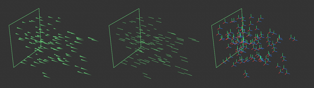 On the left are the Arrows, in the middle are the Lines and on the right are the Handles of the particles on the Particle Group.
Particles have a Radius property that can be used, for example, to control the size of the particle display during rendering. This property can also be displayed as a circle by activating this option. This circular display always corresponds exactly to the Radius property of the particle and can therefore not be adjusted individually by using the Draw Size setting.
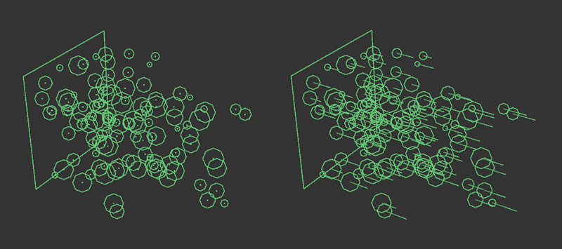 On the left is the point representation with simultaneous radius drawing, on the right is a combination of the line representation with radii.
This value can be used to set the display size of the particles individually. Only the optional Draw Radius is not affected by this, as it always shows the exact Radius property of the particles as a circle.
By default, the displayed color of the particles is defined directly by the emitter of the particles or by special modifiers, such as the Color Mapper Modifier. However, you can also use this setting to override this color evaluation, e.g. to make the group change of particles clearer by using a different color in the views. The following options are available:
- None: The actual color of the particles is also used for their display in the views. As a rule, this is also the color with which the particles are rendered. The color of the particles is determined directly when they are created by the emitter and can then be changed using modifiers.
- Constant: In this setting, the inherent color of the particles will be suppressed for the display and replaced by the Overwrite Color (Display).
- Direction: The flight directions of the particles are broken down into X, Y and Z components, which then become the red, green and blue values of their new display colors. Blue-colored particles therefore mainly fly parallel to the Z axis, green-colored particles travel in a vertical direction and red-colored particles fly parallel to the X axis. Mixed colors indicate the corresponding mixed directions.
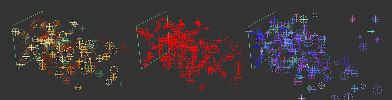 On the left, the original particle colors, which are displayed in the None setting. In the middle, the Constant mode and a red color were selected. This gives the originally randomly colored particles a uniform display color. On the right, the special Direction mode can be seen, in which the particles are colored according to their direction of movement. Mainly bluish colors here indicate a main movement along the Z direction.
You can configure your own color for the Constant Override Mode (Display) here. Click on the color field to open a separate settings dialog with the typical color sliders. You can also click on the small arrow to the left of the color field to expand the color sliders and specify exact RGB or HSV color values, for example.