
Tessellation
Some CAD formats can save meshes in a file. Enable this option if these should be loaded as a polygon mesh in Cinema 4D. No separate tessellation (conversion of NURBS to polygons) will then take place. If this option is enabled and no mesh is found, a query will be made if tessellation should take place using the current settings.
A CAD file contains tiny objects as well as a huge structure, which are all essential for the project. In a visualization, tiny objects like nuts and bolts don’t play a major role and don’t need to be imported with the same resolution as the larger objects.
Scale-Based Tessellation can be used to arrange objects in 3 scale categories for separate tessellation (described above):
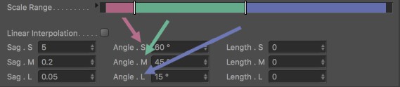
The bounding box sizes (more precisely: the largest diagonal) are ascertained for the objects to be imported and grouped relative to the largest bounding box. Percent values will be produced that are shown in color in the image above with increasing values from 0% to 100% from left to right. The sliders can be moved as desired. The selected slider’s value will be displayed if you click on the small arrow to the right of Scale Range.
This option belongs to the Scale-Based Tessellation settings. If enabled, it will disable the middle range and interpolation will only take place between minimum (S) and maximum (L).
Defines the Distance (see below) for the 3 large regions.
Defines the Angle (see below) for the 3 large regions.
Defines the Length (see below) for the 3 large regions.
When importing a NURBS surface, these three-sided polygons have to be reproduced. This process is called tessellation.
The Detailing settings can be used to define how precisely the polygon mesh that is generated should follow the NURBS surfaces.
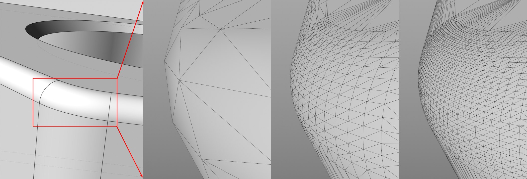 The NURBS surface on the left after Tessellation with Detailing set to Low, Middle and High, respectively.
Detailing offers the following options:
- Original: the tessellation values saved in the CAD file will be used.
- Custom: will automatically be used if you manually enter values.
- High, Medium, Low: applies the respective quality level to the Max Sag and Max Angle settings (click on the small arrow to display these settings).
Note that the tessellation process takes into account all 3 defined maximum values for Max Length (mm), Max Angle and Max Sag (mm). The maximum resolution will be calculated within these limits. Generally speaking, the smaller the values, the higher the resolution. If 0 is defined, the respective criteria will be ignored.
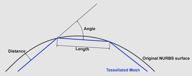 Depending on the settings defined, the polygon mesh will follow the curvature more or less precisely.
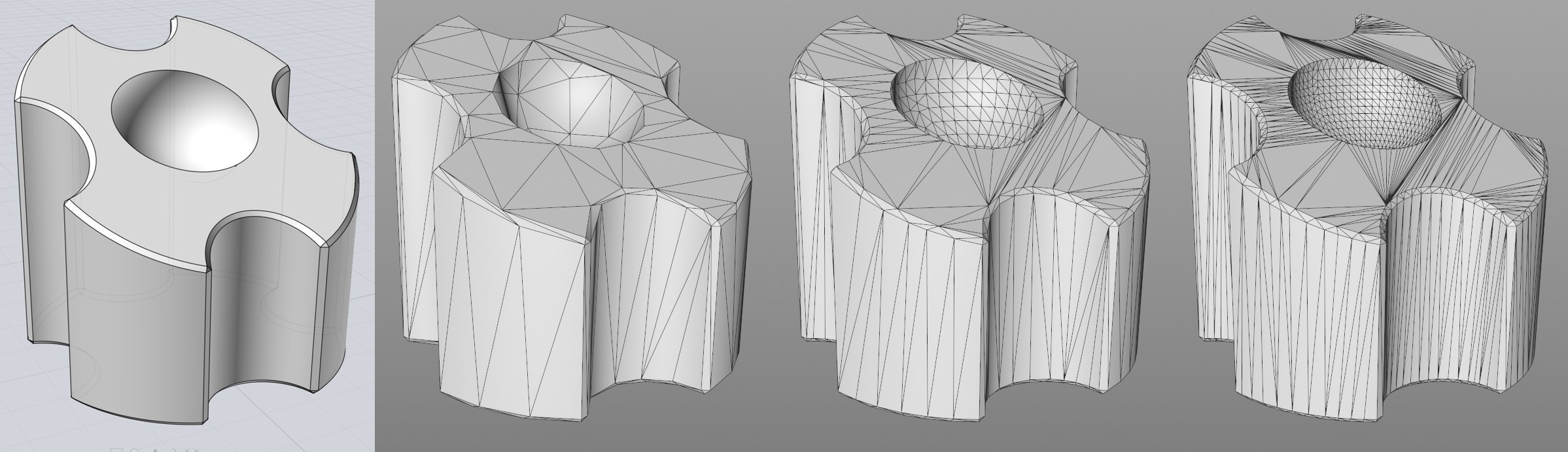 The original NURBS on the left; declining Max Sag (mm) values from left to right (other criteria disabled).
This value defines the maximum distance the polygon surface can have from the NURBS curve. Define smaller values for correspondingly higher polygon mesh resolutions.
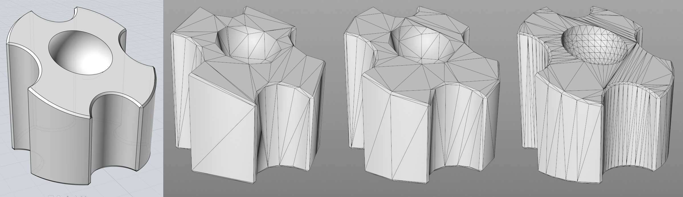 The original NURBS on the left; declining Max Angle values from left to right (other criteria disabled).
Max Angle defines the maximum angle between adjacent polygon surfaces that cannot by exceeded (see image for Max Sag (mm).
Max Length (mm)[0.00..999999.00]
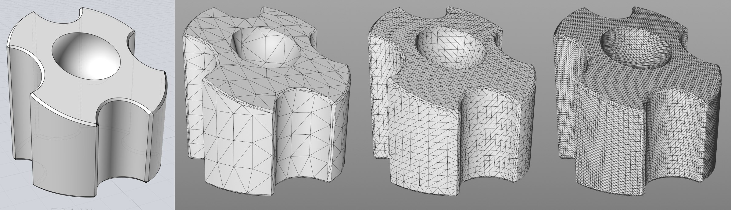 Left: Original NURBS; from left to right sinking values for Length Max (mm) (other criteria disabled).
Length Max. (mm) defines a triangle’s maximum side length. Lower values make it possible to avoid the often problematic, very long triangles. But be careful: values that are too low will generate an unnecessarily high number of triangles.