

Electric
Here you will find the main settings of the node to control the intensity and type of deformation. You can also automate deformation animations and activate bundles of deformed spline curves.
Activate this option if you want to adjust the point density of the inserted spline before processing. The Step width value can then be used to control the density of the uniform subdivision along the inserted spline.
If Resample has been activated, you can specify the distance between the points along the spline here. Smaller values therefore lead to more points. The deformation can then be carried out in even greater detail. At the same time, however, the calculation becomes more complex, especially when working with many clones.
This is the maximum distance that shifted points should be moved rom the original spline curve.
This 3D vector can be used to adjust the displacement of the points individually along the X, Y and Z directions. Values above 100% mean that point displacements can also occur beyond the value set for Displacement. Values below 100%, on the other hand, reduce the displacement of the points along the corresponding world axis direction.
This corresponds to the start value for all functions based on a random or noise calculation. A change to this value can therefore be used to calculate a new flash variant without having to change other parameters.
This can be used to specify the amount of time that must elapse for a new version of the flash to be calculated. To do this, the Override Time option must also be activated. If you then use Time 10 B, for example, the flash curve only jumps to a new shape every 10 animation frames when the animation is played and remains static in between.
Here you can choose from the common noise types with which the deformation on the spline is to be calculated. Here you will find an overview page of all available noise structures.
This value scales the selected noise pattern before evaluation. Small values enlarge the pattern, which means that the deformations of the spline are less abrupt and spread over a greater length. Larger values reduce the noise pattern, which often leads to a greater variation even in short spline sections.
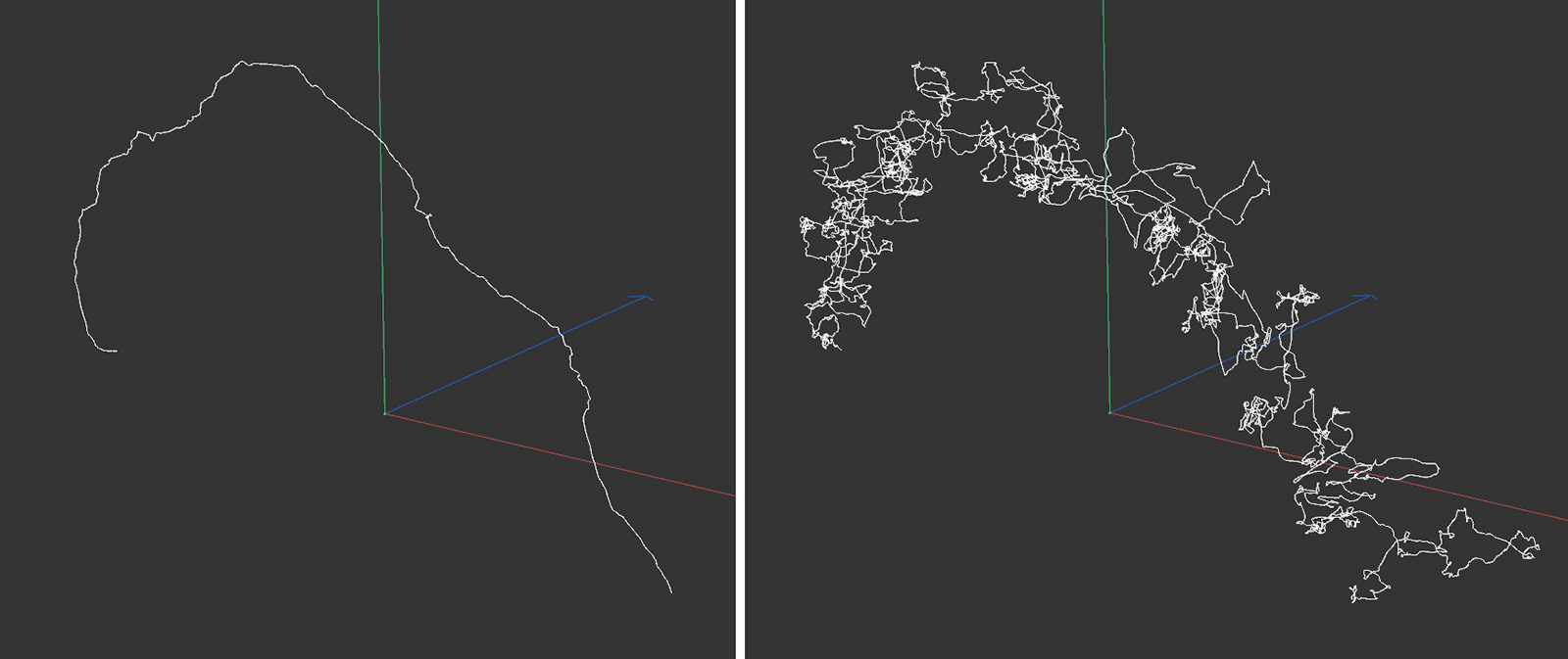 A small value was used on the left and a large value on the right for scaling the noise structure. All other settings remained identical.
This can be used to set the detail density of the selected noise pattern. Higher values generally lead to more details in the selected pattern. In order for these to be visible, the number of points used on the spline may have to be increased via the Step value.
This option can be used to control the frequency with which the flashes are recalculated. When switched off, the flashes are automatically recalculated for each animation frame. When switched on, the Time value is used and can specify a period of time that each flash should remain static until recalculation takes place. With a Time value of 5 B, a new flash structure is therefore only created every five animation frames. In combination with Time 0 B, the flash remains permanently static and no longer changes automatically during the course of the entire animation (unless the Time value is animated manually to vary the noise pattern).
This value is available if Override Time has been activated and enables the manual animation of the noise change. A value change must therefore be animated here, e.g. via keyframes, in order to trigger an animation of the noise pattern.
This is a multiplier for the time in the scene. Values below 100% can be used to slow down the changes in the flashes and calculate them as if in slow motion. Values above 100% accelerate the changes in the shape of the generated flash curves.
If the shape change of the generated flashes is to be repeated in a certain time rhythm, you can enter the length of time after which the deformations are to be repeated here. A value of 0 switches off the repetition and there is no repetition in the deformation.
This can be used to move the deformation along the spline manually, e.g. to move a prominent structure to the desired position on a static flash(Override Time activated with Time = 0 F).
Here you specify the offset of the deformation structure on the spline that is added within each second of an animation. In contrast to Movement, this offset leads to an automatic animation of the noise displacement on the spline, while Movement only causes a static offset. Note that if you use Override Time, the Movement Rate offset can no longer be taken into account synchronously with the project time. In this case, it is better to use an animated Movement value.
This can be used to shift the position along the output curve to which the selected noise propagates relative to. Changing this value therefore has the effect of shifting the noise deformation on the resulting splines.
Smooth Iterations[0..2147483647]
This value corresponds to the number of iterations used to smooth the noise deformation. Higher values lead to greater smoothing and a reduction in sharp changes in the shape of the spline.
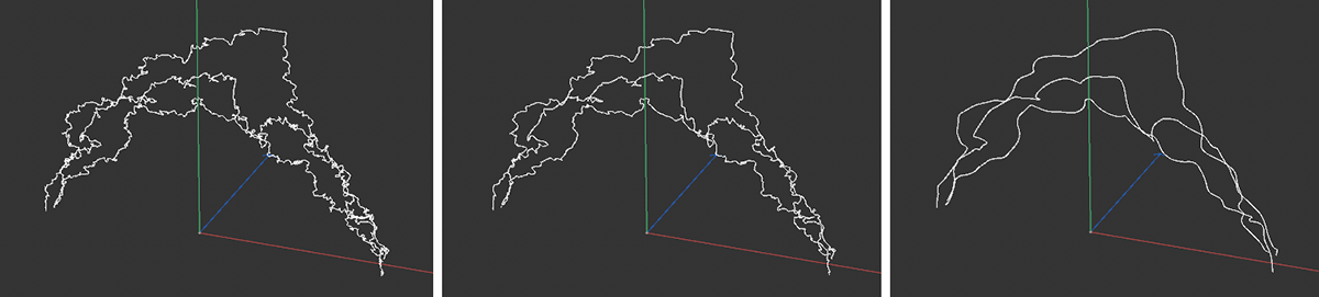 The image sequence shows the effect of increasing smoothing values from left to right.
The desired number of result splines can be set here. Increasing this value then creates a bundle of flashes. Each flash curve automatically receives a new Seed value and therefore looks different. The maximum distance of each additional flash spline from the original spline curve corresponds to the Displacement value. The start and end areas of all flashes can be influenced via the Start and End values.
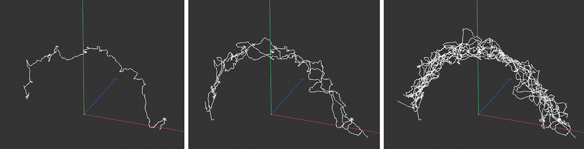 The image sequence shows increasing Clone Count values from left to right.
With this option the noise structure can be varied per cloned curve.
Increasing these values reduces the distance of the generated flashes from the output spline at its beginning and end. If several flash clones are used, this leads to a bundling in these areas. The range of influence of this effect can be increased via the Blend value. With a small Blend value, only the immediate ends of the flashes are influenced. With higher Blend values, the original flash deformation is only retained in the middle of the flashes.
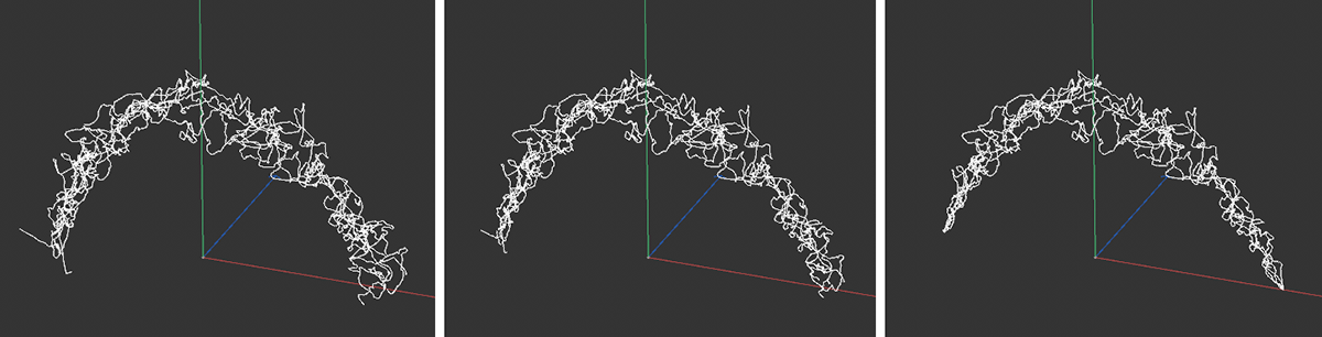 The image sequence shows increasing values for Start and End from left to right. Only the immediate start and end area of each flash is affected.
As the value increases, the range that is influenced by the Start and End values increases.
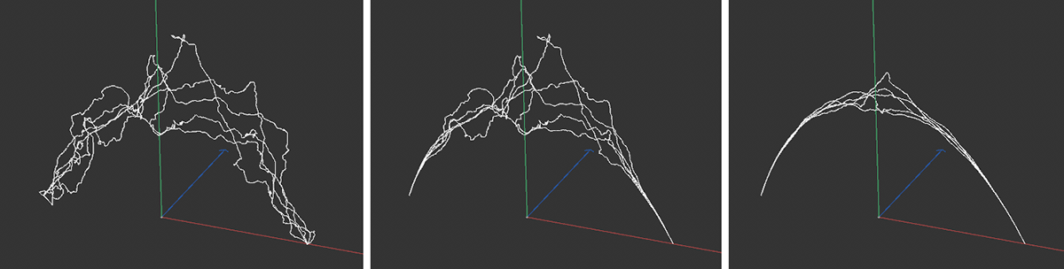 The image sequence shows from left to right the Blend values 0%, 50 and 100%, where 100% was used for Start and End respectively.
Increasing values can be used to move the reference system for the constrictions from the starting point towards the end point. The following figure gives an example of this.
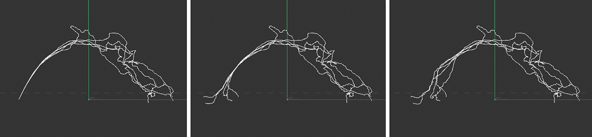 The image sequence shows increasing blend values from left to right.