

Object
The curve sections between the points of the spline geometry are subdivided in such a way that new points are created evenly, which all have this Step distance from each other. Smaller will values lead to correspondingly more subdivisions and points along the output spline. This mainly affects the radii of the sagging curves. With smaller Step values, sharper changes of direction near the suspension points are possible. The output geometry then acts like a thin rope or cable, for example. With larger Step values, changes in shape are softer and the curves output can look more like thicker cables or stiffer hoses, for example.
As the node automatically outputs a Bezier spline with tangents, rounded curves can still be output even with larger Step settings. However, short sections between the points of the input spline geometry may then be skipped, as also shown in the following image.
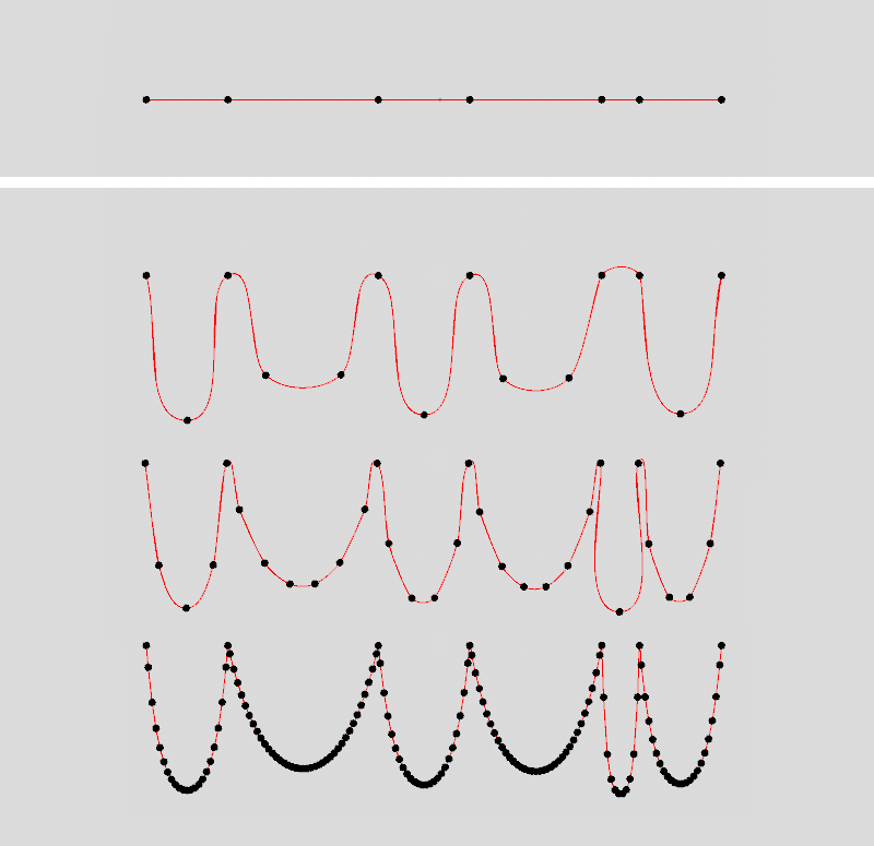 The initial spline can be seen at the top. The images below show the results of a gradual reduction in the step size. As can be seen at the right-hand end of the result spline, if the step sizes are too large, short sections between the starting points may be skipped and the curve may not sag in between.
Two modes are available here:
- Per Segment: Only sagging curves are calculated between the points, each of which delimits a segment at the original spline geometry.
- Per Point: Sagging ropes or cables are calculated between all points of the spline geometry.
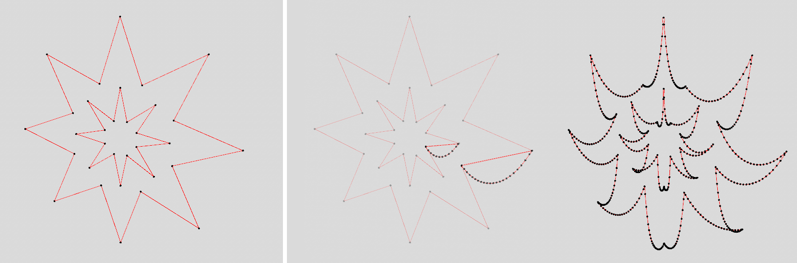 For this example, two star splines of different sizes were connected to form a spline geometry (shown on the far left). This gives us a spline that contains two segments (inner and outer star). In Per Segment mode, only the first and last points of each segment are connected with a sagging line (shown in the middle). In Per Point mode, on the other hand, all connections between the starting points are taken into account (shown on the far right).
Here you can define how the recalculation of the length of the sagging curve sections should take place:
- Automatic: The maximum length of each sagging curve depends on the distance between the original points of this spline section. If the points on the initiated spline are close to each other, the sagging cannot be as deep with the same Sag value as with points that are further apart.
- Fixed: In this mode, you use the Length value to specify an absolute maximum length for the sagging curve sections. If this length is shorter than the original distance between the points on the geometry introduced, no sagging can occur there.
In both cases, the actual length of the sagging sections can also be varied via Variation.
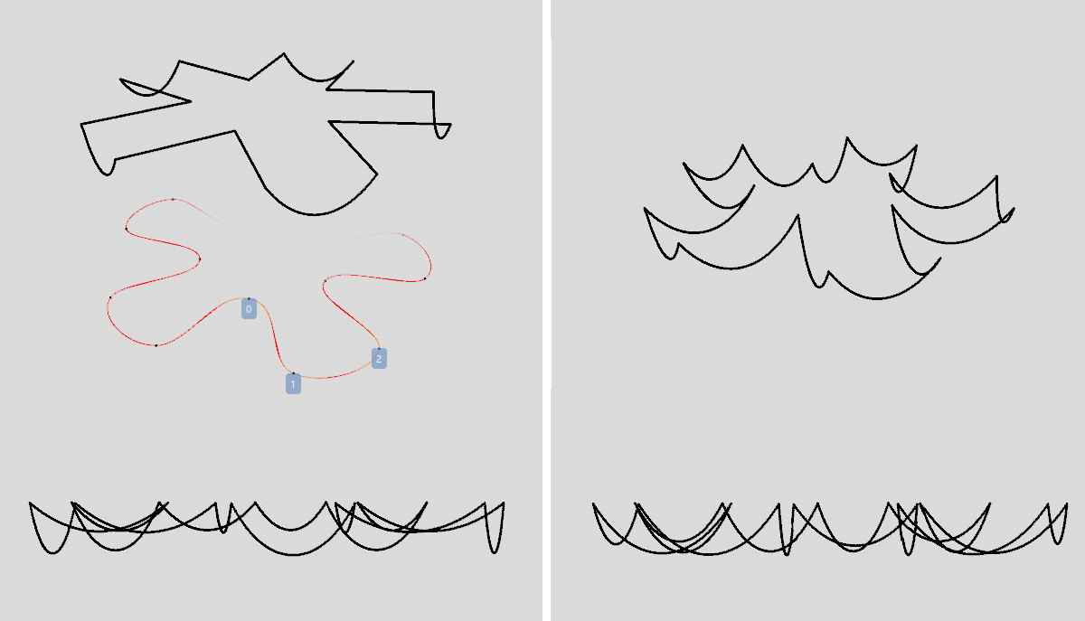
In the figure above, a Flower spline(indicated in red) was used on the left side as spline geometry with the Fixed mode. If a Length value is used that is shorter than the distance between two neighboring points, there is no sagging there (see section between points 0 and 1). If point distances are smaller than the Length value, the spline sags there accordingly (see section between points 1 and 2). This automatically results in different depths for the sagging at the result spline, as can be seen at the bottom left.
The right half of the figure above also uses a Flower spline, but this time in Automatic mode. Each section between two neighboring points will sag if a Sag value above 0% is used. The depth of the sag depends on the distance between the neighboring points.
This setting is only available if Sag Fixed is selected. Here you enter the maximum length for all sagging curve sections. The greater this value, the deeper the curves can sag. However, if this distance is shorter than the distance between two points on the spline introduced, there will be no sagging.
This setting is only available if Sag Automatic is selected and controls the maximum sagging of the curve sections between the points of the spline geometry introduced as a percentage. The depth of the sagging therefore also depends on the distance between the original pairs of points on the spline.
This allows you to randomly vary the length of each sagging curve section. This calculation is based on the separate Seed value. A new Seed value therefore leads to a recalculation of the variation.
This setting is only important if you are using a Variation above 0%. By increasing the Bias value, you reduce the intermediate stages for the variation of the sagging segments. With a Bias of 100%, this results in the spline sections either no longer sagging at all or as specified by the varied Length or Sag settings.
This setting defines the direction in which the sag will be calculated:
- Global: The spline sections always sag vertically downwards, i.e., they are deformed in the direction of the negative Y-axis.
- Local: The sag occurs in the direction of the negative Y-axis on the local modifier matrix.
- Spherical: The sag is calculated spherically, starting from the position of the local modifier matrix. The rotation angle, the size or the shear angle of this matrix are irrelevant.
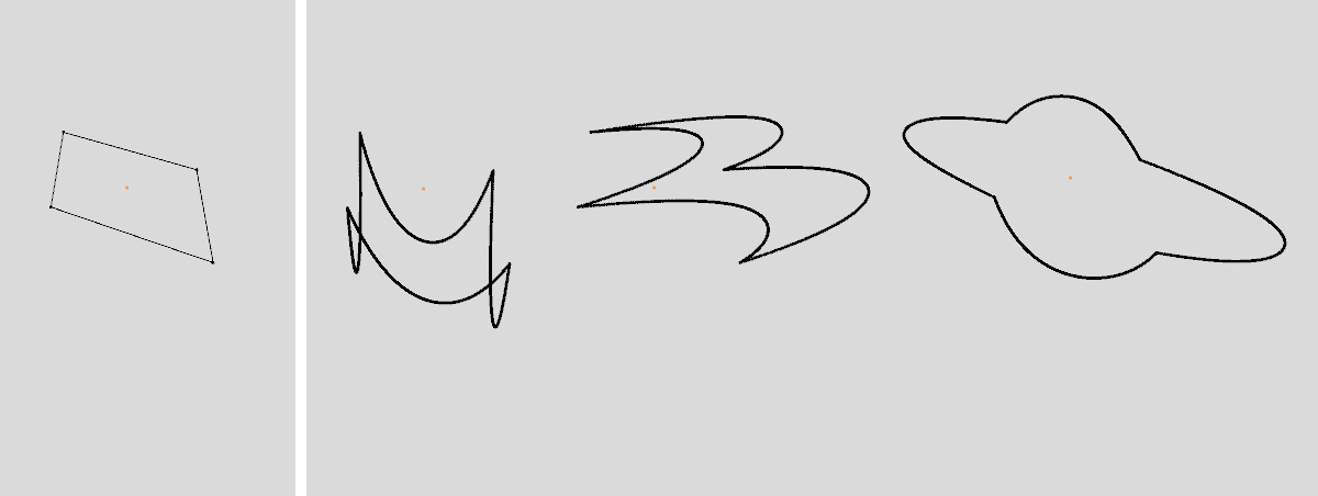 On the left is the initial spline, a rectangle. The figures on the right show examples of the Global, Local and Spherical modes in turn. Local and Spherical are each based on the Local modifier matrix.
This value is the basis for the random variation calculations of the node. A new Seed value therefore also leads to other variations in the sagging of the curve sections. However, a Variation value above 0% must be used for this.